Distributed land mobile radio architectures
Summary by NHIP
Distributed LMR voter system
The system provides communication in a distributed land mobile radio architecture using three voter comparators at separate sites. Each comparator receives radio frequency signals from a device, compares their signal strengths, and transmits the strongest signal to a central controller.
Claim Score by NHIP
Abstract
A system for providing communication in a distributed land mobile radio (LMR) system architecture. In some embodiments, the system includes a first controller associated with an LMR site. The first controller may be configured to control communication, via a communication channel, of a plurality of LMRs. In some embodiments, the system further includes a first repeater of a plurality of repeaters associated with the LMR site. The first repeater may include at least an active mode. The first repeater may be in the active mode to initiate a simulcast controller operation using the communication channel of the plurality of repeaters.
Term
7.5 yearsleft in the term
Expires 17 March 2034.
- Priority
- Filed
- Granted
- Today
- Expires
16 claims: 4 independent, 12 dependent
- 1A system for providing communication in a distributed land mobile radio (LMR) system architecture, the system comprising:a controller associated with at least one of a first LMR site, a second LMR site, or a third LMR site;a first voter comparator associated with the first LMR site, the first voter comparator configured to receive at least a first signal from a device;a second voter comparator associated with the second LMR site, the second voter comparator configured to receive at least a second signal from the device;and a third voter comparator associated with the third LMR site, the third voter comparator configured to receive at least a third signal from the device, wherein the first signal, the second signal, and the third signal are radio frequency signal signals, and wherein one voter comparator of the first voter comparator, the second voter comparator, and the third voter comparator (i) receives the first signal from the device or the first voter comparator, the second signal from the device or the second voter comparator, and the third signal from the device or the third voter comparator, (ii) compares signal strengths of the first signal, the second signal, and the third signal, and (iii) transmits one of the first signal, the second signal, or the third signal that has the greatest signal strength from the first signal, the second signal, and the third signal to the controller.
- 7A system for providing communication in a distributed land mobile radio (LMR) system architecture, the system comprising:a first controller associated with a first LMR site, the first controller configured to control communication between first devices within and remote to the first LMR site;a second controller associated with a second LMR site, the second controller configured to control communication between second devices within and remote to the second LMR site;and a third controller associated with at least one of the first LMR site or the second LMR site, wherein: upon failure of the first controller, the third controller is configured to control communication between the first devices within and remote to the first LMR site, and upon failure of the second controller, the third controller is configured to control communication between the second devices within and remote to the second LMR site;wherein controlling communication comprises controlling transmission of a plurality of signals.
- 12A system for providing communication in a distributed land mobile radio (LMR) system architecture, the system comprising:a first controller associated with a first LMR site, the first controller configured to control communication between first devices within and remote to the first LMR site, wherein controlling communication comprises controlling transmission of a plurality of signals;a second controller associated with a second LMR site, the second controller configured to control communication between second devices within and remote to the second LMR site;a transmitter associated with at least one of the first LMR site or the second LMR site and configured to transmit at least one signal of the plurality of signals to at least one of the first controller or the second controller;and a simulcast controller configured to receive a signal of the plurality of signals, assign a launch time to the signal, and transmit the signal to the transmitter, wherein the transmitter transmits the at least one signal of the plurality of signals to at least one of the first controller or the second controller at the launch time.
- 13Broadest claimClaim Score 54, average(NHIP)A system for providing communication in a distributed land mobile radio (LMR) system architecture, the system comprising:a first controller associated with a LMR site, the first controller configured to control communication, via a communication channel, of a plurality of LMRs;and a plurality of repeaters associated with the LMR site, the plurality of repeaters comprising: a first repeater comprising at least an active mode, wherein the first repeater is configured in the active mode to initiate a simulcast controller operation using the communication channel of the plurality of repeaters, and a second repeater;wherein the simulcast controller operation comprises: transmitting a radio call at least substantially simultaneously with the second repeater by the first repeater on the communication channel, and synchronizing, on the communication channel, a transmit time of calls transmitted by the first repeater and the second repeater.
Independent claims4
76 paragraphs in 5 sections, as filed
CROSS-REFERENCE TO RELATED APPLICATIONS
This application is a continuation of U.S. patent application Ser. No. 17/100,213, now U.S. Pat. No. 11,496,212, titled “Distributed Simulcast Architecture,” filed Nov. 20, 2020, which is a continuation of U.S. patent application Ser. No. 16/543,302, now U.S. Pat. No. 10,880,000, titled “Distributed Simulcast Architecture,” filed Aug. 16, 2019, which is a continuation of U.S. patent application Ser. No. 15/494,391, now U.S. Pat. No. 10,461,846, titled “Distributed Simulcast Architecture,” filed Apr. 21, 2017, which is a continuation of U.S. patent application Ser. No. 14/217,150, now U.S. Pat. No. 9,774,386, titled “Distributed Simulcast Architecture,” filed Mar. 17, 2014, which claims the benefit of and priority to U.S. Provisional Patent Application No. 61/790,588, titled “Distributed Simulcast Architecture” and filed Mar. 15, 2013, all of which are incorporated herein by reference in their entireties and for all purposes.
BACKGROUND
The statements in this section merely provide background information related to the present disclosure and may not constitute prior art.
Land Mobile Radio (LMR) systems are deployed by organizations requiring instant communication between geographically dispersed and mobile personnel. Current LMR systems can be configured to provide for radio communications between one or more sites and subscriber radio units in the field. A subscriber radio unit (hereinafter “radio”) may be a mobile unit or a portable unit. LMR systems can be as simple as two radio units communicating between themselves over preset channels, or they can be complex systems that include hundreds of radio units and multiple sites. Typical users of LMR systems include police departments, fire departments, medical personnel, security personnel, EMS, and the military.
Conventional and trunking LMR system architecture may include multiple LMR sites, each utilizing various equipment including, for example, dedicated site controllers, repeaters, voter comparator and simulcast controllers. Specifically, in simulcast system architecture, a prime site is deployed that hosts the site controllers, simulcast controllers and voter comparators. As the LMR system expands, additional equipment is needed, which becomes increasingly expensive to provide and maintain. Furthermore, each site in the LMR system is often controlled by equipment located at one of the sites comprising the LMR system or by the equipment located at the prime site. Accordingly, when such equipment fails, corresponding portions of the LMR system also fail. As such, conventional and trunking LMR system architecture lacks redundancy and, therefore, is often subject to single points of failure, thereby compromising the integrity of the LMR system architecture.
SUMMARY
In one embodiment, the present disclosure provides a system for providing communication in a distributed LMR system architecture, the distributed LMR system architecture comprising one or more subsystems in communication with a data network, the system comprising: one or more LMR sites comprising at least one of the one or more subsystems; one or more subsystem controllers disposed at each of the one or more LMR sites comprising the at least one subsystem, each subsystem controller having at least an active mode and a standby mode, wherein at least one subsystem controller is operable in the active mode to control communication between the one or more LMR sites in the at least one subsystem; and one or more repeaters disposed at each of the plurality of sites in the at least one subsystem, each of the repeaters operable to provide a communication channel, wherein each repeater has at least an active mode and a standby mode, and wherein at least one repeater is operable in the active mode to perform at least one of a simulcast controller operation and a voter comparator operation.
In another embodiment, the present disclosure provides a method for providing communication in a distributed land mobile radio (LMR) system architecture, the distributed LMR system architecture comprising one or more subsystems in communication with a data network, the method comprising: providing a subsystem controller in each of a plurality of LMR sites comprising one of the subsystems, each subsystem controller having at least an active mode and a standby mode; operating one of the subsystem controllers in the active mode to control communication between the plurality of LMR sites; operating the remaining subsystem controllers in the standby mode; providing a plurality of repeaters at each of the plurality of LMR sites comprising the subsystem, each repeater having at least an active mode and a standby mode; operating at least one of the repeaters in the active mode to perform at least one of a simulcast controller operation and a voter comparator operation; and operating the remaining repeaters in the standby mode.
Further embodiments and apparatuses, including other areas of applicability, will become apparent from the description provided herein. It should be understood that the description and specific examples are intended for purposes of illustration only and are not intended to limit the scope of the present disclosure in any manner.
BRIEF DESCRIPTION OF THE DRAWINGS
For a more complete understanding of various embodiments of the present invention and the advantages thereof, reference is now made to the following brief description, taken in connection with the accompanying drawings and detailed description, wherein like reference numerals represent like parts, and in which:
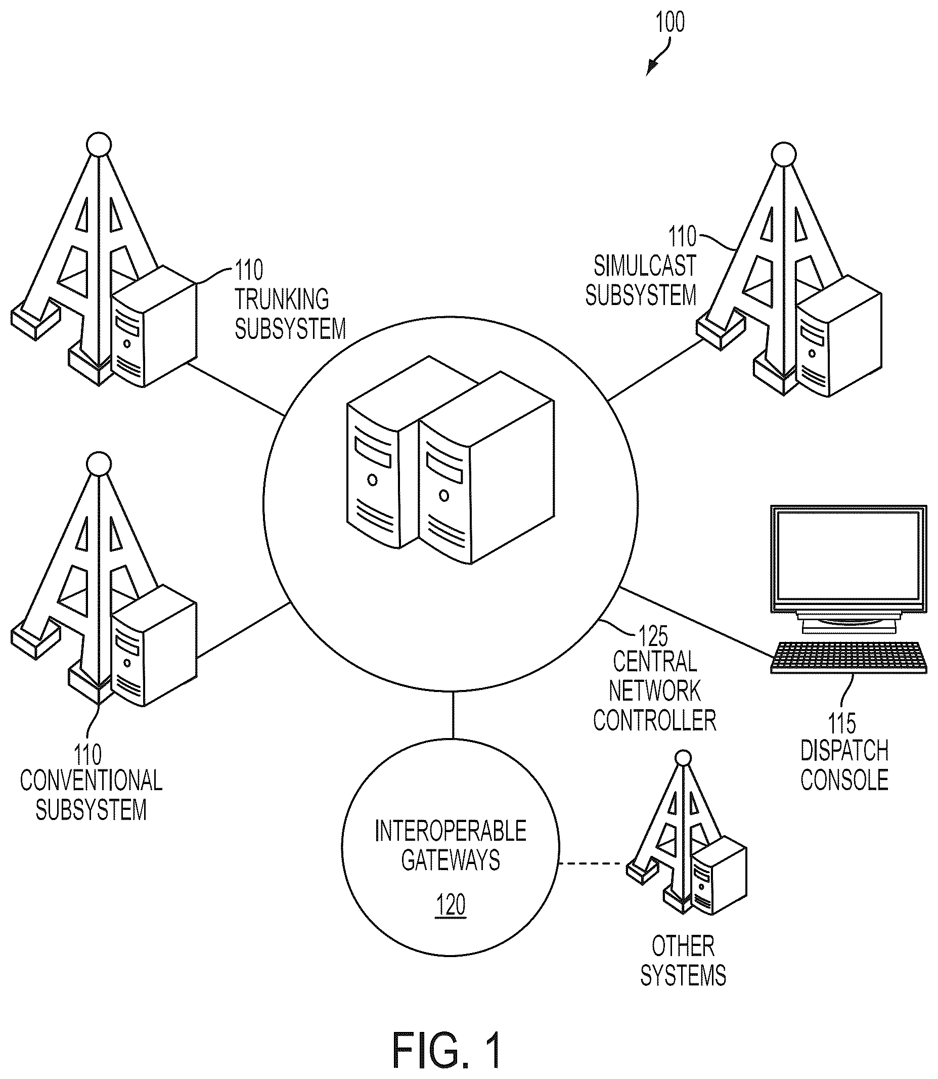
<figref idref="DRAWINGS">FIG. <b>1</b></figref> illustrates an example embodiment of a centralized LMR architecture;
<figref idref="DRAWINGS">FIG. <b>2</b></figref> illustrates an example embodiment of a conventional LMR system;
<figref idref="DRAWINGS">FIG. <b>3</b></figref> illustrates an example embodiment of a trunked LMR system;
<figref idref="DRAWINGS">FIG. <b>4</b></figref> illustrates an example embodiment of a hybrid LMR system;
<figref idref="DRAWINGS">FIG. <b>5</b></figref> illustrates an example embodiment of a simulcast LMR system;
<figref idref="DRAWINGS">FIG. <b>6</b></figref> illustrates an example embodiment of an LMR system incorporating a distributed architecture;
<figref idref="DRAWINGS">FIG. <b>7</b></figref> illustrates an example embodiment of the first trunked LMR subsystem provided in <figref idref="DRAWINGS">FIG. <b>6</b></figref>;
<figref idref="DRAWINGS">FIG. <b>8</b></figref> illustrates an example embodiment of the second trunked LMR subsystem provided in the distributed architecture of <figref idref="DRAWINGS">FIG. <b>6</b></figref>;
<figref idref="DRAWINGS">FIG. <b>9</b></figref> illustrates an example embodiment of one of the simulcast LMR subsystems provided in the distributed architecture of <figref idref="DRAWINGS">FIG. <b>6</b></figref>;
<figref idref="DRAWINGS">FIG. <b>10</b></figref> illustrates an example embodiment of system for providing receiver voting in a centralized architecture;
<figref idref="DRAWINGS">FIG. <b>11</b></figref> illustrates an example embodiment of a system for providing receiver voting in a distributed architecture;
<figref idref="DRAWINGS">FIG. <b>12</b></figref> illustrates an example embodiment of system for providing simulcast communication in a centralized architecture;
<figref idref="DRAWINGS">FIG. <b>13</b></figref> illustrates an example embodiment of a system for providing simulcast communication in a distributed architecture;
<figref idref="DRAWINGS">FIG. <b>14</b></figref> illustrates an example embodiment of a centralized simulcast subsystem;
<figref idref="DRAWINGS">FIG. <b>15</b></figref> illustrates an example embodiment of a trunked simulcast subsystem in a distributed architecture;
<figref idref="DRAWINGS">FIG. <b>16</b></figref> illustrates an example embodiment demonstrating simulcast controller and voter comparator redundancy in a distributed simulcast LMR architecture;
<figref idref="DRAWINGS">FIG. <b>17</b></figref> illustrates an example embodiment demonstrating network failure redundancy in a distributed simulcast LMR architecture; and
<figref idref="DRAWINGS">FIG. <b>18</b></figref> illustrates an example embodiment demonstrating site redundancy in a distributed simulcast LMR architecture.
DETAILED DESCRIPTION OF THE DRAWINGS
In the following detailed description and accompanying drawings, numerous specific details are set forth to provide a thorough understanding of the present disclosure. However, those skilled in the art will appreciate that the present disclosure may be practiced, in some instances, without such specific details. In other instances, well-known elements have been illustrated in schematic or block diagram form in order not to obscure the present disclosure in unnecessary detail. Additionally, for the most part, specific details, and the like, have been omitted inasmuch as such details are not considered necessary to obtain a complete understanding of the present disclosure, and are considered to be within the purview of persons of ordinary skill in the relevant art.
It is further noted that, unless indicated otherwise, all functions described herein may be performed in hardware or as software instructions for enabling a computer, radio, or other device to perform predetermined operations, where the software instructions are embodied on a computer readable storage medium, such as RAM, a hard drive, flash memory, or other type of computer readable storage medium known to a person of ordinary skill in the art. In certain embodiments, the predetermined operations of the computer, radio, or other device are performed by a processor such as a computer or an electronic data processor in accordance with code such as computer program code, software, firmware, and, in some embodiments, integrated circuitry that is coded to perform such functions. Furthermore, it should be understood that various operations described herein as being performed by a user may be operations manually performed by the user, or may be automated processes performed either with or without instruction provided by the user.
An LMR system may employ a centralized architecture whereby various LMR subsystems are connected by a central network controller and associated network equipment. <figref idref="DRAWINGS">FIG. <b>1</b></figref> illustrates an example of a centralized LMR architecture <b>100</b>, which includes various LMR subsystems <b>110</b>, dispatch stations <b>115</b>, and gateway equipment <b>120</b> connected by a central network controller <b>125</b>. The central network controller <b>125</b> includes equipment for operating and controlling each of the various LMR subsystems <b>110</b>, dispatch stations <b>115</b>, and gateway equipment <b>120</b>. The various LMR subsystems <b>110</b> may include any of a conventional LMR system, trunking LMR system, hybrid LMR system, or wide area systems such as a simulcast LMR system or multicast LMR system. Examples of such LMR systems are briefly discussed below with reference to <figref idref="DRAWINGS">FIGS. <b>2</b>-<b>5</b></figref>.
<figref idref="DRAWINGS">FIG. <b>2</b></figref> illustrates an example of a conventional LMR system <b>200</b>. Conventional systems are typically deployed in regions covering large geographic areas and/or comprising a moderate quantity of users. In a conventional system, a dedicated repeater channel is provided for system user groups, and the user chooses the channel or channels on which he wishes to communicate. Often, system user groups are organized based on responsibility, such as Fire, Police, EMS, Public Works, and Mutual Aid. In most cases, each of these groups has a corresponding dedicated repeater channel <b>202</b>, which provides a frequency for communicating a call.
<figref idref="DRAWINGS">FIG. <b>3</b></figref> illustrates an example of a trunked LMR system <b>300</b>. Trunked systems are typically deployed in regions covering moderate geographical areas and/or comprising a large quantity of users. Trunked systems have a shared pool of repeater channels for use among system user groups. The repeater channels at each site are divided into a control channel <b>302</b> and multiple voice channels <b>304</b>. The control channel <b>302</b> registers a radio into the system and dynamically coordinates radio talkgroup Push-to-Talk (PTT) with an available voice channel.
In a trunked radio system, system talkgroups are often organized based on responsibility, such as Fire, Police, EMS, Public Works, and Mutual Aid. The user selects the talkgroup with which he wishes to communicate, and the trunked system then allocates the radio channel used for the voice transmission. For LMR systems having multiple groups with access to multiple channels at each site, a trunked system may be implemented to increase the system's efficiency.
A hybrid system combines conventional and trunked repeater channels into a single system. In hybrid systems, users can be organized functionally for either the conventional or trunked part of the system, as needed. <figref idref="DRAWINGS">FIG. <b>4</b></figref> illustrates an example embodiment of a hybrid LMR system <b>400</b>, which includes a conventional site <b>410</b> and a trunked site <b>420</b>.
In addition to the foregoing, LMR system types may include wide area systems, which, in some embodiments, are designed to enable radios to move throughout an area without their users needing to change channels while roaming. A simulcast system is an example of a wide area system. An example of a simulcast system <b>500</b> is illustrated in <figref idref="DRAWINGS">FIG. <b>5</b></figref>. The simulcast system <b>500</b> includes a single master site <b>510</b> (also referred to herein as a prime site) and multiple radio sites <b>520</b>. The master site <b>510</b> synchronizes the system timing so that calls are transmitted simultaneously to all sites for a given repeater channel. Thus, a call is transmitted simultaneously to all sites at the same frequency. This synchronization reduces the quantity of frequencies needed for the system and simplifies frequency coordination.
Another example of a wide area LMR system is a multicast system. In multicast systems, different transmitters within adjacent geographic areas communicate on different radio channel frequencies. The multicast system switches the user to the proper channel automatically. The multicast system configuration offers similar coverage advantages of a simulcast system at a reduced cost. However, multicast systems require multiple frequencies, and their users need to change mobile channels as they move between sites.
Referring again to <figref idref="DRAWINGS">FIG. <b>1</b></figref>, the central network controller <b>125</b> includes equipment for operating and controlling each of the various LMR subsystems <b>110</b>, dispatch stations <b>115</b>, and gateway equipment <b>120</b>. As the LMR system <b>100</b> expands, additional capacity is needed in the network controller often requiring additional network controller equipment, which becomes increasingly expensive to provide and maintain. Furthermore, sites in the subsystems <b>110</b> may be controlled by equipment located at the central network controller <b>125</b>. When such equipment fails, the LMR system <b>100</b> fails. As such, centralized LMR architecture lacks redundancy and, therefore, is often subject to single points of failure, thereby compromising the integrity of the LMR system architecture.
The present disclosure provides a system and method for providing communication in a distributed LMR system architecture. The distributed architecture eliminates the need for a central network controller and associated network equipment. Instead, the functionality of the network controller is distributed among controllers at each of the subsystems comprising the LMR system, thereby providing peer-to-peer communication over an internet protocol (IP) network.
<figref idref="DRAWINGS">FIG. <b>6</b></figref> illustrates an example of an LMR system <b>600</b> incorporating a distributed architecture in accordance with the present disclosure. The distributed LMR architecture <b>600</b> provided in <figref idref="DRAWINGS">FIG. <b>6</b></figref> is comprised of various LMR subsystems <b>610</b>-<b>630</b> and dispatch stations <b>650</b> connected via IP connections <b>600</b> comprising an IP network. In the embodiment illustrated in <figref idref="DRAWINGS">FIG. <b>6</b></figref>, the distributed LMR architecture <b>600</b> incorporates first and second trunked subsystems <b>610</b> and <b>620</b> and simulcast subsystems <b>630</b>, however, it should be appreciated that other LMR subsystems may be included, such as, for example, conventional, hybrid, multicast, or any other LMR systems discussed herein.
As mentioned above, the distributed LMR architecture <b>600</b> eliminates the central network controller and associated equipment that is typically provided with a centralized architecture, and instead distributes the functionality of the central network controller and associated equipment among subsystem controllers deployed at each of the subsystems <b>610</b>-<b>630</b> comprising the distributed LMR architecture <b>600</b>. In some embodiments, the central network controller functionality and associated equipment may also be distributed among dispatch stations <b>650</b>.
As discussed in greater detail below, the distributed LMR architecture disclosed herein incorporates repeaters, subsystem controllers, network management systems, and dispatch consoles. In some embodiments, these components are IP-based and may be managed remotely over the IP network.
Repeaters provide channels/frequencies for over-the-air communication and, in some embodiments, are equipped with circuitry to provide integrated voter comparator and simulcast controller functionality/operations.
Subsystem controllers provide interface and gateway functionality for interconnecting multiple types of LMR subsystems through a common IP network. The subsystem controllers enable dispatch console control of local repeaters, provide distributed call control and mobility management functions, and enable direct routing of calls between conventional and trunked systems and/or dispatch consoles without talkgroup patching. The distributed architecture of the disclosed system enables each subsystem controller to perform central network controller functionality for a call originating from its local subsystem, thereby eliminating the need for a dedicated central network controller. As discussed in greater detail below, providing a subsystem controller at each site in a subsystem provides multi-level redundancy of the controller functionality, and allows for communication in case of equipment or site failure.
Network management systems provide redundant, web-based, and centralized network management functionality for the infrastructure comprising the distributed architecture system, including the various LMR subsystems (e.g., conventional, trunked, etc.), subsystem controllers, and dispatch consoles. The network management systems provide management and deployment of subscriber and talkgroup records; radio administration including radio inhibit, dynamic regrouping, and radio check; agency specific management of subscriber records, talkgroup records, and reporting; and pre-defined and custom roles that restrict operator access and activity based on access credentials. The network management systems also provide real-time fault monitoring of system components, extensive reports covering system usage and user activities, real-time monitoring of user and channel activities, and full redundancy capability.
Dispatch consoles provide interoperability via direct IP connection to the LMR subsystems. In some embodiments, the dispatch consoles are IP-based and fully distributed with no requirement for central control equipment, thereby allowing extensive scalability and expansion with no single point of failure.
Reference is now made to <figref idref="DRAWINGS">FIG. <b>7</b></figref>, which illustrates an example embodiment of the first trunked LMR subsystem <b>610</b> of <figref idref="DRAWINGS">FIG. <b>6</b></figref>. In the example embodiment illustrated in <figref idref="DRAWINGS">FIG. <b>7</b></figref>, the first trunked subsystem <b>610</b> comprises a single site trunked subsystem, however, it should be appreciated that the trunked subsystem could include multiple sites. The trunked subsystem <b>610</b> includes a plurality of repeaters <b>710</b> and two subsystem controllers <b>720</b>. Each of the repeaters <b>710</b> represents a channel (a combination of transmit and receive operations), wherein one of the repeaters (e.g., <b>710</b>A) operates a control channel <b>730</b>, while the remaining repeaters <b>710</b> are designated for voice operation.
The trunked subsystem <b>610</b> provides redundancy by incorporating two subsystem controllers <b>720</b>. One of the subsystem controllers <b>720</b> is active, and the other is on standby. If the active subsystem controller <b>720</b> fails, then the standby subsystem controller <b>720</b> becomes active to provide a fail-safe transition with no visible impact to the radio users <b>725</b> and <b>740</b>. As discussed above, the local subsystem controller <b>720</b> performs call controls, thereby eliminating the need for a central controller.
In accordance with the embodiment illustrated in <figref idref="DRAWINGS">FIG. <b>7</b></figref>, the single site trunked subsystem <b>610</b> operates in accordance with the following example for hosting a call. A radio user <b>725</b> initiates a call through the control channel <b>730</b>. The active subsystem controller <b>720</b> processes the user-initiated call and assigns a voice channel <b>735</b> for voice communication. The radio users <b>725</b> and <b>740</b> communicate with each other over the assigned voice channel <b>735</b>.
Reference is now made to <figref idref="DRAWINGS">FIG. <b>8</b></figref>, which illustrates an example embodiment of the second trunked LMR subsystem <b>620</b> of <figref idref="DRAWINGS">FIG. <b>6</b></figref>. In the example embodiment illustrated in <figref idref="DRAWINGS">FIG. <b>8</b></figref>, the second trunked subsystem <b>620</b> comprises a wide area multicast trunked subsystem. The multicast trunked subsystem <b>620</b> comprises a plurality of sites <b>800</b>A-<b>800</b>C connected with each other to form a wide area trunked system. Each of the sites <b>800</b>A-<b>800</b>C is similar to the single trunked site discussed above with respect to <figref idref="DRAWINGS">FIG. <b>7</b></figref> and, therefore, includes a plurality of repeaters <b>810</b> and two subsystem controllers <b>820</b>. In some embodiments, adjacent sites in the multicast trunked subsystem <b>620</b> operate at a different frequency to ensure there is no radiofrequency (RF) interference between the sites. However, in some embodiments, frequencies may be reused in non-overlapping sites.
The sites <b>800</b>A-<b>800</b>C are connected via their respective subsystem controllers <b>820</b>, thereby eliminating the need for a central controller. The subsystem controllers <b>820</b> communicate directly with each other to setup a wide area call between interested sites. For example, a call originating from a first site (e.g., site <b>800</b>A) is transferred to other interested sites (e.g., sites <b>800</b>B and <b>800</b>C) using the local subsystem controllers <b>820</b>.
In accordance with the embodiment illustrated in <figref idref="DRAWINGS">FIG. <b>8</b></figref>, the multicast trunked subsystem <b>620</b> operates in accordance with the following example for hosting a call. A radio user <b>805</b> from site <b>800</b>A originates a call. The active subsystem controller <b>820</b> in site <b>800</b>A determines the other sites interested in the call and sends them a call notification <b>815</b>. The active subsystem controller <b>820</b> located in each site <b>800</b>A-<b>800</b>C assigns a voice channel <b>825</b> to the call. The active subsystem controller <b>820</b> in site <b>800</b>A transfers the call <b>835</b> to the other subsystem controllers <b>820</b>, and the radios use the assigned voice channel <b>825</b> to transmit or receive within their respective site.
Reference is now made to <figref idref="DRAWINGS">FIG. <b>9</b></figref>, which illustrates an example embodiment of one of the simulcast LMR subsystems <b>630</b> of <figref idref="DRAWINGS">FIG. <b>6</b></figref>. In the example embodiment illustrated in <figref idref="DRAWINGS">FIG. <b>9</b></figref>, the simulcast subsystem <b>630</b> is a trunked simulcast subsystem, which employs one simulcast control channel <b>915</b> and one or more simulcast voice channels <b>925</b> to provide trunking communication between radio users <b>905</b> within the subsystem <b>630</b>. Each site <b>900</b> in the simulcast subsystem <b>630</b> includes a plurality of repeaters <b>910</b> (one to provide active or standby control channel functionality, or operations, and additional repeaters <b>910</b> for each voice channel provided in the subsystem <b>630</b>), and at least one subsystem controller <b>920</b>.
To provide redundancy, a single subsystem controller <b>920</b> located at one of the sites <b>900</b> is active for the entire subsystem <b>630</b>, and the remaining subsystem controllers <b>920</b> located at the remaining sites <b>900</b> serve as standby. Additionally, a single repeater <b>910</b> located at one of the sites <b>900</b> is active to provide control channel functionality, or operations, and a single repeater <b>910</b> located at each of the remaining sites <b>900</b> is provided as standby in the event of failure of the active control channel repeater <b>910</b>. The remaining repeaters <b>910</b> located at each of the sites are generally designated as voice channels for each of the channels provided by the subsystem <b>630</b>, however, each repeater is also capable of performing voting and simulcast operations as explained below.
The trunked simulcast subsystem <b>630</b> employs both voting and simulcast operations to provide communication across the subsystem <b>630</b>. In a simulcast operation, a single channel is usually provided by a collection of repeaters <b>910</b> distributed across multiple geographic sites comprising the subsystem (e.g., sites <b>900</b>A, <b>900</b>B, and <b>900</b>C), wherein the repeaters <b>910</b> operate on the same frequency pair (transmit and receive), under voted and simulcast configurations, to expand the coverage area of the subsystem <b>630</b> into the sites (e.g., sites <b>900</b>A, <b>900</b>B, and <b>900</b>C). In other words, in some embodiments, a single channel may be provided by one repeater <b>910</b> at each of the sites <b>900</b>A-<b>900</b>C in the subsystem <b>630</b>.
In a traditional simulcast LMR system, the capability of a radio's communication to reach the prime site can be limited by the transmit power of the radio. One way to improve the talkback capability of the radios is to use receiver voting to determine the location (e.g., site) of the radio to determine the best means for communicating with the radio. <figref idref="DRAWINGS">FIG. <b>10</b></figref> provides an example illustration of a traditional architecture for providing receiver voting. Traditionally, receiver voting is performed by placing a number of additional radio receivers (towers) <b>1010</b> in strategic locations within the simulcast system <b>1015</b> to receive the RF signal <b>1020</b> from a transmitting radio <b>1025</b>. Each tower <b>1010</b> then sends the received signal and signal strength data <b>1035</b> to a voter comparator <b>1030</b>. The voter comparator <b>1030</b> compares the signal strength of each received signal and selects the best signal <b>1040</b> to use for communication. The voter comparator <b>1030</b> then sends the best signal <b>1040</b> to the subsystem controller at the prime site for further processing. By increasing the number of radio receivers within a subsystem, the overall system talkback coverage area may be expanded.
In traditional systems, such as that illustrated in <figref idref="DRAWINGS">FIG. <b>10</b></figref>, there is one voter comparator per channel, and the voter comparator is located at a prime site or at the central network controller in a centralized LMR architecture, which may not be the same site at which the transmitting radio is located. In these traditional implementations, voter comparators present a single point of failure for a channel.
In accordance with an embodiment of the present disclosure, the single voter comparator is eliminated (as is the central network controller), and the voter comparator functionality is integrated into each repeater in the subsystem. For example, <figref idref="DRAWINGS">FIG. <b>11</b></figref> illustrates an example of such an embodiment wherein repeaters <b>1110</b> located at different sites <b>1115</b> (similar to the repeaters <b>910</b> located at the sites <b>900</b> in <figref idref="DRAWINGS">FIG. <b>9</b></figref>) throughout the subsystem <b>1130</b> have integrated voter comparator functionality. Although each of the repeaters <b>1110</b> in the subsystem <b>1130</b> have voter comparator functionality, the voter comparator functionality of only one of the repeaters <b>1110</b> (for a particular channel) is configured to be active at any given time. In some embodiments, the repeaters and subsystem controllers communicate with each other to determine which repeater is active. Additionally, in some embodiments, the network management system may configure a particular repeater to be active.
The repeater <b>1110</b> with active voter comparator functionality may perform voter comparator operations, including voting of signals <b>1120</b> for all sites in the subsystem <b>1130</b> (for the particular channel assigned to the repeater <b>1110</b>). The voter comparator functionality of the remaining repeaters <b>1110</b> for the channel are on standby in case of failure of the active repeater <b>1110</b>. This redundancy reduces the potential of operational downtime because, if the voter comparator functionality of one repeater <b>1110</b> fails, the voter comparator functionality of another repeater <b>1110</b> will become active.
If an adequate number of frequencies are not available for communication in an LMR system, a simulcast operation may be performed to reuse frequencies and cover a large geographic area. Referring again to <figref idref="DRAWINGS">FIG. <b>9</b></figref>, a simulcast channel may utilize several geographically separated repeaters <b>910</b> which transmit simultaneously on the same frequency, thereby reducing the number of frequencies needed for the entire subsystem <b>630</b>. For example, repeaters <b>910</b>A, <b>910</b>B, and <b>910</b>C located at sites <b>900</b>A, <b>900</b>B, and <b>900</b>C, respectively, may all transmit simultaneously on the same frequency to provide simulcast communication between radios in the subsystem <b>630</b>.
In a traditional simulcast LMR system, such as that illustrated in <figref idref="DRAWINGS">FIG. <b>12</b></figref>, a simulcast channel uses a simulcast controller <b>1210</b>, which synchronizes the launch time (transmit time) of calls transmitted to sites <b>1220</b> in the system <b>1225</b>. The simulcast controller <b>1210</b> receives the audio signal <b>1215</b>, assigns a launch time, and then sends the signal <b>1215</b> to each transmitter/repeater <b>1230</b>. Each transmitter <b>1230</b> transmits the signal at its respective site <b>1220</b> pursuant to the launch time, and radios <b>1235</b> communicating on that channel receive the signal from the multiple transmitters <b>1230</b>. The timing system implemented by the simulcast controllers <b>1210</b> and transmitters <b>1230</b> synchronizes the launch time in the transmitter <b>1230</b> so that calls are transmitted simultaneously from all sites <b>1220</b> for a given repeater channel. This synchronization ensures that the transmission on the same frequency is in phase, thereby reducing interference.
In traditional simulcast LMR systems, such as that illustrated in <figref idref="DRAWINGS">FIG. <b>12</b></figref>, a single simulcast controller <b>1210</b> is provided for each channel. The simulcast controller <b>1210</b> is typically located at a prime site or at the central network controller in a centralized LMR architecture. Accordingly, the single simulcast controller <b>1210</b> in a traditional simulcast LMR system provides a single point of failure for a channel.
In accordance with an embodiment of the present disclosure, the single simulcast controller is eliminated (as is the central network controller), and the simulcast controller functionality is integrated into each repeater in the subsystem. For example, <figref idref="DRAWINGS">FIG. <b>13</b></figref> illustrates an example of such an embodiment wherein repeaters <b>1310</b> located at different sites <b>1315</b> (similar to the repeaters <b>910</b> located at the sites <b>900</b> in <figref idref="DRAWINGS">FIG. <b>9</b></figref>) throughout the subsystem <b>1330</b> have integrated simulcast controller functionality. Although each of the repeaters <b>1310</b> in the subsystem <b>1330</b> have simulcast controller functionality, the simulcast controller functionality of only one of the repeaters <b>1310</b> is configured to be active at any given time. In some embodiments, the repeaters and subsystem controllers communicate with each other to determine which repeater is active. Additionally, in some embodiments, the network management system may configure a particular repeater to be active.
Referring again to <figref idref="DRAWINGS">FIG. <b>9</b></figref>, the repeater <b>910</b> with active simulcast controller functionality may perform simulcast controller operations across all sites <b>900</b> in the subsystem <b>630</b>. In some embodiments, one repeater <b>910</b> may provide simulcast controller functionality for a particular channel while other repeaters <b>910</b> allocated to that channel are on standby to provide redundancy. In other words, one repeater <b>910</b> for each channel may have active simulcast controller functionality, and the simulcast controller functionality of the remaining repeaters <b>910</b> in the subsystem <b>630</b> are on standby in case of failure of the active repeater <b>910</b> for the standby repeater's respective channel. This redundancy reduces the potential of operational downtime because, if the simulcast controller functionality of one repeater <b>910</b> fails, the simulcast controller functionality of another repeater <b>910</b> will become active.
For example, in one embodiment, repeaters <b>910</b>A, <b>910</b>B, and <b>910</b>C are allocated to a particular channel. Repeater <b>910</b>A may be active to provide simulcast controller operations for the channel allocated to repeaters <b>910</b>A, <b>910</b>B, and <b>910</b>C, and repeaters <b>910</b>B and <b>910</b>C are on standby. If repeater <b>910</b>A fails, repeater <b>910</b>B or repeater <b>910</b>C may become active to provide simulcast controller functionality for the channel allocated to repeaters <b>910</b>A, <b>910</b>B, and <b>910</b>C.
It should be appreciated that other variations and embodiments may be considered within the scope of the present disclosure. For example, in some embodiments, one repeater <b>910</b> may provide active simulcast controller functionality for more than one channel in the subsystem <b>630</b>. In this embodiment, the active simulcast repeater <b>910</b> may provide simulcast controller functionality for some, or all, of the channels in the subsystem <b>630</b>. For example, repeater <b>910</b>A may be allocated to a first channel, repeater <b>910</b>B allocated to a second channel, and repeater <b>910</b>C allocated to a third channel. Repeater <b>910</b>A may provide active simulcast controller functionality for the first channel, second channel, third channel, or any combination thereof, and the remaining repeaters <b>910</b>B and <b>910</b>C may operate in standby mode.
In accordance with an embodiment of the present disclosure, the trunked simulcast subsystem <b>630</b> may operate in accordance with the following example call sequence discussed with reference to <figref idref="DRAWINGS">FIG. <b>9</b></figref>. A radio <b>905</b>A initiates a call through the control channel <b>915</b>. The active subsystem controller <b>920</b> (e.g., subsystem controller <b>920</b> in site <b>900</b>A) processes the user-initiated call and assigns a voice channel <b>925</b> for the call. The radio users <b>905</b> communicate with each other over the voice channel <b>925</b>. Any request from the initiating user <b>905</b>A is received by one or more repeaters <b>910</b> of the channel, and the repeater <b>910</b> with active voter comparator functionality (e.g., repeater <b>910</b>A) then performs the voter comparator operation to select the best signal. Additionally, any data packet sent to the initiating user <b>905</b>A or other radio users <b>905</b> is sent to all repeaters <b>910</b> of the channel <b>925</b> through the repeater <b>910</b> with active simulcast controller functionality (e.g., repeater <b>910</b>A). The repeaters <b>910</b> then simultaneously transmit the data to the radios <b>905</b> over the channel <b>925</b>. In the embodiment discussed herein, both the voter comparator and simulcast controller functionality is provided by a single repeater (<b>910</b>A). However, it should be appreciated that, in some embodiments, the voter comparator functionality and simulcast controller functionality may be provided by separate repeaters.
As discussed above and illustrated in <figref idref="DRAWINGS">FIG. <b>14</b></figref>, traditional simulcast LMR systems <b>1400</b> include a prime site <b>1410</b>, which hosts voter comparators, simulcast controllers, and a simulcast subsystem controller, thereby providing simulcast synchronization and voter comparator functionality for all channels in the system <b>1400</b>. The traditional simulcast LMR system <b>1400</b> embodies a centralized architecture, wherein the prime site <b>1410</b> acts as a central network controller for all sites <b>1420</b> in the system <b>1400</b>. Thus, each site <b>1420</b> relies on the constant availability of the prime site <b>1410</b>, and is therefore susceptible to loss of the simulcast and voter comparator functionality in the event of prime site failure.
Referring now to <figref idref="DRAWINGS">FIG. <b>15</b></figref>, and in accordance with the forgoing discussion of the present disclosure, the trunked simulcast subsystem <b>1500</b> of the distributed LMR architecture eliminates the need for a dedicated prime site or prime site controller. The availability of simulcast controller functionality and voter comparator functionality in each repeater enables the distribution of the prime site functionality of each channel to different sites <b>1510</b> in the subsystem <b>1500</b>. Accordingly, any repeater may provide prime site functionality/operations for a channel, wherein providing prime site functionality/operations for a channel includes providing simulcast controller functionality (i.e., performing simulcast controller operations) and/or providing voter comparator functionality (i.e., providing voter comparator operations) for the channel. Prime site functionality of each repeater may be assigned through configuration, or dynamically. For example, as shown in <figref idref="DRAWINGS">FIG. <b>15</b></figref>, a first site <b>1510</b>A may provide prime site functionality for a first channel, a second site <b>1510</b>B may provide prime site functionality for a second channel, a third site <b>1510</b>C may provide prime site functionality for a third channel, and a fourth site <b>1510</b>D may provide prime site functionality for a fourth channel. Other repeaters in the subsystem <b>1500</b> are configured as standbys and become active upon failure of the primary repeater (i.e., the repeater providing active voter comparator/simulcast controller functionality).
As illustrated in <figref idref="DRAWINGS">FIGS. <b>9</b> and <b>15</b></figref>, the distributed simulcast architecture also eliminates the need for a central controller to process calls. Instead, the trunked simulcast subsystem controller (<b>920</b>) performs control for all calls. If the primary subsystem controller fails, one of the standby subsystem controllers becomes active, thereby providing redundancy and improved reliability in comparison to a centralized architecture.
Referring briefly to <figref idref="DRAWINGS">FIG. <b>6</b></figref>, the dispatch centers <b>650</b> include dispatch consoles connected to other components/subsystems in the distributed LMR architecture system <b>600</b>. Each console is peer to other consoles in the system <b>600</b> and is fully distributed, thereby ensuring that the impact of a console failure is localized to the corresponding dispatch center <b>650</b>, and does not affect the remaining components/subsystems in the system <b>600</b>.
Reference is now made to <figref idref="DRAWINGS">FIGS. <b>16</b>-<b>18</b></figref>, which are provided in support of the following description of various redundancy advantages provided by the disclosed distributed simulcast LMR architecture. Specifically, the disclosed distributed simulcast architecture provides redundancy in at least three aspects: (i) simulcast controller and voter comparator redundancy, (ii) network failure redundancy, and (iii) site redundancy.
<figref idref="DRAWINGS">FIG. <b>16</b></figref> illustrates an example embodiment demonstrating simulcast controller and voter comparator redundancy in the disclosed distributed simulcast LMR architecture. As illustrated in the example embodiment in <figref idref="DRAWINGS">FIG. <b>16</b></figref>, simulcast controller functionality and voter comparator functionality is shown distributed between multiple simulcast sites <b>1615</b> in a distributed simulcast subsystem <b>1610</b>. In the subsystem <b>1610</b>A, sites <b>1615</b>A, <b>1615</b>B, <b>1615</b>C, and <b>1615</b>D provide prime site functionality for channels one, two, three, and four, respectively, and site <b>1615</b>D also provides the active subsystem controller. In subsystem <b>1610</b>B, the repeater providing the simulcast controller/voter comparator functionality at site <b>1615</b>A fails, and the prime site functionality for channel one changes to one of the standby repeaters located at one of the other sites. In this example, site <b>1615</b>C assumes prime site functionality for channel one. As shown in the subsystem <b>1610</b>B, site <b>1615</b>C provides prime site functionality for channels one and three. In the embodiment illustrated in <figref idref="DRAWINGS">FIG. <b>16</b></figref>, the subsystem controller location at site <b>1615</b>D remains unchanged.
<figref idref="DRAWINGS">FIG. <b>17</b></figref> illustrates an example embodiment demonstrating network failure redundancy in the disclosed distributed simulcast LMR architecture. In <figref idref="DRAWINGS">FIG. <b>17</b></figref>, a trunked simulcast subsystem <b>1700</b> includes sites <b>1715</b>A, <b>1715</b>B, <b>1715</b>C, and <b>1715</b>D providing prime site functionality for channels one, two, three, and four, respectively, and site <b>1715</b>D also providing the active subsystem controller for the subsystem <b>1700</b>. As illustrated in <figref idref="DRAWINGS">FIG. <b>17</b></figref>, if a network failure breaks the trunked simulcast subsystem <b>1700</b> into halves <b>1710</b> and <b>1720</b>, each half becomes a smaller simulcast subsystem.
One of the subsystem controllers in each of the smaller subsystems <b>1710</b> and <b>1720</b> becomes active and continues to provide user communication on a reduced number of channels. For example, in the first reduced subsystem <b>1710</b>, the subsystem controller at site <b>1715</b>A becomes active and provides call control functionality for sites <b>1715</b>A and <b>1715</b>C. In the second reduced subsystem <b>1720</b>, the subsystem controller at site <b>1715</b>D remains active and provides call control functionality for sites <b>1715</b>B and <b>1715</b>D. This built-in redundancy ensures that users in each half <b>1710</b> and <b>1720</b> can still communicate with each other without interfering with RF signals in the overlapping area.
<figref idref="DRAWINGS">FIG. <b>18</b></figref> illustrates an example embodiment demonstrating site redundancy in the disclosed distributed simulcast LMR architecture. In <figref idref="DRAWINGS">FIG. <b>18</b></figref>, a trunked simulcast subsystem <b>1800</b> includes sites <b>1815</b>A, <b>1815</b>B, <b>1815</b>C, and <b>1815</b>D providing prime site functionality for channels one, two, three, and four, respectively, and site <b>1815</b>A also providing the active subsystem controller for the subsystem <b>1800</b>. Site redundancy is enabled by the combination of redundant simulcast controller functionality and voter comparator functionality in each repeater and a redundant subsystem controller at each site <b>1815</b>. Therefore, in case of a catastrophic failure of a site <b>1815</b>, the rest of the sites <b>1815</b> continue to provide coverage with little impact on the subsystem <b>1800</b>. For example, as shown in <figref idref="DRAWINGS">FIG. <b>18</b></figref>, if site <b>1815</b>A experiences a catastrophic failure, one of the standby repeaters located at one of the other sites (in this example, site <b>1815</b>C) is activated and assumes prime site functionality for channel one. Additionally, one of the standby subsystem controllers located at one of the other sites (in this example, site <b>1815</b>D) is activated and becomes the subsystem controller for the subsystem <b>1800</b>.
When compared to centralized LMR system architecture and traditional simulcast LMR systems, the foregoing disclosure of the distributed simulcast architecture provides various advantages and benefits. For example, the disclosed system provides increased reliability because the removal of a prime site eliminates the single-point-of-failure structure provided in a traditional simulcast system. Furthermore, distributing the functionality of the prime site to the various sites and equipment comprising the distributed simulcast subsystem reduces costs and maintenance required to maintain the system. Additionally, providing a subsystem controller at each site in the subsystem offers multiple levels of redundancy of the controller, and affords communication throughout the subsystem even in the event of various failures. Finally, providing voter comparator and simulcast controller functionality in each repeater provides N times the voter/simulcast controller availability in a traditional simulcast system, where N represents the number of sites in the subsystem. This also allows redundancy of voter comparator functionality and simulcast controller functionality within a site or across multiple sites (to survive network failure, site failure, or equipment failure), thereby providing communication in the event of multiple failures, and providing automatic and dynamic tuning of transmission launch time.
A number of additional and alternative embodiments of the disclosed system and method may be provided without departing from the spirit or scope of the present disclosure as set forth in the claims provided herein. These various embodiments are believed to be understood by one of ordinary skill in the art in view of the present disclosure.
Contents5
19 sheets
Sheet 1 Sheet 2 Sheet 3 Sheet 4 Sheet 5 Sheet 6 Sheet 7 Sheet 8 Sheet 9 Sheet 10 Sheet 11 Sheet 12 Sheet 13 Sheet 14 Sheet 15 Sheet 16 Sheet 17 Sheet 18 Sheet 19
Every citation, both waysCites: the store holds 403 of 404
| Document | Relation | Office | Cited during |
|---|---|---|---|
| US10004082B2 | Cites | United States of America | Applicant |
| DE10061550A1 | Cites | Germany | Applicant |
| DE10104926A1 | Cites | Germany | Applicant |
| US10117111B2 | Cites | United States of America | Applicant |
| DE102007008196A1 | Cites | Germany | Applicant |
| US10212026B2 | Cites | United States of America | Applicant |
| US10461846B2 | Cites | United States of America | Applicant |
| US10548025B2 | Cites | United States of America | Applicant |
| US10749737B2 | Cites | United States of America | Applicant |
| US10791566B2 | Cites | United States of America | Applicant |
| US10880000B2 | Cites | United States of America | Applicant |
| EP1317158A1 | Cites | European Patent Office (EPO) | Applicant |
| EP1335617A1 | Cites | European Patent Office (EPO) | Applicant |
| EP1534032A1 | Cites | European Patent Office (EPO) | Applicant |
| EP1534033A1 | Cites | European Patent Office (EPO) | Applicant |
| US2001010689A1 | Cites | United States of America | Applicant |
| US2002067408A1 | Cites | United States of America | Applicant |
| US2002114302A1 | Cites | United States of America | Applicant |
| US2002155839A1 | Cites | United States of America | Applicant |
| US2003016834A1 | Cites | United States of America | Applicant |
| US2003058858A1 | Cites | United States of America | Applicant |
| US2003063569A1 | Cites | United States of America | Applicant |
| US2003086405A1 | Cites | United States of America | Applicant |
| US2003093557A1 | Cites | United States of America | Applicant |
| US2003095510A1 | Cites | United States of America | Applicant |
| US2004070515A1 | Cites | United States of America | Applicant |
| US2004132453A1 | Cites | United States of America | Applicant |
| US2004170149A1 | Cites | United States of America | Applicant |
| US2004190483A1 | Cites | United States of America | Applicant |
| US2004214577A1 | Cites | United States of America | Applicant |
| US2004214583A1 | Cites | United States of America | Applicant |
| WO2005006798A1 | Cites | World Intellectual Property Organization (WIPO) | Applicant |
| US2005165919A1 | Cites | United States of America | Applicant |
| US2005174986A1 | Cites | United States of America | Applicant |
| US2005180448A1 | Cites | United States of America | Applicant |
| US2005198359A1 | Cites | United States of America | Applicant |
| US2005233751A1 | Cites | United States of America | Applicant |
| US2005250523A1 | Cites | United States of America | Applicant |
| US2005267928A1 | Cites | United States of America | Applicant |
| US2005281208A1 | Cites | United States of America | Applicant |
| US2005282590A1 | Cites | United States of America | Applicant |
| US2006140125A1 | Cites | United States of America | Applicant |
| US2006160562A1 | Cites | United States of America | Applicant |
| US2006205398A1 | Cites | United States of America | Applicant |
| US2006211443A1 | Cites | United States of America | Applicant |
| US2006217120A1 | Cites | United States of America | Applicant |
| US2006217122A1 | Cites | United States of America | Applicant |
| US2006221937A1 | Cites | United States of America | Applicant |
| US2006240814A1 | Cites | United States of America | Applicant |
| US2006262800A1 | Cites | United States of America | Applicant |
| US2006274659A1 | Cites | United States of America | Applicant |
| US2006282247A1 | Cites | United States of America | Applicant |
| US2007014263A1 | Cites | United States of America | Applicant |
| US2007019769A1 | Cites | United States of America | Applicant |
| WO2007060808A1 | Cites | World Intellectual Property Organization (WIPO) | Applicant |
| US2007061442A1 | Cites | United States of America | Applicant |
| US2007072619A1 | Cites | United States of America | Applicant |
| WO2007078467A2 | Cites | World Intellectual Property Organization (WIPO) | Applicant |
| US2007104121A1 | Cites | United States of America | Applicant |
| WO2007136270A1 | Cites | World Intellectual Property Organization (WIPO) | Applicant |
| US2007140155A1 | Cites | United States of America | Applicant |
| US2007147296A1 | Cites | United States of America | Applicant |
| US2007147357A1 | Cites | United States of America | Applicant |
| US2007160181A1 | Cites | United States of America | Applicant |
| US2007242670A1 | Cites | United States of America | Applicant |
| US2007259692A1 | Cites | United States of America | Applicant |
| US2007263597A1 | Cites | United States of America | Applicant |
| US2007263798A1 | Cites | United States of America | Applicant |
| US2007293159A1 | Cites | United States of America | Applicant |
| WO2008014818A1 | Cites | World Intellectual Property Organization (WIPO) | Applicant |
| US2008056466A1 | Cites | United States of America | Applicant |
| WO2008064706A1 | Cites | World Intellectual Property Organization (WIPO) | Applicant |
| US2008076425A1 | Cites | United States of America | Applicant |
| US2008114239A1 | Cites | United States of America | Applicant |
| US2008123650A1 | Cites | United States of America | Applicant |
| US2008144644A1 | Cites | United States of America | Applicant |
| WO2008151464A1 | Cites | World Intellectual Property Organization (WIPO) | Applicant |
| US2008161006A1 | Cites | United States of America | Applicant |
| US2008270098A1 | Cites | United States of America | Applicant |
| US2008293402A1 | Cites | United States of America | Applicant |
| US2008299899A1 | Cites | United States of America | Applicant |
| US2009024845A1 | Cites | United States of America | Applicant |
| US2009028059A1 | Cites | United States of America | Applicant |
| US2009052339A1 | Cites | United States of America | Applicant |
| US2009052460A1 | Cites | United States of America | Search report |
| WO2009069507A1 | Cites | World Intellectual Property Organization (WIPO) | Applicant |
| US2009112569A1 | Cites | United States of America | Applicant |
| US2009140949A1 | Cites | United States of America | Applicant |
| US2009175209A1 | Cites | United States of America | Applicant |
| US2009185502A1 | Cites | United States of America | Applicant |
| US2009254330A1 | Cites | United States of America | Applicant |
| US2009305709A1 | Cites | United States of America | Applicant |
| US2010020735A1 | Cites | United States of America | Applicant |
| US2010035619A1 | Cites | United States of America | Applicant |
| US2010105399A1 | Cites | United States of America | Applicant |
| US2010141565A1 | Cites | United States of America | Applicant |
| US2010144383A1 | Cites | United States of America | Applicant |
| US2010150122A1 | Cites | United States of America | Applicant |
| US2010162036A1 | Cites | United States of America | Applicant |
| US2010169446A1 | Cites | United States of America | Applicant |
13 members in 1 office
Priority claims5
| Document | Office | Kind | Date |
|---|---|---|---|
| 201361790588 | United States of America | P | |
| 201414217150 | United States of America | A | |
| 201715494391 | United States of America | A | |
| 201916543302 | United States of America | A | |
| 202017100213 | United States of America | A |
Members13
| Document | Office | Kind | |
|---|---|---|---|
| US2014273916A1 | United States of America | A1 | |
| US2017230107A1 | United States of America | A1 | |
| US9774386B2 | United States of America | B2 | |
| US10461846B2 | United States of America | B2 | |
| US2019372662A1 | United States of America | A1 | |
| US10880000B2 | United States of America | B2 | |
| US2021075503A1 | United States of America | A1 | |
| US11496212B2 | United States of America | B2 | |
| US2023057565A1 | United States of America | A1 | |
| US11936466B2This record | United States of America | B2 | |
| US2024259092A1 | United States of America | A1 | |
| US12316437B2 | United States of America | B2 | |
| US2025286618A1 | United States of America | A1 |
46 transactions on the USPTO file
Allowed after 1 non-final rejection.
- Non-final rejections
- 1
- Final rejections
- 0
- RCEs
- 0
- Appeals
- 0
Over time
Point at a mark for the transactionTransactions
| Event | Code | |
|---|---|---|
| Recordation of Patent Grant MailedPGM/ | PGM/ | |
| Email NotificationEML_NTR | EML_NTR | |
| Mail Patent eGrant NotificationMEPG_NTF | MEPG_NTF | |
| Patent eGrant NotificationEPG_NTF | EPG_NTF | |
| Recordation of Patent eGrantEPG/ | EPG/ | |
| Patent Issue Date Used in PTA CalculationAllowedPTAC | PTAC | |
| Email NotificationEML_NTR | EML_NTR | |
| Issue Notification MailedAllowedWPIR | WPIR | |
| Dispatch to FDCD1935 | D1935 | |
| Application Is Considered Ready for IssuePILS | PILS | |
| Issue Fee Payment VerifiedN084 | N084 | |
| Issue Fee Payment ReceivedIFEE | IFEE | |
| Electronic ReviewELC_RVW | ELC_RVW | |
| Email NotificationEML_NTF | EML_NTF | |
| Mail Notice of AllowanceAllowedMN/=. | MN/=. | |
| Email NotificationEML_NTF | EML_NTF | |
| Notice of Allowance Data Verification CompletedAllowedN/=. | N/=. | |
| Date Forwarded to ExaminerFWDX | FWDX | |
| Response after Non-Final ActionA... | A... | |
| Electronic ReviewELC_RVW | ELC_RVW | |
| Electronic ReviewELC_RVW | ELC_RVW | |
| Electronic ReviewELC_RVW | ELC_RVW | |
| Email NotificationEML_NTF | EML_NTF | |
| Mail Non-Final RejectionNon-final rejectionMCTNF | MCTNF | |
| Non-Final RejectionNon-final rejectionCTNF | CTNF | |
| Information Disclosure Statement consideredIDSC | IDSC | |
| Case Docketed to Examiner in GAUDOCK | DOCK | |
| Email NotificationEML_NTR | EML_NTR | |
| Application ready for PDX access by participating foreign officesCCRDY | CCRDY | |
| PG-Pub Issue NotificationPG-ISSUE | PG-ISSUE | |
| Case Docketed to Examiner in GAUDOCK | DOCK | |
| Application Dispatched from OIPEOIPE | OIPE | |
| Email NotificationEML_NTR | EML_NTR | |
| Mail Pre-Exam NoticeMPEN | MPEN | |
| Application Is Now CompleteCOMP | COMP | |
| Filing ReceiptFLRCPT.O | FLRCPT.O | |
| Sent to Classification ContractorPGPC | PGPC | |
| FITF set to NO - revise initial settingFTFI | FTFI | |
| Patent Term Adjustment - Ready for ExaminationPTA.RFE | PTA.RFE | |
| Information Disclosure Statement (IDS) FiledM844 | M844 | |
| Information Disclosure Statement (IDS) FiledM844 | M844 | |
| PTO/SB/69-Authorize EPO Access to Search ResultsSREXR141 | SREXR141 | |
| Applicants have given acceptable permission for participating foreignAPPERMS | APPERMS | |
| Information Disclosure Statement (IDS) FiledWIDS | WIDS | |
| Entity Status Set To Undiscounted (Initial Default Setting or Status Change)BIG. | BIG. | |
| Initial Exam Team nnIEXX | IEXX |
7 legal events, as the office reported them to INPADOC
Over the term
Point at a mark for the eventEvents
| Event | Code | |
|---|---|---|
| Information on status: patent grantGrantedPATENTED CASESTCF | STCF | |
| Information on status: patent application and granting procedure in generalPUBLICATIONS -- ISSUE FEE PAYMENT VERIFIEDSTPP | STPP | |
| Information on status: patent application and granting procedure in generalNOTICE OF ALLOWANCE MAILED -- APPLICATION RECEIVED IN OFFICE OF PUBLICATIONSSTPP | STPP | |
| Information on status: patent application and granting procedure in generalNON FINAL ACTION MAILEDSTPP | STPP | |
| Information on status: patent application and granting procedure in generalDOCKETED NEW CASE - READY FOR EXAMINATIONSTPP | STPP | |
| AssignmentAS | AS | |
| Fee payment procedureENTITY STATUS SET TO UNDISCOUNTED (ORIGINAL EVENT CODE: BIG.); ENTITY STATUS OF PATENT OWNER: LARGE ENTITYFEPP | FEPP |
Numbers
- Publication
- 11936466
- Application
- 17981070
Titles
- English
- Distributed land mobile radio architectures
Patent term adjustment
- Net adjustment
- 0 days
Classification
- CPC, 4
- H04B7/2606
- H04B7/15507
- H04B7/14
- H04M11/04
- IPC, 4
- H04M11 04
- H04B7 14
- H04B7 155
- H04B7 26
- USPC, 1
- 455452100