A wireless network simulation method
Abstract
A wireless network simulation method, comprises: step S402, initializing the snapshot loop; step S404, performing inverse link rate assigning and forward processing; step S406, calculating the average throughput and average rate of the cell on the basis of the terminal supported service QoS; and step S408, finishing the operation if the time of snapshot loop reaches to predetermined threshold. The simulation model can be highly approximated to the real EVDO system conditions, and the EVDO network programming and optimization can be more efficiently directed.
Term
No projected expiry on record.
- Priority and filed
- Published
- Today
9 claims: 9 independent, 0 dependent
- 1权 利 要 求 书 一种无线网络仿真模拟方法, 其特征在于, 包括以下处理: 步骤 S402 , 进行快照循环初始化; 步骤 S404, 执行反向链路速率指配流程和前向处理流程; 步骤 S406 , 基于终端支持的业务的 QoS要求计算小区平均吞吐量 和平均速率; 以及 步骤 S408 , 在快照循环次数未达到预设门限的情况下, 重复所述 步驟 S402至所述步骤 S406。 根据权利要求 1所述的无线网络仿真模拟方法, 其特征在于, 在所述步 骤 S406中, 在所述终端支持的业务均有 QoS要求的情况下, 通过以下 公式计算前向小区平均吞吐量: Th簡 gput FL , 其中, P为前反 向接入终端的个数, 且 l<p≤m。 根据权利要求 1所述的无线网络仿真模拟方法, 其特征在于, 在所述步 骤 S406中, 在所述终端支持的业务没有 QoS要求的情况下, 通过以下 ∑DRC, 公式计算前向小区平均吞吐量: Througput FL = ^ , 其中, n - m 为 n— m 前向接入终端的个数。 根据权利要求 1所述的无线网络仿真模拟方法, 其特征在于, 在所述步 骤 S406中, 在所述终端支持的业务部分有 QoS要求的情况下, 通过以 J DRC i p 下公式计算前向小区平均吞吐量: Tht'ougput FL = ^ * ? + Y R FL _,- , 其 n - m M 中, β , 其中, p为有 QoS要求的前反向接入终端的个数, 且 l<p≤m , n - m为没有 QoS要求的前向接入终端的个数。 根据权利要求 2至 4中任一项所述的无线网络仿真模拟方法, 其特征在 于 , 通 过 以 下 公 式 计 算 前 向 平 均 速 率 : DataRate ra = Throughput ^ I NumMobile, 其中, NumMobile为前向接入用户 数。
- 26. 根据权利要求 2至 4中任一项所述的无线网络仿真模拟方法, 其特征在 于 , 通 过 以 下 公 式 计 算 反 向 平 均 速 率 : DataRate^ = Throughput RL I NumMobile , 其中, NumMobile为反向接入用户 k 数, LThrougp t^ = J , Througput ^为反向小区平均吞吐量。 =1
- 37. 根据权利要求 1所述的无线网络仿真模拟方法, 其特征在于, 在所述步 骤 S404中, 所述反向链路速率指配流程包括: 步骤 S702 , 根据反向 QoS优先级对所有终端进行排序, 将高 QoS 优先级业务的终端置于序列前面, 低 QoS优先级业务的终端置于其后, 无 QoS要求的终端随机置于序列最后; 步骤 S704 , 按照终端的接入顺序对每个终端进行数据速率初始化; 步骤 S706 , 计算数据速率对应的终端业务信道发射功率, 以及计 算终端总发射功率; 步骤 S708 , 判断所述终端总发射功率是否超过所述终端的最大发 射功率门限; 在判断结果为是的情况下, 进行到步骤 S712 , 否则, 进行 到步骤 S710 , 所述步骤 S710 , 判断由于第 i个终端的接入, 是否导致相关小区接 收的噪声升高超过门限, 在判断结果为是的情况下, 进行到步骤 S712 , 否则, 记录为终端接入成功; 以及 所述步骤 S712 , 判断是否可以降低所述第 i个终端的数据速率, 如 果判断结果为是, 则按照速率等级的规定, 将所述数据速率降低一个等 级; 否则, 记录为终端接入失败。
- 48. 根据权利要求 7所述的无线网络仿真模拟方法, 其特征在于, 在所述步 骤 S712中将所述数据速率降低一个等级后,判断降级后的所述数据速率 是否低于最低速率门限, 在判断结果为否的情况下, 处理返回到所述步 骤 S706 , 否则, 记录为终端接入失败。
- 59. 根据权利要求 1所述的无线网络仿真模拟方法,在所述步 S404中, 所 述前向处理流程包括: 步骤 S802, 确定仿真范围内的小区总个数以及初始小区; 步骤 S804, 确定从属于所述初始小区的终端; 步骤 S806 , 对所述终端依照前向业务优先级进行排序; 步骤 S808, 筛选不能满足前向 QoS需求的终端; 步骤 S810,根据所述步骤 S808的筛选结果判断是否存在不能满足 前向 QoS需求的终端,并且在判断结果为是的情况下,进行到步驟 S812, 否则, 进行到步骤 S814;步骤 S812, 对前向不能接入所述初始小区的终端进行处理; 以及 步骤 S814, 输入可以接入所述初始小区的终端序列以及可能要删 除的终端。
- 610. 根据权利要求 9所述的无线网络仿真模拟方法, 其特征在于, 所述步骤 S806具体为: 步骤 S902, 逐个读取本次快照包含的终端的属性, 检查所述终端 支持的业务是否有优先级要求; 步骤 S904, 对于没有优先级要求的终端, 将其归属为前向无优先 级终端集合; 步骤 S906, 对于有优先级要求的 QoS业务终端, 将其归属为前向 有优先级终端集合; 以及 步 S908, 遍历了所有终端之后, 将所述前向有优先级终端集合 中的终端按照优先级排序, 并置于终端序列的前端, 将所述前向无优先 级终端集合中的终端随机排序, 并置于所述终端序列的后端。
- 711. 根据权利要求 10所述的无线网络仿真模拟方法, 其特征在于,所述步骤 S808具体为: 步骤 S1002, 根据前向业务优先级对小区的终端进行排序; 步骤 S1004,设 P=l ,并确定有 QoS需求的终端的个数为 M,其中, M为大于等于 0的整数; 步骤 S1006, 判断 P是否大于 M, 在 P大于 M的情况下, 输出可 接入的终端序列和不能接入的终端序列, 在 P小于等于 M的情况下, 进 行到步骤 S1008; 所述步骤 S1008,对前 P个有 QoS需求的终端根据以下公式进行判 断, 并艮据判断结果进行后续处理: 公式 1 :1 公式 2: + ·· · 1 DR DRC 2 DRC p 公式 3 : 1; 其中, 在所述公式 1成立的情况下, 使得 P=P+1 , 并且处理进行到 步骤 S1006;在所述公式 2成立的情况下, 将第 P个终端之后的所有终 端放入不能接入的终端集合, 并输出可接入的终端序列和不能接入的终 端序列; 在所述公式 3成立的情况下, 将第 P个终端放入所述不能接入 的终端集合, 并得 P-P+1 , 并且处理进行到步骤 S 1006。
- 812. 根据权利要求 1所述的无线网络仿真模拟方法, 其特征在于, 在所述步 骤 S404与所述步骤 S406之间, 在需要进行前向调整的情况下, 执行前 向调整算法, 或者在需要进行反向调整的情况下, 执行反向调整算法。
- 913. 根据权利要求 1所述的无线网络仿真模拟方法, 其特征在于, 在所述步 骤 S402之前, 进一步包括以下处理: 基于前向实际解调信噪比 ior /Ioc 和系统解调门限的对比计算各个 栅格上备选集对应的前向 DRC速率; 其中, 根据所述各个栅格上实际信噪比 ΪΟΓ /Ioc的值查表确定当前 栅格对应不同小区可以支持的前向 DRC速率组, 当所述实际 Ϊ0Γ /Ioc的 值介于两个数据速率对应的解调门限之间时, 取较低的速率作为可以支 持的所述前向 DRC速率。
Independent claims9
93 paragraphs in 7 sections, as filed
0001WIRELESS NETWORK SIMULATION METHOD FIELD OF THE INVENTION The present invention relates to Code Division Multiple Access (Code Division Multiple Access, CDMA) cellular mobile communication systems, especially in CDMA systems (Evolution Data Optimized, EVDO) wireless network simulation method, the principle can also be applied to wideband code division multiple access (Wideband CDMA, WCDMA) High-Speed Downlink Packet Access (High-Speed Downlink Packet Access, HSDPA) Simulation of wireless networks. BACKGROUND OF THE INVENTION Wireless network simulation is an important part of the entire wireless network construction process, which runs through the entire network construction. In the planning stage, through network simulation, the network coverage and capacity after the implementation of the simulation scheme can be simulated in the design period before the network is implemented. According to the simulation results, possible problems can be found in time and the scheme can be adjusted. In the optimization phase, Network simulation can verify the feasibility of optimization measures such as adding a site, changing site information, etc., so that the effect of the adjustment can be estimated in advance before the optimization plan is implemented. It can be seen that network simulation greatly saves the time and cost of building and operating wireless networks, and is an important basis for ensuring high-speed and high-volume construction of the network. The core of wireless network simulation is the simulation algorithm, which is used to simulate the actual network dynamics, so as to calculate the performance indicators of coverage and so on during the actual network operation. At present, the target of wireless network simulation is mainly CDMA IS95 or IX network. The air interface of these networks adopts power control technology in front/reverse. The target resources of the simulation are mainly for downlink, and the downlink transmission power is mainly in different terminals of different channels. Allocation; For the uplink, the main consideration is the rise in power noise. In view of these technical characteristics of air interface, the common wireless network simulation method currently used is mainly Monte Carlo iterative algorithm, which is based on the downlink power and the uplink noise threshold as the judgment condition of convergence, the main goal of system design. It is able to access as many users as possible at the same time. Therefore, the wireless network simulation calculates the network performance under a certain number of users and distribution for the purpose, thereby verifying whether the design of the network meets the requirements. At present, the industry usually takes a snapshot method. The method distributes the terminals according to a certain traffic distribution algorithm in each snapshot. The location of these terminals will remain unchanged in each snapshot, and it is assumed that the accessible terminals will continue to occupy system resources, and each of them is iteratively calculated. The network performance of the snapshot is averaged by the results of multiple snapshots, and the averaged result is taken as the result of the entire network. When the number of snapshot objects is sufficient, the averaged result has statistical significance close to the actual, and for the CDMAIS95 or IX network, the simulation method is mature and the accuracy is acceptable. As the requirements for frequency efficiency become higher and higher, As well as the demand for higher speed and the asymmetry of the uplink/downlink rate requirements, the original air interface technology can no longer meet the needs of users. And, various 3G networks are currently trying to adopt new technologies to meet the increased demand. Among these new technologies, it is more important that the power control technology is no longer used in the downlink, but the rate control technology is adopted. The essence of the rate control is the automatic modulation coding (AMC) technology, which is combined with the physical layer automatic retransmission request (HARQ). The technology and the scheduling technology of the MAC layer make the control of resources more effective, the multi-user gain is obvious, and the downlink rate is greatly improved.
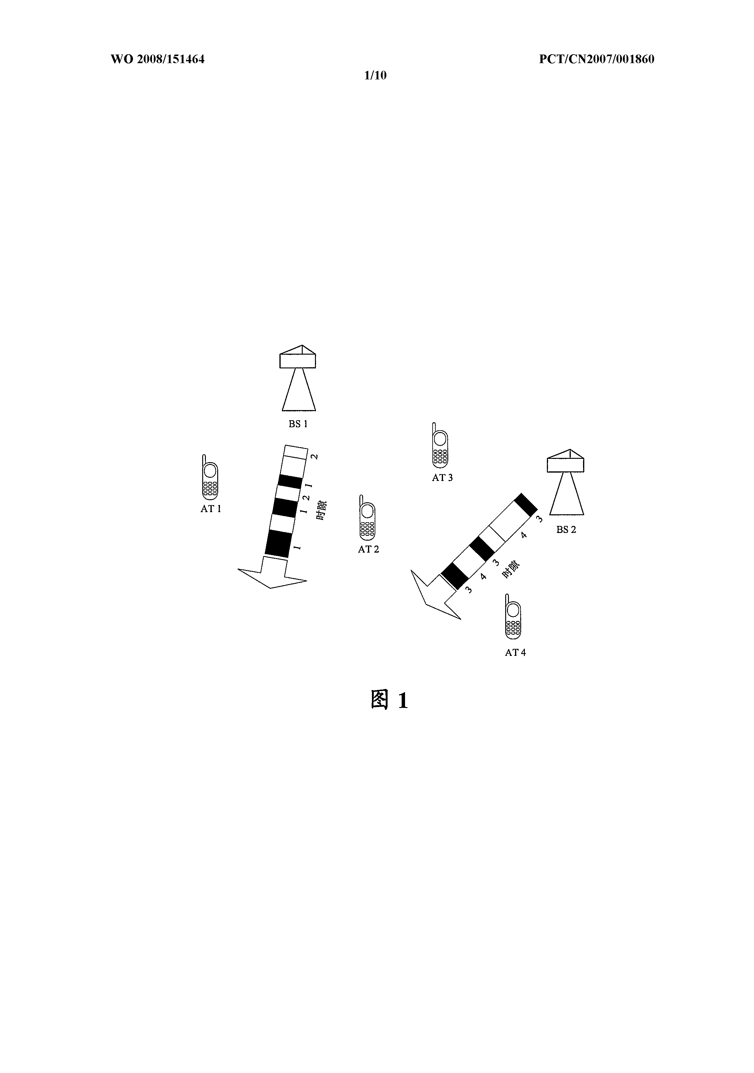
0002The agreement between EVDO and HSDPA is the integration and implementation of these technologies. It is increasingly used in practical commercial networks and is the upgrade path of the original CDMA system. The new network also requires wireless network emulation. The original Monte Carlo simulation algorithm does not incorporate emerging technologies, especially the new technology introduced in the downlink, and does not support the quality of service (QoS, Quality of Service) The processing of requirements, therefore, such simulation algorithms do not reflect well the performance and state of the actual work of the system. A schematic diagram of CDMA2000-1X EVDO forward channel time division multiplexing and user scheduling will be briefly described below, as shown in Figure 1: The forward channel acts as a "wide channel" for all users to share time. The smallest unit of time is the slot (slot). - a time slot may be assigned to a user to transmit data or assigned to an overhead message (called active slot), It is also possible to be idle and not send any data (called idle slot). Since the forward traffic channel is time-division multiplexed, which data is sent to which user at a certain time is determined by the scheduling procedure of the forward channel according to a certain scheduling policy, and different scheduling procedures will be used for the throughput of users in different wireless environments. Has a strong influence. The goal of scheduling is to make all users in the same cell as fair as possible and to maximize the total throughput of the cell. However, there is a contradiction between these two goals. For example, if the throughput rate of the entire cell is the largest, then the scheduling strategy should be to send data to the best terminal in the wireless environment. The inevitable consequence of this is that users at the edge are basically unable to get service. Therefore, in order to solve the problem of unfairness, the final scheduling algorithm will be a disappointment of these two goals. At present, the Proportional Fair Scheduler is a kind of algorithm that combines efficiency and fairness. The main principle of the algorithm is to track the following two variables: the current rate of application DRC (k), And the throughput T ( k ) of the user history, and scheduling according to the ratio DRC ( k ) /T ( k ). Therefore, it can be seen that the higher the rate of the current application, the more likely it is to get the service; the higher the user's historical throughput, indicating that it has previously received more service opportunities, then the probability of getting the service later is smaller. As mentioned above, wireless network simulation plays a key role in wireless network planning and optimization. If it can be used for the technical characteristics of CDMA2000-1X EVDO, Introducing the service QoS requirements, a wireless network simulation method is adopted to adapt the base station to adopt the forward scheduling technology, so that the wireless network simulation algorithm can better adapt to the requirements of the new air interface technology, further improve the simulation precision, and enable the wireless network simulation in the new network ( It is undoubtedly ideal to play a greater role in the planning and optimization of EVDO and HSDPA. However, the technology related to this has not yet been implemented. SUMMARY OF THE INVENTION The present invention has been made in view of the above problems, and it is a primary object of the present invention to provide a wireless network simulation simulation method. According to an embodiment of the present invention, a wireless network simulation simulation method is provided. The method includes the following processing: Step S402, Performing a snapshot cycle initialization; Step S404, performing a reverse link rate assignment process and a forward process flow; Step S406, Calculating a cell average throughput and an average rate based on QoS requirements of the service supported by the terminal; and step S408, In the case where the number of snapshot cycles does not reach the preset threshold, steps S402 to S406 are repeated. In step S406, if the services supported by the terminal have QoS requirements,
0003p
0004Calculate the average throughput of the forward cell by the following formula: Througput<sub>FL</sub> = ^ R<sub>F</sub>L , where P is the former
0005;·=]
0006The number of reverse access terminals, and l < p ≤ m; there is no QoS requirement for the services supported by the terminal.
0007^£)R ,.
0008Next, calculate the average throughput of the forward cell by the following formula: τ! draw gpt <sub>FL</sub> = ^——, where n - m is the number of forward access terminals; in addition, in the case where the service part supported by the terminal has QoS requirements, the average throughput of the forward cell is calculated by the following formula: where Ρ QoS<img file="WO2008151464A1_D0001.tif" />
0009The number of required front reverse access terminals, and l < p ≤ m, n - m is the number of forward access terminals without QoS requirements. Here, the forward average rate can be calculated by the following formula: DataRate^ = Throughput ^ / NumMobile , where NumMobile is the number of forward access users. And, the reverse average rate can be calculated by the following formula: DataRate^ = Throughput RL I NumMobile , where NumMobile is the number of reverse access users and is the reverse cell average throughput.
0010<img file="WO2008151464A1_D0002.tif" /> Specifically, in step S404, the reverse link rate assignment process includes: Step S702, All terminals are sorted according to the reverse QoS priority, the terminals of the high QoS priority service are placed in front of the sequence, the terminals of the QoS priority service are placed behind, and the terminals without QoS requirements are randomly placed at the end of the sequence; Step S704, performing data rate initialization on each terminal according to the access sequence of the terminal; step S706, Calculating a transmit power of the terminal traffic channel corresponding to the data rate, and calculating a total transmit power of the terminal; Step S708, Determining whether the total transmit power of the terminal exceeds the maximum transmit power threshold of the terminal; if the determination result is yes, proceeding to step S712, Otherwise, proceeding to step S710, Step S710, Determining whether the noise received by the relevant cell rises above a threshold due to the access of the i-th terminal, and if the determination result is yes, proceeding to step S712, Otherwise, the recording is successful for the terminal access; and in step S712, it is determined whether the data rate of the i-th terminal can be reduced. If the determination result is yes, the data rate is reduced by one level according to the rate level; otherwise, the terminal is recorded as a terminal. Access failed. After the data rate is reduced by one level in step S712, it is determined whether the degraded data rate is lower than the lowest rate threshold. If the determination result is no, the process returns to step S706. Otherwise, i has been recorded as a terminal access failure. In addition, in step S404, the forward processing flow includes: Step S802, Determining the total number of cells in the simulation range and the initial cell; Step S804; Determining the terminal that belongs to the initial cell; Step S806, sorting the terminal according to the forward service priority; Step S808, The terminal that does not meet the forward QoS requirement is filtered. Step S810, determining, according to the screening result of step S808, whether there is a terminal that cannot meet the forward QoS requirement, and if the determination result is yes, proceeding to step S812, Otherwise, proceeding to step S814; step S812, For the terminal that is unable to access the initial cell, the processing is performed; and the terminal sequence that can access the initial cell and the terminal that may be deleted are input, where the ordering in step S806 may be specifically as follows: Step S902 , The attributes of the terminal included in the snapshot are read one by one, and the service supported by the terminal is checked for priority requirements; Step S904, For a terminal without a priority requirement, it is assigned as a forward non-priority terminal set; step S906, For the priority-required QoS service terminal, it is assigned as a forward-priority terminal set; and in step S908, after traversing all the terminals, the terminals in the forward-priority terminal set are sorted according to priority, and juxtaposed At the front end of the terminal sequence, the terminals in the forward non-priority terminal set are randomly ordered and placed at the back end of the terminal sequence. At this time, step S908 may specifically include the following processing: Step S1002, Sorting the terminals of the cell according to the forward service priority; Step S1004, Let P=l, And determine the number of terminals with QoS requirements is M, Where M is an integer greater than or equal to 0; Step S1006, Determine if P is greater than M, If P is greater than M, output an accessible terminal sequence and a terminal sequence that cannot be accessed. If P is less than or equal to M, proceed to step S1008; Step S1008, The terminal of the former P QoS requirements is judged by the following formula, and the subsequent processing is performed according to the judgment result:
R FL-1 R
0012+ - FL-2 R
0013+ FL-p
0014+- < 1
DRC, DRC DRC
0016Formula 1 :
0017R FL-1 RR FL-p
0018+ - FL-2 + +■
DRC
0020Formula 2: <sup>DRC</sup>> <sup>DR</sup>°<sub>2</sub>
0021R FL-1 RR FL-p
0022+ - FL-2 + + - > 1
0023DRC„
0024Formula 3: <sup>DRC</sup>i <sup>DRC</sup>Wherein, in the case where the formula 1 is established, P=P+1 is caused, and the process proceeds to step S1006; in the case where the formula 2 is established, all terminals after the Pth terminal are placed in the terminal set that cannot be accessed. And outputting the terminal sequence that can be accessed and the terminal sequence that cannot be accessed; in the case that Equation 3 is established, the Pth terminal is placed in the terminal set that cannot be accessed, and P=P+1 is obtained. And the process proceeds to step S1006. In addition, between step S404 and step S406, In the case where forward adjustment is required, the forward adjustment algorithm is executed, or in the case where reverse adjustment is required, the reverse adjustment algorithm is executed. In addition, before step S402, the method further includes: calculating a forward DRC rate corresponding to the candidate set on each grid based on a comparison of the forward actual demodulation signal to noise ratio ϊθΓ /Ioc and the system demodulation threshold; According to the value of the actual signal-to-noise ratio ior /Ioc on each grid, the current raster corresponds to the forward DRC rate group that can be supported by different cells, and the actual for /Ioc value is between the demodulation thresholds corresponding to the two data rates. When in between, take a lower rate as the forward DRC rate that can be supported. Through the technical characteristics and introduction of QoS requirements for CDMA2000-1 X EVDO, The above technical solution of the invention makes the wireless network simulation algorithm more adaptable to the requirements of the new air interface technology, further improves the simulation precision, enables the wireless network simulation to greatly approximate the network condition of the new network (EVDO, HSDPA) system, and enables the wireless Network simulation plays a greater role in its planning optimization, which guides network planning and optimization more effectively. BRIEF DESCRIPTION OF THE DRAWINGS The accompanying drawings, which are set to illustrate,,,,,,,,,,,,,,,,,,,,,,,,,,,,,,,,,,,,,,,,,,,,,,,,,,,,,,,,,,,,,,,, In the drawings: FIG. 1 is a schematic diagram of channel time division multiplexing according to the related art; FIG. 2 is a general flowchart of a process for actually implementing a wireless network simulation simulation method according to an embodiment of the present invention; FIG. 3 is a process of FIG. FIG. 4 is a flowchart of a wireless network simulation simulation method according to an embodiment of the present invention; FIG. 5 is a processing flowchart of a first scheme of a wireless network simulation simulation method according to an embodiment of the present invention; 6 is a process flow diagram of a second scheme of a wireless network simulation method according to an embodiment of the present invention. 7 is a reverse link rate assignment procedure in a wireless network simulation method according to an embodiment of the present invention; FIG. 8 is a flowchart of forward processing in a wireless network simulation simulation method according to an embodiment of the present invention; It is a processing flowchart for prioritizing the forward traffic in the forward processing flow of FIG. 8; and FIG. 10 is a processing flowchart for filtering the forward-accessible terminal set in the forward processing flow of FIG. DETAILED DESCRIPTION OF THE INVENTION The present invention fully considers the technical features of AMC technology, physical layer hybrid HARQ technology mixing, rate control, especially the scheduling mechanism of a base station, and also considers hybrid service simulation processing with QoS requirements and no QoS (Quality of Service) requirements. A new network simulation method is proposed, which is simple and clear and can accurately reflect the changes of air interface technology. In general, in the present invention: First, for the characteristics of CDMA2000-1X EVDO forward channel full power transmission, the forward basic coverage static analysis is completed in the first stage of the simulation process; secondly, in the simulation process iteration process , complete the reverse basic coverage iterative analysis; again, for the QoS requirements of the current actual system services, In the simulation method, the demand discrimination and processing of QoS are introduced, and the reverse rate adjustment is performed according to the processing result. Finally, by processing the scheduling algorithm, a new algorithm is introduced to complete the calculation of the forward average rate and the cell throughput. Embodiments of the present invention will be described in detail below with reference to the accompanying drawings. As shown in FIG. 2, based on the principle of CDMA2000-1X EVDO forward channel time division multiplexing and user scheduling, combined with the network simulation algorithm, the processing for implementing the wireless network simulation method of the present invention includes: Step S201, Initialization of geographic information input and network configuration parameters: In this step, the initial work of the wireless network simulation is performed, which mainly includes importing a three-dimensional electronic map, and assigning initial values to the network including the base station, the terminal, the carrier, the bearer, etc., wherein The 3D electronic map includes at least elevation, and additional feature information and vector information such as roads and rivers. Step S202, Calculate the path loss of each cell: In this step, first, determine the range to be simulated; then, calculate the path loss of each cell in the specified range, and the grid refers to the minimum precision of the three-dimensional electronic map. The square is the smallest unit that can be divided into three-dimensional electronic maps; the specified range is determined by setting a certain path loss threshold. When the path loss of a cell on a certain grid exceeds this threshold, the distance between the grid and the cell is considered to be sufficient. Far from having to consider the impact of the community. The value of the path loss threshold is variable and is affected by factors such as the environment and network size. Step S203, Determining the candidate set and the strongest cell on each grid: The determination of the candidate set is based on the pilot signal to noise ratio of the relevant cell to each of the grids, wherein the pilot signal to noise ratio and each grid are relative to the respective cells The path loss is closely related. The CDMA2000-1X EVDO forward channel adopts full power transmission, that is, the power of the front pilot channel is also the total power of the forward transmission, and the pilot signal to noise ratio of the relevant cell to each grid can be calculated by the pilot transmission power and the path loss. After sorting from large to small, and comparing with the set candidate threshold, determining the coverage cell candidate set on each grid; after that, recording the most strong pilot signal to noise ratio cells in each grid, and in each cell The highest strong cell is recorded as the raster information of the cell, and this step is shown in FIG. Step S204, Calculating the forward DRC rate corresponding to the candidate set on each grid: Calculating the forward DRC rate of each CDMA2000-1X EVDO supported by each cell in the candidate set on each grid based on the coverage cell candidate set . The calculation of the DRC rate is based on a comparison of the forward actual demodulated signal to noise ratio ΙθΓ/loc and the system demodulation threshold. Different system demodulation thresholds correspond to different DRC rates. According to the value of the actual signal-to-noise ratio ΙθΓ/loc on each grid, the current raster corresponds to the forward DRC rate group that different cells can support. When the actual value of ΙθΓ/loc is between the two data rates corresponding to the demodulation gate P艮, the lower rate is taken as the forward DRC rate that can be supported. Step S205, Setting the terminal type and proportion: In order to facilitate the setting of traffic volume, in this step, the terminal type is set according to the terminal type and the bearer service-corresponding principle, and the terminal proportion is set according to the load of the service in the simulation target. Step S206, a network simulation process; step S207, The simulation map and statistical results are output, the network simulation ends; and finally, the processing ends. FIG. 3 is a process flowchart of determining the candidate set in the foregoing step S203, and the specific steps are as follows: Step S301, The pilot power Ppiloti from each cell on the current grid is calculated by:
0025..., - Ptx i * P thloss,
0026Ppiloti = <sup>3⁄4>ί</sup> ' , where i = 1 to] VI, <sup>Ρ</sup>",, · is the total power transmitted for the i-th cell; PathlosSi is the path loss of the cell to the current grid; M represents the number of cells associated with the current grid. For the actual network, there is a part of the cell away from a certain grid In the case of grid, the correlation is small and may not be counted. The processing method is to set a certain path loss threshold. When the path loss of a cell reaching the grid exceeds the threshold, the cell is considered to be the grid. It is irrelevant to determine the size of M. The path loss gate P艮 value is consistent with the gate P艮 value in step S202. Step S302, the total received power Ioj on the grid is calculated by the following formula:
M
0028I j = XP<sub>txJ</sub> * Pathloss<sub>i</sub>
0029i<sup>=1</sup> , where j is a raster marker. Step S303, The pilot signal to noise ratio Eci/Ioj of each cell on the grid j is calculated by the following formula: Ecj/Ioj = Ppilotj/Ioj. In step S304, Eci/Ioj is sorted (for example, in order from large to 'j). Step S305, the cell corresponding to the largest number of Ec/Io is set as the coverage cell candidate set located in the grid terminal: In this step, the value of the candidate set adopts a combination of the threshold value and the maximum limit. First, set the gate P艮 value of Ec/Io, and calculate the number of cells whose E/Ioj is greater than the threshold value is K. If K>N (N is the maximum number of candidate sets designed), the first N cells are taken as the candidate set, otherwise the first K cells are taken as the candidate set. Step S306, The raster information of the strongest cell is the cell in each cell is recorded. The strongest cell is defined as the cell that receives the largest Ec/Io value is the strongest serving cell of the grid. After that, the process ends. A wireless network simulation simulation method (i.e., a network simulation process in step S206) according to an embodiment of the present invention will be described in detail below with reference to the accompanying drawings. In general, the network simulation process consists of a large two-part cycle, including: snapshot process, a snapshot can be understood as a process in which the system reaches a steady state in a given distribution of a given terminal, the result of the simulation process is The results of a large number of snapshots are combined on average; and the iterative loop process, which consists of multiple iterations, which are designed to bring the system to a steady state. Previously, the iterative loop algorithm used in the related art was The Monte Carlo iterative algorithm is used for both forward and reverse. However, in the DO system, the forward resource is time-division multiplexed, so the Monte Carlo iterative algorithm is not applicable. The forward algorithm in this embodiment is no longer used. Monte Carlo iterative algorithm is adopted, but a new algorithm considering forward scheduling and QoS is adopted. At the same time, based on the Monte Carlo iterative algorithm, based on the QoS and forward matching, the common inverse is adopted. Improved to the algorithm #文. Below ^! The implementation of the method is described in detail. As shown in FIG. 4, the wireless network simulation and simulation method according to this embodiment includes the following processing: Step S402, Performing a snapshot loop initialization; step S404, Performing a reverse link rate assignment process and a forward process flow; step S406, Calculating a cell average throughput and an average rate based on QoS requirements of the service supported by the terminal; and step S408, If the number of snapshot cycles does not reach the preset threshold, step S402 to step S406 are repeated. The method can be implemented by two schemes, and the following two schemes are described separately. The first scheme is shown in FIG. 5. In this solution, the wireless network simulation method specifically includes the following processing: Step S501, Snapshot loop initialization: The initialization includes the following contents: (1) determining the location of the terminal randomly distributed in a predetermined manner, and randomly distributing the terminal within a specified geographical range in the network (for example, according to the cell coverage area, the sub-cell distribution) Traffic, etc.) Once the distribution pattern is determined, the specific location of the terminal in each snapshot will be randomly determined. The number of terminals in each snapshot conforms to the Poisson distribution principle.
0030(2) determining an associated cell (overlay cell candidate set) according to the grid where the terminal is located; (3) determining random log normal fading and random power control error information of each terminal. Step S502, Reverse link rate assignment (as shown in Figure 7); step S503, The terminal sequence that can be reversely accessed in the reverse iteration result is used as an input condition, and the forward processing flow (shown in FIG. 8) is performed, thereby obtaining a terminal sequence that can simultaneously satisfy the forward access condition. Step S504, It is judged whether or not reverse adjustment is required, and if necessary, step S505 is performed; if not, step S506 is performed. Here, it is worth noting that, in the decision process, if a terminal is deleted in the cell forward processing flow in step S508, the terminal is deleted from the reverse iterative terminal set, and as long as there is at least one terminal If it is deleted, you need to perform a reverse adjustment. Step S505, Performing a reverse rate adjustment algorithm, the reverse adjustment algorithm and the reverse link rate assignment (as shown in FIG. 7) are basically the same, except that the terminal is not randomly selected, and the terminal set is clear, that is, from Selected in the reverse iteration, but excluding the terminal deleted in the forward processing flow; step S506, Calculate pre-, reverse throughput and average rate. In this step, the calculation of the forward average throughput of the cell is divided into the following cases: Case 1: In the case that the services supported by the terminal have QoS requirements, the average throughput of the forward cell is calculated by the following formula: , where p Forward reverse access terminal<img file="WO2008151464A1_D0003.tif" />
0031Number of cases, and Kp ≤ m; Case 2: In the case where the service supported by the terminal does not have QoS requirements, J DRC is calculated by the following formula<sub>i</sub>
0032Calculate the average throughput of the forward cell: Througput<sub>FL</sub> = ^ , where n - m is the forward access end n - m
0033The number of terminals; and Case 3: In the case where the service part supported by the terminal has QoS requirements, the average throughput of the forward cell is calculated by the following formula: Througput<sub>FL</sub> , among them, <img file="WO2008151464A1_D0004.tif" /> =<sub> 1</sub>— id— , where,<sub>p</sub>For Q<sub>oS</sub>The number of required reverse access terminals, and l<p≤m, =1 DRC,
0034n - m is the number of forward access terminals without QoS requirements. The forward average rate in all three cases is equal to the forward cell average throughput divided by the number of forward access users. Therefore, the forward average rate can be calculated by the following formula:
0035DataRate<sub>Ra</sub> = Throughput <sub>FL</sub> I NumMobile , where NumMobile is the number of forward access users. Also, the inverse average rate can be calculated by the following formula: DataRate^ = Throughput^ / NumMobile , where NumMobUe is the number of reverse access users, k
0036And Througput^ = ^ , Througput is the reverse cell average throughput.
0037/=1 Step S507, Determine whether the number of snapshot loops reaches the preset threshold. If the number of times is insufficient, continue to the next snapshot; otherwise, end all snapshot loops. The variable initial values of the different snapshot loops are different. The variables include the number of terminals, the location of the terminal, and the access sequence of the terminal. Step S508: The processing ends. The above is a description of the first aspect of the present embodiment. In addition, in the actual implementation, the following second solution may also be provided. The second embodiment will be described below with reference to the accompanying drawings. The second solution: as shown in FIG. 6, in the solution, the wireless network simulation method specifically includes the following processing: Step 601, performing a snapshot loop initial step 602, Forward processing flow (as shown in Figure 8); Step 603, The terminal sequence that can be forward-accessed after the forward processing is used as an input condition, and the reverse link rate assignment is performed (as shown in FIG. 7), thereby obtaining a terminal sequence that can simultaneously satisfy the reverse access condition. Step 604, Determine whether forward adjustment is needed, and if necessary, perform step 605. If not, go to step 606. For the judgment condition, similar to the first scheme described above, if the terminal in the cell reverse link rate assignment process in step 603 cannot reverse access, the terminal is deleted from the forward terminal set. And, as long as at least one terminal is deleted, it is necessary to perform a forward adjustment algorithm. Step 605, Performing the forward adjustment algorithm, the forward adjustment algorithm and the forward processing flow (as shown in Figure 8) are basically the same, except that the terminal is not randomly selected, and the terminal set is clear, that is, it is selected from the forward processing flow. , but does not include the terminal that was deleted in the reverse link rate assignment process. Step 606, calculating pre- and reverse throughput and average rate; step 607; Determine whether the number of snapshot cycles reaches the preset threshold; finally, the processing flow ends. Fig. 7 shows the reverse path rate assignment flow in step S404 (i.e., step S502 or S603). As shown in FIG. 7, the method mainly includes the following steps: Step 1: Sort all the terminals according to the reverse service QoS priority, and the terminal of the high priority service is placed in front of the sequence, and the terminal of the priority service is placed after the terminal. The terminal without QoS requirement is randomly placed at the end of the sequence, and after the terminal reverse access sequence is determined, it will remain valid in each reverse iteration calculation of the current snapshot; (corresponding to step S702 above) According to the terminal access sequence, the data rate is initialized for each terminal, and the initial rate of the terminal is usually set to the highest rate of the system, and the data rate of the i-th terminal is set; (for step S704 with the above), step 3 Calculating the transmission power of the terminal traffic channel corresponding to the rate; Step 4, Calculating the total terminal transmit power Txi according to the proportion of the traffic channel in the total transmit power of the terminal; (Step 3 and Step 4 correspond to the above step S706) Step 5, determining whether Txi exceeds the maximum transmit power threshold of the terminal i, if it is determined to be , step 7 is performed; otherwise step 6 is performed; (corresponding to step S708) step 6, Determining whether the noise received by the relevant cell exceeds the threshold due to the access of the i-th terminal, if the determination is yes, step 7 is performed; otherwise, step 10 is performed. Record that the terminal can successfully access; (corresponding to step S710 above), step 7, Determining whether the data rate of the terminal i can be reduced. Here, the main basis of the judgment is that if the service required by the terminal i requires the data rate to be a fixed value, the rate cannot be lowered, and step 10 is performed. Recorded as terminal access failure, otherwise go to step 8; Step 8, According to the rate class, one level will be lowered; (Steps 7 and 8 correspond to the above steps - S712) Step 9: Determine whether the rate level is lower than the minimum rate threshold after the rate level is lowered. If the judgment is yes, the terminal cannot access. , go to step 10, Recorded as terminal access failure; otherwise, go to step 3. Carry out the next iteration; Step 10, Record the calculation result of the terminal; Step 11 Perform a loop of the next terminal until the reverse rate assignment of all terminals is judged; Step 12 It is judged whether the reverse link satisfies the end decision condition of the current snapshot. If the determination is yes, step 13 is performed; otherwise, step 3 is performed. Step 13, The final result is output, ie, the reverse access terminal sequence and the reverse access rate. Step 14, End this snapshot loop. For the decision condition in step 12, determining whether a snapshot ends is usually divided into two phases. When the convergence condition is met, for example, the cell reverse noise floor noise increase of the adjacent two iterations is less than a certain threshold. That is, when the fluctuation of the inverse bottom noise rise of two adjacent iterations is small, it is considered that the iteration converges and exits the iterative loop. When the iteration does not converge, but the number of iterations is relatively large, in order to prevent the iteration from converge, the loop cannot be stopped. Set the threshold of the number of iterations. When the number of iterations is equal to this threshold, iteratively terminates the iteration and transfers to the next snapshot loop. FIG. 8 shows the forward processing flow in the step S404 (ie, step S503 or step S602). As shown in FIG. 8, the method includes the following steps: Step 80: Set the total number of cells in the simulation range to Ncell; (corresponding to step S802 above), step 81; Determining that the initial cell is cell X, x=l ; Step 82, Determining a terminal subordinate to the initial cell X; (Step 81 and Step 82 correspond to the above step S804) Step 83, Sorting the terminals belonging to the cell X according to the forward service priority (the specific process of sorting is as shown in FIG. 9); (corresponding to the above step S806), step 84, Screening the terminal that cannot meet the forward QoS requirement (the specific processing flow of the screening is shown in FIG. 10;); (corresponding to the above step S808), step 85; Determining whether there is a terminal that cannot meet the forward QoS requirement, according to the screening result of step 84, determining whether it is necessary to process the terminal that cannot satisfy the forward QoS requirement, if yes, executing step 86; if not, executing step 87; (corresponding to step S810 above), step 86, For the processing of the terminal that cannot access the cell x in the forward direction, here, the processing method may have various options, for example: (1) deleting such terminals directly from the terminal sequence; (2) selecting from the candidate set of these terminals The cell with the second highest strength belongs to the cell, and if there is no candidate set cell with the second pilot strength, the terminal is deleted from the reverse iteration result, wherein, preferably, the ^^ class is used. a method of deleting the terminal directly from the terminal sequence; (corresponding to step S812 described above), step 87, Outputting a sequence of terminals that can be accessed and possibly terminals to be deleted (corresponding to step S814 above); Step 88, x = x+1. Step 89, Determine whether X is less than or equal to the number of cells Ncell, If the determination is yes, it means that there is still a cell unprocessed, go to step 82; otherwise, the process flow ends. The processing flow for prioritizing the forward traffic according to the forward snapshot service in the result of the reverse snapshot loop in step S806 (i.e., step 83) is shown in FIG. As shown in FIG. 9, the method includes the following steps: Step S902: Read the terminal attributes included in the snapshot one by one, and check whether the service supported by the terminal has a priority requirement; Step S904, For a normal terminal without priority requirements, it is assigned as a forward non-priority terminal set; step S906, For the QoS service terminal with the priority requirement, it is assigned as the forward priority set of terminals; Step S908, After traversing all the terminals, the terminals in the priority terminal set are sorted according to the priority, and placed at the front end of the terminal sequence, and the terminals in the forward non-priority terminal set are randomly sorted and placed in the terminal sequence. End, thus determining the access sequence of all terminals in this snapshot; Finally, the processing flow ends. The flow of screening the forward-accessible terminal set in step S808 (i.e., step 84) is illustrated in FIG. As shown in FIG. 10, the method includes the following steps: Step S1002: The terminal of the cell is sorted according to the forward service priority, and the number of terminals that cannot be accessed is 0. Here, it can be assumed that there are n terminals belonging to the cell i, and the order of priority from high to low is ATi,
0038AT<sub>2</sub> AT„, its DRC rate is recorded as DR, DRC<sub>2</sub> DRC<sub>n</sub>. Where ΑΤι to AT<sub>M</sub>Belong to the set of forward-priority terminals, the rate of QoS requirements is recorded as RFL to R<sub>F</sub>L-m, and AT<sub>m+1</sub>To eight! ^ belongs to the forward non-priority terminal set. Step S1004, setting P = l; the number of terminals having QoS requirements is M, the step is mainly for initializing the calculation; Step S1006, determining whether P is greater than M, and if P is greater than M, the process proceeds to step S1010. If P is less than or equal to M, the process proceeds to step S 1008, where P is greater than M, indicating that all terminals with QoS requirements have been scanned, and the terminal without QoS requirements does not need to determine whether the requirement is met; Step S1008, P terminals with QoS requirements determine whether the following formula is true;
R FL-1 R
0040+ - FL-2 R
0041+ FL-p
0042+ - < 1
DRC, DRC, DRC
0044Formula 1 :
0045R FL-1 RR FL-p
0046- + - FL-2 + + -
0047DRC.
0048Formula 2: <sup>DRC</sup>> <sup>DRC</sup><sub>2</sub>
0049RFL-1 I RFL-2 IR FL-p
0050+- > 1
0051DRC„
0052Formula 3: <sup>DRe</sup>, <sup>DRC</sup>^ Here, it should be noted that in Equation 1, Equation 2, and Equation 3, the left-side accumulation needs to delete the terminal that has been in the terminal set that cannot be accessed in the forward direction; when the formula 1 is satisfied, That is, when the sum of the sums is less than 1, it indicates that the forward terminal can carry the P terminal and the previous terminal and there is also a rich capacity to carry the non-QoS terminal. At this time, P=P+1 is performed, and the process proceeds to step S1006; if, the formula 2 is established, that is, when the accumulated sum is equal to 1, it indicates that the P terminal and the previous QoS terminal can just be carried in the forward direction, and cannot carry any other terminal at the same time, regardless of whether there is QoS requirement, at this time, all terminals after the terminal P If a set of terminals that cannot be accessed is included, including QoS and no QoS requirements, the process proceeds to step S1010 (outputting an accessible terminal sequence and a terminal sequence that cannot be accessed;). When the formula 3 is satisfied, that is, when the accumulated sum is greater than 1, it indicates that the terminal P cannot be accessed, and the terminal P needs to be placed in the set of terminals that cannot be accessed in the forward direction. At this point, the terminal after P has access to it, so do not exit the loop and execute P=P + 1 . The process proceeds to step S 1006; step S 1010, The terminal sequence that can be accessed and the terminal sequence that cannot be accessed are output, and the sum of the two is the total number of terminals in the cell at the start of processing. Finally, the process ends. The specific implementation steps of the present invention will be described in detail below with reference to FIG. 2, taking a simulation flow of a CDMA2000-1X EVDO network as an example. The specific implementation steps are as follows:
0053(1) Import 3D electronic maps, including elevation, features and vector information. Enter the base station, terminal, carrier, power, and other information of the network in batches or one by one.
0054(2) Taking the general urban environment as an example, usually, when the path loss of a certain point reaches 200 dB, it is considered that the point is far enough away from the cell that transmits the signal. Therefore, setting 200 dB as the threshold, and calculating the path loss of each cell is less than or equal to The path loss of all the grids around the threshold and the path loss matrix of each cell.
0055(3) Calculating the pilot signal to noise ratio Ec Ioj of each grid relative to each cell, where is the pilot energy per chip from the i th cell, and Ioj is the total received power on the grid.
M
0057Where i = l M, i=i , Μ = 20 (in an urban environment) In this step, the values of the pilot signal-to-noise ratios calculated on each grid are sorted, and the largest one is selected. As an alternative set of coverage cells located at the grid terminal, usually Ν = 6. For the one with the largest pilot signal to noise ratio in the coverage cell candidate set, the corresponding grid of its corresponding cell, that is, the path loss file matrix of the strongest serving cell is marked. (4) Calculate the forward demodulation signal-to-noise ratio of each grid<sup>Io</sup>r/I<sub>Oc</sub> The maximum rate DRC that each grid can support is obtained by querying Table 1 below. The following is the correspondence between the forward demodulation SNR threshold and the DRC rate under Additive White Gaussian Noise (AWGN) conditions:
0058<img file="WO2008151464A1_D0005.tif" />
0059Table 1 Table 1 is from the minimum test standard "Recommended Minimum Performance Standards for cdma2000 High Rate Packet Data Access Terminal".
0060(5) Assuming that the QoS requirements for the data rate supported by the network are 1.2 Mbps, 300 kbps, and 112 kbps, and the ratio of services is 1: 2: 1, three types of terminals are set to correspond to the three types of services, and three types. The ratio of the number of terminals is also 1: 2:1. Even if a certain terminal can support multiple services, it is set separately in the simulation to facilitate the distribution of traffic.
0061(6) Initialize the snapshot parameters, including the number of terminals, the distribution location, and so on.
0062(7) performing reverse rate assignment (as shown in FIG. 6), determining the reverse access order of the terminal according to the QoS priority of the service supported by the terminal, and iteratively determining the reverse access rate of each terminal in the terminal access sequence and The failure message, and the terminal sequence that was successfully accessed in reverse.
0063(8) In the terminal that determines the reverse successful access, whether the forward direction needs to support the service with the QoS requirement, if not, jump directly to (11), calculate the average reverse cell average throughput; if the judgment is yes, Then execute (9).
0064(9) Here, the forward QoS requirement processing algorithm is described in the process of one snapshot by a certain assumption condition. Assume that there are six terminals that are successfully accessed in the reverse direction. According to whether the forward service has QoS requirements and the priority of the QoS is sorted from high to low, the terminal sequence AT!, AT is obtained.<sub>2</sub> AT<sub>6</sub>. Set AT! to AT<sub>4</sub>Is a terminal with QoS requirements in the forward direction, AT<sub>5</sub>And AT<sub>6</sub>It is a common service terminal without QoS requirements, as shown in Table 2 below:
0065<img file="WO2008151464A1_D0006.tif" />
0066Table 2 Substituting the above assumptions into Equation 1 to Equation 3, you can get:
0067<img file="WO2008151464A1_D0007.tif" />
0068200 500 100 300
0069■ + + + ·
00701228.8 2457.6 307.2 921.6
0071« 1.0173
0072> 1 where, when p = 3, there is FL-1 I FL I FL
0073DRC, DRC<sub>2</sub> DRC<sub>3</sub>
0074200 500 100
0075― 1228.8 2457.6 307.2
0076« 0.692
0077< 1 Therefore, in order to satisfy the three terminals AT with high priority of the forward service, to the AT<sub>3</sub>QoS requirements, not allowed for AT<sub>4</sub>Forward access. At the same time, due to AT to AT<sub>3</sub>After the access does not make the forward capacity saturated, it can still access the ordinary terminal AT.<sub>5</sub>And AT<sub>6</sub>, ie, the final forward access terminal sequence is AT AT<sub>2</sub>AT<sub>3</sub>AT<sub>5</sub>And AT<sub>6</sub>composition.
0078(10) The terminal sequence of the reverse access is used as the terminal sequence of the reverse access, and the iteration of the reverse rate assignment is performed again. Assume that the reverse terminal rate after iteration is shown in Table 3 below:<img file="WO2008151464A1_D0008.tif" />
0079table 3
0080(1 1) Calculating the average throughput of the reverse cell before the calculation: According to the assumptions of Table 2 and Table 3, the third case is combined, that is, the access terminal sequence is a union of the terminal having the QoS service forward and the terminal without the QoS.
0081Y<sub>J</sub>DRC<sub>i</sub>
0082Bring the values in Table 2 into the formula 73⁄4raMs?Mt<sub>F</sub> = ^ + , can get the first n - m ― ;=1
0083Average cell throughput:
0084Througput<sub>FL</sub> = ^ * β FL-i
0085/'=1
0086<img file="WO2008151464A1_D0009.tif" />
00873072k + l 53.6k
0088* (1— 0.692) + (200k + 500k + 100k)
00892
0090= S70.96kbps Bring the values in Table 3 into the formula! 3⁄4'0^/^<sub>3⁄4</sub> =∑R<sub>RL</sub>-<sub>l</sub> , you can get the reverse average block swallow
0091(=1
0092Volume: <img file="WO2008151464A1_D0010.tif" />
0093= Ί6Μ + 307.2A: + 76M + 153.6A: + 38.4Λ
0094= 652Mbps
0095(12) Reverse average rate before calculation: Forward average rate = forward cell average throughput I number of forward access users
0096= 870.96k/5 = 174.192kbps Reverse average rate = reverse cell average throughput I number of reverse access users
0097= 652.8k/5
0098= 130.56kbps
0099(13) Determine whether the number of snapshot cycles reaches a preset threshold. If the number of times is not enough, change the initial variable of the snapshot loop, that is, change the number of terminals, location, access order, etc., and continue the next snapshot. Otherwise, end all snapshot loops.
0100(14) Statistically average the results of all snapshot cycles, output the simulation graph, and end the simulation. In summary, the present invention is directed to CDMA2000-1X EVDO air interface technology features such as forward full power transmission, forward partial service QoS requirements, forward traffic demand scheduling, rate control, etc. Iterate the process and introduce the processing method for the QoS-required service. At the same time, the dynamic scheduling strategy is simulated by the approximate static method, which solves the defect that the traditional simulation method can not get the forward average rate and the average cell throughput. By means of the technical solution of the invention, the wireless network simulation can be greatly approximated to the network condition of the actual EVDO system, and the EVDO network planning and optimization work can be guided more efficiently. The above is only the preferred embodiment of the present invention, and is not intended to limit the present invention, and various modifications and changes can be made to the present invention. Any modifications, equivalent substitutions, improvements, etc. made within the spirit and scope of the present invention are intended to be included within the scope of the present invention.
Contents7
24 sheets
Sheet 1 Sheet 2 Sheet 3 Sheet 4 Sheet 5 Sheet 6 Sheet 7 Sheet 8 Sheet 9 Sheet 10 Sheet 11 Sheet 12 Sheet 13 Sheet 14 Sheet 15 Sheet 16 Sheet 17 Sheet 18 Sheet 19 Sheet 20 Sheet 21 Sheet 22 Sheet 23 Sheet 24
Every citation, both ways
| Document | Relation | Office | Category | Cited during |
|---|---|---|---|---|
| US10791566B2 | Cited by | United States of America | – | Applicant |
| US10212026B2 | Cited by | United States of America | – | Applicant |
| US10004082B2 | Cited by | United States of America | – | Applicant |
| US10749737B2 | Cited by | United States of America | – | Applicant |
| US10117111B2 | Cited by | United States of America | – | Applicant |
| US12316437B2 | Cited by | United States of America | – | Applicant |
| US10880000B2 | Cited by | United States of America | – | Applicant |
| US11496212B2 | Cited by | United States of America | – | Applicant |
| US9800460B2 | Cited by | United States of America | – | Applicant |
| US10548025B2 | Cited by | United States of America | – | Applicant |
| US11936466B2 | Cited by | United States of America | – | Applicant |
| US10461846B2 | Cited by | United States of America | – | Applicant |
| CN111352728A | Cited by | China | – | Search report |
| CN1845630A | Cites | China | A | International search |
| JP2004241800A | Cites | Japan | A | International search |
| US2005195749A1 | Cites | United States of America | A | International search |
6 members in 3 offices
Members6
| Document | Office | Kind | |
|---|---|---|---|
| WO2008151464A1This record | World Intellectual Property Organization (WIPO) | A1 | |
| WO2008151464A8 | World Intellectual Property Organization (WIPO) | A8 | |
| CN101653021A | China | A | |
| EP2169968A1 | European Patent Office (EPO) | A1 | |
| CN101653021B | China | B | |
| EP2169968A4 | European Patent Office (EPO) | A4 |
5 legal events, as 2 offices reported them to INPADOC
Over the term
Point at a mark for the eventEvents
| Event | Code | Office | |
|---|---|---|---|
| Wipo information: entry into national phaseWWE | WWE | WO | |
| Wipo information: entry into national phaseWWE | WWE | WO | |
| Non-entry into the national phaseNENP | NENP | DE | |
| Ep: the epo has been informed by wipo that ep was designated in this application121 | 121 | WO | |
| Wipo information: entry into national phaseWWE | WWE | WO |
Numbers
- Publication
- 2008/151464
- Application
- 1860
Titles2
- English
- A WIRELESS NETWORK SIMULATION METHOD
- French
- PROCÉDÉ DE SIMULATION DE RÉSEAU RADIO
Classification
- CPC, 3
- H04W16/22
- H04L43/0888
- H04L43/16
- IPC, 1
- H04W16 22
Designated states4
- Regional, 4
- Zimbabwe
- Turkmenistan
- Türkiye
- Togo