Interoperability gateway for land mobile radio system
Summary by NHIP
LMR Interoperability Gateway
The gateway system provides backup connections between a dispatch console and disconnected Land Mobile Radio sites using dynamically assigned control stations. Each station utilizes specific radios linked to distinct frequency channels to monitor and transmit voice calls for designated talk groups.
Claim Score by NHIP
Abstract
Disclosed is an interoperability gateway system that provides backup connection between a dispatch center and a Land Mobile Radio (LMR) system in the event the dispatch center is disconnected from the LMR system. In general, this may be accomplished by providing an RF link between the disconnected site and the interoperability gateway via a controller, or interoperability site network interface (ISNI), that is activated when the dispatch center is disconnected from the LMR system. The interoperability gateway provides the backup connection by allocating a control station for each channel available at the disconnected LMR system. When compared to conventional dispatch console backup schemes, the disclosed interoperability gateway system greatly reduces the equipment needed to provide dispatch console backup, thereby decreasing equipment and operation costs, and simplifying operation by providing a solution that is virtually transparent to the dispatcher.
Term
8.9 yearsleft in the term
Expires 31 July 2035.
- Priority
- Filed
- Granted
- Today
- Expires
14 claims: 3 independent, 11 dependent
- 1A gateway system for providing backup connection between a console of a dispatch center and a Land Mobile Radio (LMR) system comprising a plurality of LMR sites when a connection between the console of the dispatch center and at least one of the LMR sites is disconnected, the gateway system comprising:a plurality of control stations comprising: at least a first control station dynamically assigned a first voice channel by a controller and configured to monitor voice calls received on the first voice channel and to transmit voice calls on the voice channel for a first plurality of talk groups;at least a second control station dynamically assigned a second voice channel by the controller and configured to monitor voice calls received on the second voice channel and to transmit voice calls on the second voice channel for second plurality of talk groups;anda third control station assigned a control channel and configured to monitor and transmit control data on the control channel for the first plurality of talk groups and the second plurality of talk groups;wherein the first control station comprises a first radio associated with at least a first radio frequency channel, wherein the second control station comprises a second radio associated with at least one of the first radio frequency channel and a second radio frequency channel, and wherein the third control station comprises a third radio associated with at least a third radio frequency channel,wherein the first radio, the second radio, and the third radio are in communication with the controller via an internet protocol (IP) network,wherein the first control station is configured to transmit and receive voice calls placed on at least one talk group of the first plurality of talk groups by a plurality of service radios communicating with the at least one disconnected LMR site, and wherein the second control station is configured to transmit and receive voice calls placed on at least one talk group of the second plurality of talk groups by the plurality of service radios communicating with the at least one disconnected LMR site,wherein the first control station and the second control station are configured to transmit and receive the voice calls between the at least one disconnected LMR site and the console of the dispatch center,wherein the first control station is configured to transmit and receive the voice calls placed on the at least one talk group of the first plurality of talk groups by the plurality of service radios via a first wireless radio frequency communication link between the console of the dispatch center and the at least one disconnected LMR site, and wherein the second control station is configured to transmit and receive the voice calls placed on the at least one talk group of the second plurality of talk groups by the plurality of service radios via at least one of the first wireless radio frequency communication link and a second wireless radio frequency communication link between the console of the dispatch center and the at least one disconnected LMR site;wherein at least one of the first wireless radio frequency communication link and the second wireless radio frequency communication link is configured to terminate in response to the reconnection of the wired connection between the console of the dispatch center and the at least one disconnected LMR sitewherein the controller is configured to detect disconnection of the wired connection between the console of the dispatch center and the at least one disconnected LMR site and to assign the first voice channel to the first control station and to assign the second voice channel to the second control station and to assign the control channel to the third control station, andwherein the controller is configured to provide an interface between the gateway system and the console of the dispatch center, wherein the console includes one or more consoles.
- 6Broadest claimClaim Score 14, narrow(NHIP)A system for providing backup connection between a console of a dispatch center and a Land Mobile Radio (LMR) system comprising a plurality of LMR sites when a connection between the console of the dispatch center and at least one of the LMR sites is disconnected, the system comprising:a controller configured to receive an indication that the connection between the console of the dispatch center and the at least one disconnected LMR site is disconnected;a set of control stations, comprising at least a first control station, a second control station and a third control station,wherein the first control station comprises at least a first radio associated with at least a first radio frequency channel and wherein the second control station comprises at least a second radio associated with at least a second radio frequency channel,wherein the first radio and the second radio are in communication with the controller via an internet protocol (IP) network,wherein the first control station is configured to establish a first wireless radio frequency communication link between the console of the dispatch center and the at least one disconnected LMR site via the first radio frequency channel and wherein the second control station is configured to establish a second wireless radio frequency communication link between the console of the dispatch center and the at least one disconnected LMR site via the second radio frequency channel,wherein the first control station is configured to transmit and receive voice calls placed on at least a first plurality of talk groups by a first subset of a plurality of service radios communicating with the disconnected at least one of LMR site and wherein the second control station is configured to transmit and receive voice calls placed on at least a second plurality of talk groups by a second subset of the plurality of service radios communicating with the disconnected at least one of LMR site,wherein the third control station comprises at least a third radio associated with at least a third radio frequency channel and is configured to transmit or receive control data on a control channel placed on the control channel by at least one of the at least one disconnected LMR site and the console of the dispatch center for at least the first subset of the plurality of talk groups and the second subset of the plurality of talk groups,wherein the first control station and the second control station are configured to transmit and receive the voice calls between the at least one disconnected LMR site and the console of the dispatch center, andwherein the first control station is configured to transmit and receive the voice calls placed on the first subset of the plurality of talk groups via the first wireless radio frequency communication link between the console of the dispatch center and the at least one disconnected LMR site and wherein the second control station is configured to transmit and receive the voice calls placed on the second subset of the plurality of talk groups via the second wireless radio frequency communication link between the console of the dispatch center and the at least one disconnected LMR site;center, andwherein the first control station is configured to transmit and receive the control signals placed on the control channel via the second wireless radio frequency communication link between the console of the dispatch center and the at least one disconnected LMR site.
- 12A method for providing backup connection between a console of a dispatch center and a Land Mobile Radio (LMR) system comprising a plurality of LMR sites when a wired connection between the console of the dispatch center to at least one of the LMR sites is disconnected, the method comprising:detecting the disconnection of the wired connection between the console of the dispatch center and the at least one disconnected LMR site;establishing, via at least a first control station and a second control station, a first communication link and a second communication link between the console of the dispatch center and the at least one disconnected LMR site, wherein the first control station comprises a first radio associated with at least a first radio frequency channel and wherein the second control station comprises a second radio associated with at least a second radio frequency channel,wherein the first radio and the second radio are in communication with a controller via an internet protocol (IP) network,wherein establishing the communication link comprises establishing, by the first control station, a first wireless radio frequency communication link between the console of the dispatch center and the at least one disconnected LMR site via the first radio frequency channel and establishing, by the second control station, a second wireless radio frequency communication link between the console of the dispatch center and the at least one disconnected LMR site via the second radio frequency channel;andallocating, in response to detecting the disconnection, the first control station as a first voice channel for communicating with the at least one disconnected LMR site over the first voice channel and the second control station as a second voice channel for communicating with the at least one disconnected LMR site over the second voice channel, wherein the first control station is configured to transmit and receive a first set of voice calls placed on at least a first subset of a plurality of talk groups by a plurality of service radios communicating with the at least one disconnected LMR site and wherein the second control station is configured to transmit and receive a second set of voice calls placed on at least a second subset of a plurality of talk groups by the plurality of service radios communicating with the at least one disconnected LMR site,wherein the first control station is configured to transmit and receive the first set of voice calls between the at least one disconnected LMR site and the console of the dispatch center and wherein the second control station is configured to transmit and receive the second set of voice calls between the at least one disconnected LMR site and the console of the dispatch center,wherein the first control station is configured to transmit and receive the first set of voice calls placed on the first subset of the plurality of service radios via the first wireless radio frequency communication link between the console of the dispatch center and the at least one disconnected LMR site and wherein the second control station is configured to transmit and receive the second set of voice calls placed on the second subset of the plurality of service radios via the second wireless radio frequency communication link between the console of the dispatch center and the at least one disconnected LMR site, andwherein the first wireless radio frequency communication link and the second wireless radio frequency communication link are configured to terminate in response to reconnection of the wired connection between the console of the dispatch center and the at least one disconnected LMR site.
Independent claims3
65 paragraphs in 6 sections, as filed
CROSS-REFERENCE TO RELATED APPLICATIONS
Pursuant to 35 U.S.C. § 119(e), this application claims the benefit of, and hereby incorporates by reference for all purposes, U.S. Pat. No. 9,800,460, entitled “Interoperability Gateway for Land Mobile Radio System,” filed Jul. 31, 2015, and naming Arindam Roy, Brandon Hudson Yarbrough, Jon Bartosch, and Steve Newman as inventors as well as U.S. Provisional Patent Application Ser. No. 62/032,376, entitled “Interoperability Gateway for Land Mobile Radio System,” filed Aug. 1, 2014, and naming Arindam Roy, Brandon Hudson Yarbrough, Jon Bartosch, and Steve Newman as inventors.
FIELD
The present disclosure relates generally to Land Mobile Radio (LMR) communication systems. More specifically, but not by way of limitation, the present disclosure relates to a system for providing backup connection between a dispatch center and an LMR system in the event the dispatch center is disconnected from the LMR system.
BACKGROUND
The statements in this section merely provide background information related to the present disclosure and may not constitute prior art.
Land Mobile Radio (LMR) systems are deployed by organizations requiring instant communication between geographically dispersed and mobile personnel. Current LMR systems can be configured to provide for radio communications between one or more sites and subscriber radio units in the field. A subscriber radio unit (hereinafter “radio”) may be a mobile unit or a portable unit. LMR systems can be as simple as two radio units communicating between themselves over preset channels, or they can be complex systems that include hundreds of radio units and multiple sites. Typical users of LMR systems include police departments, fire departments, medical personnel, security personnel, EMS, and the military.
LMR systems are usually connected to a dispatch center, which provides functionality for call routing and interoperability between various systems and devices. <figref idref="DRAWINGS">FIG. 1</figref> illustrates an example embodiment of a dispatch center <b>110</b> deployed in an LMR system, wherein the dispatch center <b>110</b> hosts multiple consoles <b>115</b>, a gateway <b>120</b>, and control station <b>125</b>. The dispatch center <b>110</b> maintains a wired connection <b>130</b> to an LMR system <b>100</b> comprising one or more LMR sites <b>135</b>. Radios <b>140</b> communicate at the LMR site <b>135</b> over radio frequency (RF) connections <b>145</b>, and calls are passed to the consoles <b>115</b> over the wired connection <b>130</b> between the LMR system <b>100</b> and dispatch center <b>110</b>.
If the wired connection <b>130</b> is lost, the radio calls are not received by the consoles <b>115</b>. Therefore, as backup, a gateway <b>120</b> is deployed in the dispatch center <b>110</b>, wherein the gateway <b>120</b> is connected to a radio or control station <b>125</b> that is capable of communicating on the system <b>100</b> with a particular TalkGroup. A dispatcher, upon recognizing being disconnected from the system <b>100</b>, instructs the control station <b>125</b> to operate on a particular TalkGroup. The control station <b>125</b>, through the gateway <b>120</b>, provides the dispatcher a wireless connection <b>150</b> to users of the particular TalkGroup. As such, the dispatcher has access to the LMR system <b>100</b> via a wireless connection <b>150</b> for only the particular TalkGroup provided by the gateway <b>120</b> and control station <b>125</b>.
The gateway <b>120</b> and control station <b>125</b> are capable of providing a dispatcher access to only one TalkGroup. Thus, to provide access to the LMR system <b>100</b> for each TalkGroup supported by the system <b>100</b>, an additional gateway <b>120</b> and control station <b>125</b> is needed to support each additional TalkGroup, thereby substantially increasing operation and equipment costs. For example, to support each TalkGroup for a system having twelve channels and 100 TalkGroups, the dispatch center would require deployment of 100 gateways and 100 control stations to provide full backup console functionality. Furthermore, each gateway/control station combination is configured as a separate TalkGroup on the dispatch console <b>115</b> to distinguish them from active TalkGroups maintained between the consoles <b>115</b> and system <b>100</b>, thereby increasing complexity and occupying valuable screen space on the dispatcher's console <b>115</b>.
SUMMARY
The present disclosure provides an interoperability gateway system and method for providing seamless backup connection between a dispatch center and an LMR system.
In one embodiment the present disclosure provides a gateway system for providing backup connection between a dispatch center and a Land Mobile Radio (LMR) system when the dispatch center is disconnected from the LMR system, the gateway system comprising: a controller configured to detect the disconnection between the dispatch center and the LMR system; a plurality of control stations coupled to the controller via an IP network, wherein each of the control stations are configured to establish a communication link between the dispatch center and the disconnected LMR system; wherein the controller is further configured to, in response to detecting the disconnection, allocate a first one of the plurality of control stations as a control channel for the disconnected LMR system, and allocate a second one of the plurality of control stations as a voice channel for communicating with the disconnected LMR system over the voice channel.
In another embodiment, the present disclosure provides a system for providing backup connection between a dispatch center and a Land Mobile Radio (LMR) system when the dispatch center is disconnected from the LMR system, the system comprising: a controller configured to detect the disconnection between the dispatch center and the LMR system; two or more control stations coupled to the controller via an IP network, wherein at least one of the two or more control stations is configured to establish a communication link between the dispatch center and the disconnected LMR system; wherein the controller is further configured to, in response to detecting the disconnection, allocate a first one of the two or more control stations as a control channel for the disconnected LMR system, and allocate a second one of the two or more control stations as a voice channel for communicating with the disconnected LMR system over the voice channel.
In yet another embodiment, the present disclosure provides a method for providing backup connection between a dispatch center and a Land Mobile Radio (LMR) system when the dispatch center is disconnected from the LMR system, the method comprising: detecting, via a controller, the disconnection between the dispatch center and the LMR system; establishing, via at least one of a plurality of control stations, a communication link between the dispatch center and the disconnected LMR system; and allocating, via the controller in response to detecting the disconnection, a first one of the plurality of control stations as a control channel for the disconnected LMR system, and a second one of the plurality of control stations as a voice channel for communicating with the disconnected LMR system over the voice channel.
Further embodiments and apparatuses, including other areas of applicability, will become apparent from the description provided herein. It should be understood that the description and specific examples are intended for purposes of illustration only and are not intended to limit the scope of the present disclosure in any manner.
BRIEF DESCRIPTION OF THE DRAWINGS
For a more complete understanding of various embodiments of the present disclosure and the advantages thereof, reference is now made to the following brief description, taken in connection with the accompanying drawings and detailed description, wherein like reference numerals represent like parts, and in which:
<figref idref="DRAWINGS">FIG. 1</figref> illustrates an example embodiment of a dispatch center deployed in an LMR system;
<figref idref="DRAWINGS">FIG. 2</figref> illustrates an example embodiment wherein the disclosed interoperability gateway is hosted at various dispatch centers connected via an IP network to an LMR system having one or more LMR sites;
<figref idref="DRAWINGS">FIG. 3</figref> illustrates the example embodiment shown in <figref idref="DRAWINGS">FIG. 2</figref>, wherein one of the dispatch centers is disconnected from the LMR system;
<figref idref="DRAWINGS">FIG. 4</figref> illustrates an example embodiment wherein the interoperability gateway is implemented in the backup console mode of operation to provide a connection between a dispatch center and an LMR system when the dispatch center loses its wired connection to the LMR system;
<figref idref="DRAWINGS">FIG. 5</figref> illustrates an example embodiment wherein the interoperability gateway is implemented to provide interoperability between a trunking LMR system and a P25 console system;
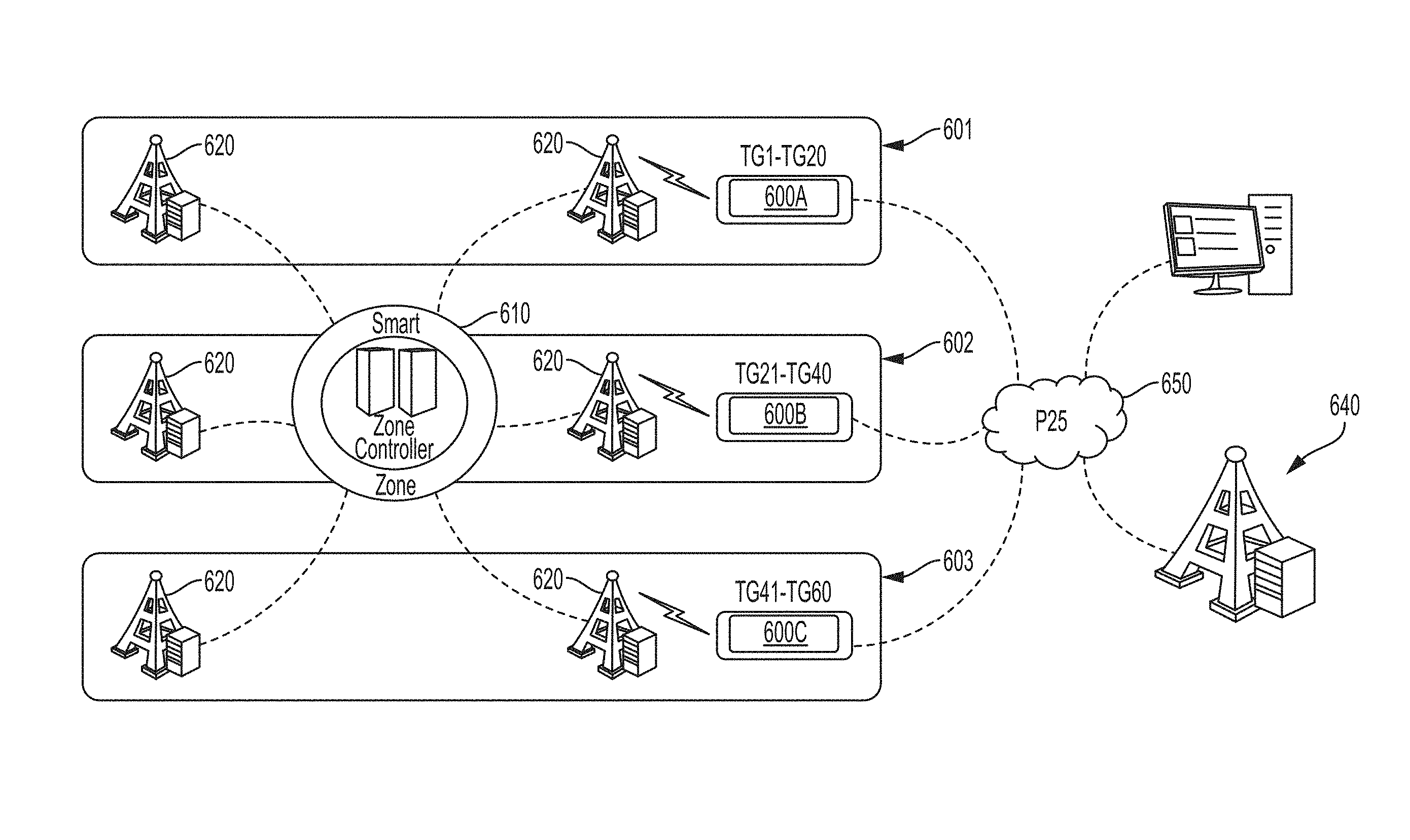
<figref idref="DRAWINGS">FIG. 6</figref> illustrates an example embodiment wherein the interoperability gateway is implemented to provide interoperability between a trunking LMR system and a P25 LMR system; and
<figref idref="DRAWINGS">FIG. 7</figref> illustrates an example flow diagram of a method for providing backup connection between a dispatch center and a Land Mobile Radio (LMR) system when the dispatch center is disconnected from the LMR system.
DETAILED DESCRIPTION
In the following detailed description and the attached drawings, numerous specific details are set forth to provide a thorough understanding of the present disclosure. However, those skilled in the art will appreciate that the present disclosure may be practiced, in some instances, without such specific details. In other instances, well-known elements have been illustrated in schematic or block diagram form in order not to obscure the present disclosure in unnecessary detail. Additionally, for the most part, specific details, and the like, have been omitted inasmuch as such details are not considered necessary to obtain a complete understanding of the present disclosure, and are considered to be within the understanding of persons of ordinary skill in the relevant art.
It is further noted that, unless indicated otherwise, all functions described herein may be performed in hardware or as software instructions for enabling a computer, radio or other device to perform predetermined operations, where the software instructions are embodied on a computer readable storage medium, such as RAM, a hard drive, flash memory or other type of computer readable storage medium known to a person of ordinary skill in the art. In certain embodiments, the predetermined operations of the computer, radio or other device are performed by a processor such as a computer or an electronic data processor in accordance with code such as computer program code, software, firmware, and, in some embodiments, integrated circuitry that is coded to perform such functions. Furthermore, it should be understood that various operations described herein as being performed by a user may be operations manually performed by the user, or may be automated processes performed either with or without instruction provided by the user.
The present disclosure provides an interoperability gateway system and method capable of providing functionality for communicating between LMR systems. For example, the interoperability gateway may convert a voice type or call type from one LMR system to a voice type or call type suitable for another LMR system, wherein the LMR systems may be of same types or different types. Examples of such LMR system types may include EF Johnson's ATLAS® P25 system, other P25 systems, conventional LMR systems, trunking LMR systems, hybrid LMR systems, wide area systems such as simulcast LMR systems and multicast LMR systems, and other LMR systems.
In some embodiments, the interoperability gateway system and method provides backup dispatch console functionality between a dispatch center and an LMR system in the event the dispatch center is disconnected from the LMR system. In general, this may be accomplished by providing an RF link between the disconnected site and the interoperability gateway via a controller, or interoperability site network interface (ISNI), that is activated when the dispatch center is disconnected from the LMR system. As discussed in greater detail below, the interoperability gateway provides the backup connection by allocating a control station for each channel (rather than for each TalkGroup) available at the disconnected LMR system. When compared to conventional dispatch console backup schemes, the disclosed interoperability gateway system and method greatly reduces the equipment needed to provide dispatch console backup, thereby decreasing equipment and operation costs, and simplifying operation by providing a solution that is virtually transparent to the dispatcher.
<figref idref="DRAWINGS">FIG. 2</figref> illustrates an example embodiment wherein the disclosed interoperability gateway <b>200</b> is hosted at various dispatch centers <b>210</b> connected via an Internet Protocol (IP) network <b>215</b> to an LMR system <b>220</b> having one or more LMR sites <b>225</b>. The dispatch centers <b>210</b> maintain a wired connection to the LMR system <b>220</b> through the IP network <b>215</b>. Radios <b>235</b> communicate at the LMR site <b>225</b> over RF connections <b>240</b>, and calls are passed to the dispatch centers <b>210</b> over the IP network <b>215</b>.
Each dispatch center <b>210</b> further includes one or more dispatch consoles <b>230</b>, which are connected to the local interoperability gateway <b>200</b>. Dispatchers conduct call operations from the consoles <b>230</b>, which include organizing calls using the TalkGroups assigned to users of the LMR system <b>220</b>. Specifically, the dispatchers originate or receive calls on particular TalkGroups configured on the dispatch console <b>230</b> and via the IP network <b>215</b>. The calls on the Talkgroups are placed on the LMR system <b>220</b> through an assignment of an RF channel to communicate with the LMR site <b>225</b> over RF connection <b>240</b>. While the dispatchers may communicate on hundreds of TalkGroups, one call can be placed through a channel at a time, thereby limiting the number of simultaneous calls that can be placed on LMR system <b>220</b>.
In the configuration illustrated in <figref idref="DRAWINGS">FIG. 2</figref>, the LMR system <b>220</b> is fully operational and the dispatch centers <b>210</b> are connected to the system <b>220</b> via the IP network <b>215</b>. As such, the interoperability gateway <b>200</b> is inactive because it is not transmitting or processing any calls. However, although inactive, the interoperability gateway <b>200</b> may still receive calls transmitted from the system <b>220</b> through both control stations and a wired connection through the IP network <b>215</b>.
Referring now to <figref idref="DRAWINGS">FIG. 3</figref>, when a connection failure <b>300</b> occurs between a dispatch center <b>210</b>A and the LMR system <b>220</b>, the interoperability gateway <b>200</b>A at the disconnected dispatch center <b>210</b>A detects the disconnection and becomes active to establish an RF connection <b>310</b> between the disconnected dispatch center <b>210</b>A and the LMR system <b>220</b>. At this point, the dispatchers operating the consoles <b>230</b>A cannot access the LMR system <b>220</b> through the wired IP network connection <b>215</b>. Nevertheless, the dispatchers are able to reuse the same TalkGroups present on their console <b>230</b>A at the time the connection failed, to seamlessly transition to communication with the LMR system <b>220</b> through the interoperability gateway <b>200</b>A. Activation of the interoperability gateway <b>200</b>A is automatic, and the dispatchers continue to use their TalkGroup resources that they were using during the wired connection through IP network <b>215</b>. As such, the switching from the wired connection to the wireless connection provided by the interoperability gateway <b>200</b>A occurs seamlessly without dispatcher intervention or interruption.
As explained in greater detail below, any calls originated from the LMR system <b>220</b> are received by the interoperability gateway <b>200</b>A via the RF connection <b>310</b>, and are passed to the consoles <b>230</b>A at the dispatch center <b>210</b>A. Conversely, any calls that originate from the dispatch center <b>210</b>A are sent via the interoperability gateway <b>200</b>A over the RF connection <b>310</b> to be placed on the LMR system <b>220</b>. Thus, the interoperability gateway <b>200</b>A provides a virtually transparent solution, because it facilitates the continued communication with the LMR system <b>220</b> via the TalkGroups displayed on the consoles <b>230</b>A with little or no interruption to the dispatcher.
It should be appreciated that, in some embodiments, the equipment comprising the interoperability gateway <b>200</b> may not be housed entirely, or in part, at the dispatch center <b>210</b>, but may instead be separated and disposed at locations in the LMR system that are separate and apart from the dispatch console <b>210</b>. It should also be appreciated that, in some embodiments, the interoperability gateway <b>200</b> may incorporate a distributed LMR architecture, such as that disclosed in U.S. patent application Ser. No. 14/217,150, entitled “Distributed Simulcast Architecture” and incorporated herein by reference for all purposes, wherein the interoperability gateway <b>200</b> operates as an LMR site <b>225</b> in the LMR system <b>220</b>.
Operation of the disclosed interoperability gateway backup console functionality is now described with reference to <figref idref="DRAWINGS">FIG. 4</figref>. <figref idref="DRAWINGS">FIG. 4</figref> illustrates an example embodiment wherein the interoperability gateway <b>400</b> is implemented in the backup console mode of operation to provide a connection <b>405</b> between a dispatch center <b>410</b> and an LMR system <b>420</b> (also referred to herein as the “connected LMR system”) when the dispatch center <b>410</b> loses its wired connection to the LMR system <b>420</b>. In some embodiments, the interoperability gateway <b>400</b> may include a router to provide IP connectivity, one or more gateway controllers <b>450</b> to provide call control, a set of control stations <b>425</b> to provide RF connection to the LMR system <b>420</b>, and one or more power supplies to provide power. In some embodiments, the interoperability gateway <b>400</b> may include additional control stations <b>425</b> and/or controllers <b>450</b> to provide redundancy in case of equipment failure.
In the example embodiment illustrated in <figref idref="DRAWINGS">FIG. 4</figref>, the LMR system <b>420</b> is a twelve-channel simulcast LMR system capable of supporting hundreds of TalkGroups while utilizing one control channel and up to eleven voice channels at a given moment to service radios <b>415</b> communicating with one or more LMR sites <b>430</b>. Accordingly, the interoperability gateway <b>400</b> is configured to mirror the functionality of the LMR system <b>420</b> by utilizing up to twelve control stations <b>425</b>, each designated to mirror one of the channels (control or voice) supported by the simulcast LMR system <b>420</b>. In some embodiments, one control station <b>425</b> monitors a control channel supported by the LMR system <b>420</b>, while each of the remaining control stations <b>425</b> are dedicated to one of the voice channels. For example, as shown in <figref idref="DRAWINGS">FIG. 4</figref>, control station <b>425</b>A may be dedicated as the control channel, and each of the remaining control stations <b>425</b> are dedicated to one of the voice channels. In some embodiments, all control stations <b>425</b> may monitor the control channel, and the assignment of a control station <b>425</b> to an RF channel may be directed via the gateway controller <b>450</b>.
The interoperability gateway <b>400</b> includes an interoperability site network interface (ISNI) <b>450</b> (also referred to herein as controller or gateway controller) that is connected to the control stations <b>425</b> over an IP network <b>440</b>. The controller <b>450</b> controls operation of the interoperability gateway <b>400</b> by performing various functions including, but not limited to, monitoring the wired connection between the dispatch center <b>410</b> and LMR system <b>420</b>, automatically activating the interoperability gateway <b>400</b> when the dispatch center <b>410</b> is disconnected from the LMR system <b>420</b>, processing calls placed on and received via the control stations <b>425</b>, managing connectivity of the control stations <b>425</b>, and providing an interface between the interoperability gateway <b>400</b> and the consoles <b>435</b> in the dispatch center <b>410</b>. In some embodiments, operation of the interoperability gateway <b>400</b> also includes deactivating the interoperability gateway <b>400</b> in the event the dispatch center <b>410</b> is reconnected with the LMR system <b>420</b> via the wired connection.
Upon failure of the wired connection between the dispatch center <b>410</b> and the LMR system <b>420</b>, the controller <b>450</b> activates the interoperability gateway <b>400</b> and utilizes the control stations <b>425</b> to establish an RF connection <b>405</b> between the dispatch center <b>410</b> and the LMR system <b>420</b>. When a call is originated from the LMR system <b>420</b> on a voice channel, the call is received by the corresponding control station <b>425</b>, which forwards the call over the IP network <b>440</b> to the controller <b>450</b>, which then passes the call to the console <b>435</b>. When a call is originated from a console <b>435</b>, the call is received by the controller <b>450</b>, and the call is placed on the LMR system <b>420</b> using a transmit control station <b>425</b>. The transmit control station <b>425</b> is a control station <b>425</b> that is assigned a voice channel and is configured to the voice channel to transmit the call to the LMR system <b>420</b>. In some embodiments, the control station <b>425</b> previously assigned to the voice channel of the LMR system <b>420</b> is then reconfigured to become the transmit control station <b>425</b> to accommodate a call from the console <b>435</b> on that same voice channel.
As discussed above, the interoperability gateway <b>400</b> provides the backup console functionality by allocating a control station <b>425</b> for each channel available at the disconnected LMR system <b>420</b>, rather than allocating a control station for each TalkGroup. When compared to conventional dispatch console backup schemes, which allocate control stations for each TalkGroup, the disclosed interoperability gateway system greatly reduces the equipment needed to provide dispatch console backup, thereby decreasing equipment and operation costs, and simplifying operation by providing a solution that is virtually transparent to the dispatcher.
In some embodiments, the disclosed interoperability gateway is capable of providing functionality for communicating between different LMR systems. For example, the interoperability gateway may convert a voice type or call type from one LMR system to a voice type or call type suitable for a different LMR system. <figref idref="DRAWINGS">FIGS. 5 and 6</figref> illustrate example embodiments of various implementations of the disclosed interoperability gateway to provide communication between various LMR systems.
<figref idref="DRAWINGS">FIG. 5</figref> illustrates an example embodiment wherein the interoperability gateway <b>500</b> is implemented to provide interoperability between a single trunking LMR site <b>520</b> and a P25 LMR system <b>540</b>. The interoperability gateway <b>500</b> includes control stations <b>525</b> connected to one or more controllers <b>530</b> via an IP network <b>535</b>. The single trunking LMR site <b>520</b> is an eight-channel trunking LMR system <b>520</b> capable of supporting many TalkGroups while utilizing one control channel and up to seven voice channels at a given moment to service radios <b>515</b> communicating with the trunking LMR site <b>520</b>. The P25 LMR system <b>540</b> may include one or more LMR sites <b>545</b> providing communication between one or more radios <b>544</b>. In the embodiment illustrated in <figref idref="DRAWINGS">FIG. 5</figref>, an additional controller <b>530</b> is implemented to provide redundancy.
The interoperability gateway <b>500</b> is configured to mirror the functionality of the trunking LMR site <b>520</b> by utilizing up to eight control stations <b>525</b>, each designed to mirror one of the channels supported by the trunking LMR site <b>520</b>. In some embodiments, one control station <b>525</b> monitors a control channel supported by the trunking LMR site <b>520</b>, while each of the remaining control stations <b>525</b> are dedicated to one of the voice channels. In some embodiments, the control stations <b>525</b> may be dynamically assigned to a channel by the controller <b>530</b>. Accordingly, the interoperability gateway <b>500</b> mirrors the trunking LMR site <b>520</b> by allocating a control station <b>525</b> to each of the channels supported by the trunking LMR site <b>520</b>.
The interoperability gateway <b>500</b> provides interoperability between the trunking LMR site <b>520</b> and the P25 LMR system <b>540</b> by processing calls between the trunking LMR site <b>520</b> and the P25 LMR system <b>540</b>. The interoperability gateway <b>500</b> establishes an RF connection <b>550</b> between the trunking LMR site <b>520</b> and the interoperability gateway <b>500</b>. When a call is originated from the trunking LMR site <b>520</b> on a voice channel, the call is received by the corresponding control station <b>525</b>, which forwards the call over the IP network <b>535</b> to the controller <b>530</b>, which converts the call to P25 protocol and connects the call with the P25 LMR system <b>540</b>. In some embodiments, the call may be sent from the controller <b>530</b> to the console <b>560</b>, and then directed to the P25 LMR system <b>540</b>. When a call is originated from the P25 LMR system <b>540</b>, the call is received by the controller <b>530</b>, and the call is placed on the trunking LMR site <b>520</b> using a transmit control station <b>525</b>. The transmit control station <b>525</b> is assigned a voice channel and is configured to the voice channel to transmit the P25 call to the trunking LMR site <b>520</b>. In some embodiments, the previously assigned control station <b>525</b> for the voice channel is then reconfigured to become the transmit control station <b>525</b>.
<figref idref="DRAWINGS">FIG. 6</figref> illustrates an example embodiment wherein one or more interoperability gateways <b>600</b> are implemented to provide interoperability between a plurality of trunking LMR sites <b>620</b> and a P25 LMR system <b>640</b>, wherein the trunking LMR sites <b>620</b> are connected through a controller <b>610</b> in a multicast configuration. In the embodiment illustrated in <figref idref="DRAWINGS">FIG. 6</figref>, a call can be setup on a particular site <b>620</b>, or it can be placed as a wide area call spanning multiple sites <b>620</b>. Additionally, TalkGroups may be restricted or zoned to particular sites <b>620</b> based on system settings. For example, in the embodiment illustrated in <figref idref="DRAWINGS">FIG. 6</figref>, a first group <b>601</b> of sites <b>620</b> communicate using a first subset of TalkGroups, a second group <b>602</b> of sites <b>620</b> communicate using a second subset of TalkGroups, and a third group <b>603</b> of sites <b>620</b> communicate using a third subset of TalkGroups.
In the embodiment illustrated in <figref idref="DRAWINGS">FIG. 6</figref>, the interoperability gateways <b>600</b> connect the plurality of LMR sites <b>620</b> to the P25 LMR system <b>640</b> via IP network <b>650</b>. Specifically, each interoperability gateway <b>600</b> provides interoperability between a particular group of TalkGroups via the sites <b>620</b> and the P25 LMR system <b>640</b>. For example, interoperability between each of the sites <b>620</b> in the first group <b>601</b> and the P25 LMR system <b>640</b> is provided by a first interoperability gateway <b>600</b>A. Similarly, interoperability between each of the sites <b>620</b> in the second group <b>602</b> and the P25 LMR system <b>640</b> is provided by a second interoperability gateway <b>600</b>B, and interoperability between each of the sites <b>620</b> in the third group <b>603</b> and the P25 LMR system <b>640</b> is provided by a third interoperability gateway <b>600</b>C. Each of the interoperability gateways <b>600</b> provide interoperability on the subset of TalkGroups assigned to the interoperability gateway's respective group of sites <b>620</b>, and each of the interoperability gateways <b>600</b> connects via an RF link to a particular LMR site <b>620</b> within the respective gateway's group of sites <b>620</b>.
In the example embodiment illustrated in <figref idref="DRAWINGS">FIG. 6</figref>, each gateway <b>600</b> is mapped to the channels of a particular group of sites <b>620</b>. However, by restricting each gateway <b>600</b> to provide communication on a set of channels, the channel resources used for a set of TalkGroups can be reduced. Calls that are not required or intended for one group of sites <b>620</b> is not placed on the interoperability gateway <b>600</b> corresponding to the unintended group of sites <b>620</b>. Thus, the channel resources for the unintended group of sites <b>620</b> are not utilized and remain available.
In the embodiment illustrated in <figref idref="DRAWINGS">FIG. 6</figref>, each interoperability gateway <b>600</b> is flexible and can be strategically located at multiple sites within the multicast system based on certain data such as existing fleet map and user activities. In some embodiments, a dummy LMR site may be created to serve as a gateway site to link all TalkGroups within the multicast system through an interoperability gateway <b>600</b>. Because the interoperability gateway <b>600</b> is located on the dummy site, there is no need for additional RF equipment, such as an antenna system, to allow the dummy site to connect to the interoperability gateway <b>600</b>. The interoperability gateway control stations can access the dummy site over an RF connection in a local environment without the need for expensive antenna, Multicoupler, and combiner equipment.
Referring now to <figref idref="DRAWINGS">FIG. 7</figref>, an example flow diagram <b>700</b> is provided illustrating a method in accordance with the disclosed system for providing backup connection between a dispatch center and a Land Mobile Radio (LMR) system when the dispatch center is disconnected from the LMR system. At block <b>701</b>, a controller detects the disconnection between the dispatch center and the LMR system. At block <b>702</b>, a communication link between the dispatch center and the disconnected LMR system is established by one or more of the control stations. At block <b>703</b>, the controller allocates a first one of the control stations as a control channel for the disconnected LMR system in response to detecting the disconnection between the dispatch center and the LMR system. At block <b>704</b>, the controller allocates a second one of the control stations as a voice channel for communicating with the disconnected LMR system over the voice channel.
In accordance with one or more embodiments, the disclosed interoperability gateway may support a unique set of TalkGroups (interoperability TalkGroups). Thus, a call on a TalkGroup may not be attempted through multiple LMR sites or through multiple controllers.
In some embodiments, TalkGroup IDs may be maintained across LMR systems connected by the disclosed interoperability gateway. Each interoperability TalkGroup ID on a connected LMR system may be mapped to a corresponding P25 TalkGroup ID on the P25 LMR system. This allows users to maintain their existing TalkGroup ID on the connected LMR system while creating new TalkGroups on the P25 system, thereby allowing mapping a connected LMR system TalkGroup to the same ID on the P25 TalkGroup.
Dynamic user IDs may be configured, in some embodiments, to indicate if the user is a radio user or a dispatcher. In some embodiments, when a call is placed originating from the P25 LMR system, the P25 LMR system user ID may be used even though the call may be placed through the control station. Conversely, when a call is placed originating from a connected LMR system, the user ID from the connected LMR system may be used. In some embodiments, when a console originated call is placed on the P25 LMR system, the interoperability gateway may place the call on the P25 LMR system as a console originated call to enable console preemption and parallel console functionality.
In some embodiments, the interoperability gateway may allow using a fixed user ID to place calls between a P25 LMR system and a connected LMR system. In such embodiments, when a P25 originated call is placed on the connected LMR system, the call is placed through the control station and the user ID of the control station or a dummy user ID is used. When a call is originated from the connected LMR system and placed on the P25 LMR system, a dummy P25 user ID may be used. A fixed user configuration may be useful, for example, when it is not possible to enter the P25 user IDs into the connected LMR system.
In some embodiments, each interoperability P25 TalkGroup configured in the interoperability gateway can be configured as confirmed or unconfirmed. If the TalkGroup is configured as confirmed, then, for calls originated from the connected LMR system, the interoperability gateway will wait for a successful response from all interested P25 sites before setting up the call. If the TalkGroup is configured as unconfirmed, then, for calls originated from the connected LMR system, the interoperability gateway will not wait for successful responses from all interested P25 sites before setting up the call.
In some embodiments, if the interoperability gateway receives a call originated from the connected LMR system, and identifies the corresponding TalkGroup as an unconfirmed TalkGroup, the interoperability gateway sends a proceed message to all interested P25 sites, and sends the voice stream without waiting for a call response from the interested sites. If the interoperability gateway receives a call originated from the connected LMR system, and identifies the corresponding TalkGroup as a confirmed TalkGroup, the interoperability gateway sends the call request to all interested P25 sites, and waits for a successful response from each site before setting up the call. Once a successful response is received from all interested P25 sites, the interoperability gateway sends a proceed message followed by the voice stream. In some embodiments, during the call setup period, the controller may queue up any voice data received from the connected LMR system to ensure voice integrity.
In some embodiments, a console originated call may be treated as a radio call originated from the connected LMR system. However, the user ID will indicate to the interoperability gateway that the call is originated from a dispatcher. In some embodiments, the interoperability gateway will proxy as a regular, dispatch console and setup the call on the P25 LMR system as a console originated call enabling additional features such as, for example, parallel console, console preemption, and console priority. Regarding the parallel console feature, a console originated call from a trunking LMR system will appear to the regular dispatch console users as a parallel console originated call. Regarding the console preemption feature, LMR system console originated calls will appear to the P25 LMR sites as a regular console originated call which will preempt any radio user call on the same TalkGroup on the P25 LMR system. Regarding the console priority feature, a LMR system console originated call will appear to the P25 LMR sites as a regular console originated call. As such, if the call gets queued, it will have higher priority in the queue over a radio originated call.
In some embodiments, when the interoperability gateway receives a call originated from a P25 LMR site on a confirmed TalkGroup, the interoperability gateway sends the call request to the connected LMR site through a control station. Once it receives a channel grant from the connected LMR site, the interoperability gateway sends a response to the originating P25 LMR site to complete the call setup. When the interoperability gateway receives a call originated from a P25 LMR site on an unconfirmed TalkGroup, the interoperability gateway receives the proceed message and sets up the call on the connected LMR system through a control station. Because the call is setup as unconfirmed, the P25 LMR site user may start transmitting the voice packets before the call is setup on the connected LMR system.
In some embodiments, if a P25 LMR system originated call is queued in the connected LMR system, the interoperability gateway may send a queue response to the P25 LMR site indicating the call is queued. When the call is granted in the connected LMR system, the interoperability gateway sends the successful call response to the P25 LMR system, which triggers the originating P25 LMR site to complete the call setup.
In some embodiments, if a P25 LMR system originated call is queued in the P25 LMR system, the call will already be setup in the connected LMR system while it is still queued in the P25 LMR site. When the call setup is completed in the P25 LMR system, the P25 voice data is sent to the connected LMR system.
In some embodiments, a console originated call may be setup as a radio originated call on the connected LMR system. The dispatch user ID may indicate to the connected LMR system that the call is originated by the console and, if the connected LMR system can support priority based on user ID, the console originated call may be given higher priority in the connected LMR system.
In some embodiments, the disclosed system may accommodate an emergency call, wherein the call request and voice stream from either the connected LMR system or the P25 LMR system indicates if a call is originated as an emergency call. In some embodiments, an emergency call originated on the connected LMR system will be setup as an emergency call on the P25 LMR system, and vice versa.
In some embodiments, the disclosed system may accommodate an emergency preemption, which allows a system to terminate an ongoing regular call on a TalkGroup to setup an emergency call on that TalkGroup.
In some embodiments, the disclosed system may accommodate an emergency alarm, which allows a subscriber unit to send an emergency indication over a control channel without using a voice resource. The emergency alarm is forwarded to all dispatch console positions monitoring the TalkGroup. In one embodiment, when a P25 LMR system user sends an emergency alarm, the P25 LMR site sends the emergency alarm to the interoperability gateway. If the interoperability gateway is configured for the TalkGroup, it will send the emergency alarm to the connected LMR system through a control station. The user ID of the originating P25 user may be used to send the emergency alarm. In some embodiments, the emergency alarm may be received by the Gold elite console through the connected LMR system.
In some embodiments the disclosed system may accommodate an end-to-end encryption scheme, which allows encrypted voice packets originated from the LMR system to be transmitted to the P25 system without decryption of such voice packets. The encrypted voice packets originated from the P25 system may be transmitted on the LMR system without decrypting the encrypted packets. This provides an end-to-end encryption function of LMR system.
In some embodiments an encrypted call from one system can be decrypted and re-encrypted by the interoperability gateway to provide different encryption schemes in the two systems. This allows each system to maintain its own voice security scheme while allowing end-to-end encryption.
In some embodiments, an encrypted call on one system can be decrypted by the interoperability gateway and placed on the other system as clear (non-encrypted) call. This may be useful in scenarios where encryption is required in one system and is either not required or not possible in the other system.
In some embodiments, the disclosed system may provide dynamic deployment of dispatch consoles with full access to all system TalkGroups, while the existing consoles remain active. For example, a mobile command vehicle or temporary dispatch center may be deployed in the event of large gatherings or crises.
In some embodiments, the disclosed system may provide seamless roaming by radios between P25 LMR systems without the use of direct wired connections between the LMR system infrastructures. This may be a backup or alternative to the P25 Inter Sub System Interface (ISSI) capability specified in P25 standards, which defines seamless radio roaming between P25 trunking systems.
In some embodiments, the disclosed system may provide data functionality between P25 LMR systems, users, and the dispatch equipment without the use of direct wired connections with LMR system infrastructures. This may be a backup connection for data solution or data solution between LMR system and console and related equipment deployed in a mobile command vehicle or center.
A number of additional and alternative embodiments of the disclosed system and method may be provided without departing from the spirit or scope of the present disclosure as set forth in the aspects provided herein. These various embodiments are believed to be understood by one of ordinary skill in the art in view of the present disclosure.
Contents6
8 sheets
Sheet 1 Sheet 2 Sheet 3 Sheet 4 Sheet 5 Sheet 6 Sheet 7 Sheet 8
Every citation, both waysCites: the store holds 309 of 310
| Document | Relation | Office | Cited during |
|---|---|---|---|
| US10461846B2 | Cited by | United States of America | Applicant |
| US11936466B2 | Cited by | United States of America | Applicant |
| US10791566B2 | Cited by | United States of America | Applicant |
| US10749737B2 | Cited by | United States of America | Applicant |
| US11496212B2 | Cited by | United States of America | Applicant |
| US10880000B2 | Cited by | United States of America | Applicant |
| US10548025B2 | Cited by | United States of America | Applicant |
| DE10061550A1 | Cites | Germany | Applicant |
| DE10104926A1 | Cites | Germany | Applicant |
| DE102007008196A1 | Cites | Germany | Applicant |
| EP1317158A1 | Cites | European Patent Office (EPO) | Applicant |
| EP1335617A1 | Cites | European Patent Office (EPO) | Applicant |
| EP1534032A1 | Cites | European Patent Office (EPO) | Applicant |
| EP1534033A1 | Cites | European Patent Office (EPO) | Applicant |
| US2001010689A1 | Cites | United States of America | Applicant |
| US2002114302A1 | Cites | United States of America | Applicant |
| US2002155839A1 | Cites | United States of America | Applicant |
| US2003016834A1 | Cites | United States of America | Applicant |
| US2003058858A1 | Cites | United States of America | Applicant |
| US2003063569A1 | Cites | United States of America | Applicant |
| US2003086405A1 | Cites | United States of America | Applicant |
| US2003095510A1 | Cites | United States of America | Applicant |
| US2004070515A1 | Cites | United States of America | Applicant |
| US2004132453A1 | Cites | United States of America | Applicant |
| US2004170149A1 | Cites | United States of America | Applicant |
| US2004214577A1 | Cites | United States of America | Applicant |
| US2004214583A1 | Cites | United States of America | Applicant |
| WO2005006798A1 | Cites | World Intellectual Property Organization (WIPO) | Applicant |
| US2005165919A1 | Cites | United States of America | Applicant |
| US2005174986A1 | Cites | United States of America | Applicant |
| US2005180448A1 | Cites | United States of America | Applicant |
| US2005198359A1 | Cites | United States of America | Applicant |
| US2005233751A1 | Cites | United States of America | Applicant |
| US2005267928A1 | Cites | United States of America | Applicant |
| US2005281208A1 | Cites | United States of America | Applicant |
| US2005282590A1 | Cites | United States of America | Applicant |
| US2006140125A1 | Cites | United States of America | Applicant |
| US2006160562A1 | Cites | United States of America | Applicant |
| US2006205398A1 | Cites | United States of America | Applicant |
| US2006211443A1 | Cites | United States of America | Applicant |
| US2006217120A1 | Cites | United States of America | Applicant |
| US2006217122A1 | Cites | United States of America | Applicant |
| US2006240814A1 | Cites | United States of America | Applicant |
| US2006262800A1 | Cites | United States of America | Applicant |
| US2006274659A1 | Cites | United States of America | Applicant |
| US2006282247A1 | Cites | United States of America | Applicant |
| US2007014263A1 | Cites | United States of America | Applicant |
| US2007019769A1 | Cites | United States of America | Applicant |
| WO2007060808A1 | Cites | World Intellectual Property Organization (WIPO) | Applicant |
| US2007061442A1 | Cites | United States of America | Applicant |
| US2007072619A1 | Cites | United States of America | Applicant |
| WO2007078467A2 | Cites | World Intellectual Property Organization (WIPO) | Applicant |
| US2007104121A1 | Cites | United States of America | Applicant |
| WO2007136270A1 | Cites | World Intellectual Property Organization (WIPO) | Applicant |
| US2007147296A1 | Cites | United States of America | Applicant |
| US2007147357A1 | Cites | United States of America | Applicant |
| US2007160181A1 | Cites | United States of America | Applicant |
| US2007242670A1 | Cites | United States of America | Applicant |
| US2007259692A1 | Cites | United States of America | Applicant |
| US2007263597A1 | Cites | United States of America | Applicant |
| US2007263798A1 | Cites | United States of America | Applicant |
| US2007293159A1 | Cites | United States of America | Applicant |
| WO2008014818A1 | Cites | World Intellectual Property Organization (WIPO) | Applicant |
| US2008056466A1 | Cites | United States of America | Applicant |
| WO2008064706A1 | Cites | World Intellectual Property Organization (WIPO) | Applicant |
| US2008076425A1 | Cites | United States of America | Applicant |
| US2008114239A1 | Cites | United States of America | Applicant |
| US2008123650A1 | Cites | United States of America | Applicant |
| US2008144644A1 | Cites | United States of America | Applicant |
| WO2008151464A1 | Cites | World Intellectual Property Organization (WIPO) | Applicant |
| US2008161006A1 | Cites | United States of America | Applicant |
| US2008270098A1 | Cites | United States of America | Applicant |
| US2008293402A1 | Cites | United States of America | Applicant |
| US2009024845A1 | Cites | United States of America | Applicant |
| US2009028059A1 | Cites | United States of America | Applicant |
| US2009052339A1 | Cites | United States of America | Applicant |
| WO2009069507A1 | Cites | World Intellectual Property Organization (WIPO) | Applicant |
| US2009112569A1 | Cites | United States of America | Applicant |
| US2009140949A1 | Cites | United States of America | Applicant |
| US2009175209A1 | Cites | United States of America | Applicant |
| US2009185502A1 | Cites | United States of America | Applicant |
| US2009254330A1 | Cites | United States of America | Applicant |
| US2009305709A1 | Cites | United States of America | Applicant |
| US2010020735A1 | Cites | United States of America | Applicant |
| US2010035619A1 | Cites | United States of America | Applicant |
| US2010105399A1 | Cites | United States of America | Applicant |
| US2010141565A1 | Cites | United States of America | Applicant |
| US2010162036A1 | Cites | United States of America | Applicant |
| US2010169446A1 | Cites | United States of America | Applicant |
| US2010178925A1 | Cites | United States of America | Applicant |
| US2010227583A1 | Cites | United States of America | Applicant |
| US2010232299A1 | Cites | United States of America | Applicant |
| US2010303033A1 | Cites | United States of America | Applicant |
| US2011034170A1 | Cites | United States of America | Applicant |
| US2012002588A1 | Cites | United States of America | Applicant |
| US2012035904A1 | Cites | United States of America | Applicant |
| US2012039201A1 | Cites | United States of America | Search report |
| US2012083307A1 | Cites | United States of America | Applicant |
| US2012102097A1 | Cites | United States of America | Applicant |
| US2012331289A1 | Cites | United States of America | Applicant |
10 priority claims, no other members on record
Priority claims10
| Document | Office | Kind | Date |
|---|---|---|---|
| 201462032376 | United States of America | P | |
| 201462032376 | United States of America | P | |
| 201514815095 | United States of America | A | |
| 201514815095 | United States of America | A | |
| 201715786476 | United States of America | A | |
| 14815095 | – | – | – |
| 62032376 | – | – | – |
| US201462032376P | – | – | – |
| US201514815095 | – | – | – |
| US201715786476 | – | – | – |
49 transactions on the USPTO file
Allowed after 1 non-final rejection.
- Non-final rejections
- 1
- Final rejections
- 0
- RCEs
- 0
- Appeals
- 0
Over time
Point at a mark for the transactionTransactions
| Event | Code | |
|---|---|---|
| Electronic ReviewELC_RVW | ELC_RVW | |
| Email NotificationEML_NTF | EML_NTF | |
| Mail Notice of AllowanceAllowedMN/=. | MN/=. | |
| Notice of Allowance Data Verification CompletedAllowedN/=. | N/=. | |
| Reasons for AllowanceEX.R | EX.R | |
| Examiner's Amendment CommunicationEX.A | EX.A | |
| Interview Summary - Examiner Initiated - TelephonicEXET | EXET | |
| Paralegal or electronic terminal disclaimer approvedP574 | P574 | |
| Terminal Disclaimer FiledDIST | DIST | |
| Information Disclosure Statement consideredIDSC | IDSC | |
| Information Disclosure Statement (IDS) FiledM844 | M844 | |
| Information Disclosure Statement (IDS) FiledWIDS | WIDS | |
| Date Forwarded to ExaminerFWDX | FWDX | |
| Response after Non-Final ActionA... | A... | |
| Request for Extension of Time - GrantedXT/G | XT/G | |
| Email NotificationEML_NTR | EML_NTR | |
| Letter Accepting Correction of Inventorship Under Rule 1.48R48ACLT | R48ACLT | |
| Filing Receipt - UpdatedFLRCPT.U | FLRCPT.U | |
| Mail Post CardPST_CRD | PST_CRD | |
| Email NotificationEML_NTF | EML_NTF | |
| Mail Non-Final RejectionNon-final rejectionMCTNF | MCTNF | |
| Email NotificationEML_NTR | EML_NTR | |
| PG-Pub Issue NotificationPG-ISSUE | PG-ISSUE | |
| Non-Final RejectionNon-final rejectionCTNF | CTNF | |
| Information Disclosure Statement consideredIDSC | IDSC | |
| Information Disclosure Statement (IDS) FiledWIDS | WIDS | |
| Information Disclosure Statement (IDS) FiledM844 | M844 | |
| Case Docketed to Examiner in GAUDOCK | DOCK | |
| Miscellaneous Incoming LetterLET. | LET. | |
| Case Docketed to Examiner in GAUDOCK | DOCK | |
| Case Docketed to Examiner in GAUDOCK | DOCK | |
| Email NotificationEML_NTR | EML_NTR | |
| Application ready for PDX access by participating foreign officesCCRDY | CCRDY | |
| Application Is Now CompleteCOMP | COMP | |
| Application Is Now CompleteCOMP | COMP | |
| Filing ReceiptFLRCPT.O | FLRCPT.O | |
| Application Dispatched from OIPEOIPE | OIPE | |
| FITF set to YES - revise initial settingFTFS | FTFS | |
| Cleared by L&R (LARS)L128 | L128 | |
| Information Disclosure Statement consideredIDSC | IDSC | |
| Information Disclosure Statement (IDS) FiledM844 | M844 | |
| Information Disclosure Statement (IDS) FiledWIDS | WIDS | |
| Referred to Level 2 (LARS) by OIPE CSRL198 | L198 | |
| Patent Term Adjustment - Ready for ExaminationPTA.RFE | PTA.RFE | |
| PTO/SB/69-Authorize EPO Access to Search ResultsSREXR141 | SREXR141 | |
| Applicants have given acceptable permission for participating foreignAPPERMS | APPERMS | |
| IFW Scan & PACR Auto Security ReviewSCAN | SCAN | |
| Entity status set to undiscounted (initial default setting or status change)BIG. | BIG. | |
| Initial Exam Team nnIEXX | IEXX |
5 legal events, as the office reported them to INPADOC
Over the term
Point at a mark for the eventEvents
| Event | Code | |
|---|---|---|
| Maintenance fee paymentMAFP | MAFP | |
| Information on status: patent grantGrantedSTCF | STCF | |
| Information on status: patent grantGrantedSTCF | STCF | |
| AssignmentAS | AS | |
| Fee payment procedureFEPP | FEPP |
Numbers
- Publication
- 10212026
- Publication, DOCDB
- 10212026
- Publication, EPODOC
- US10212026
- Application
- 15786476
- Application, DOCDB
- 201715786476
- Application, EPODOC
- US201715786476
Titles
- English
- Interoperability gateway for land mobile radio system
Patent term adjustment
- Applicant delay
- −135 days
- Net adjustment
- 0 days
Classification
- CPC, 4
- H04L41/0668
- H04W24/04
- H04L43/0811
- H04L45/28
- IPC, 5
- H04L12 24
- H04L12 703
- H04L12 26
- H04W24 04
- H04L45 28
- USPC, 1
- 370252000