Methods and apparatus for determining the status of a device
Summary by NHIP
RFID Heartbeat Status Monitoring
The method instructs an RFID device to transmit heartbeat packets containing a unique Electronic Product Code and timestamp. These packets include encrypted authentication information and may utilize a syslog format for validation by the network device.
Claim Score by NHIP
Abstract
Methods and devices are provided for determining the status of a networked device, e.g., a networked RFID device. In some embodiments of the invention, a customized packet is used to transmit a “heartbeat” from each of a plurality of networked devices to a server. Some such embodiments use a customized syslog packet for the heartbeats. The heartbeat includes identification information regarding the device, e.g., the unique electronic product code (“EPC”) of the device. The identification information may include other identification and/or authentication information, such as a shared secret and time data, which may be hashed with the identification information. The heartbeat may include information indicating the health, accuracy and/or reliability of the device and/or of the network that includes the device.
Term
Projected expiry 27 December 2028.
- Priority
- Filed
- Granted
- Today
- Projected expiry
48 claims: 5 independent, 43 dependent
- 1A method, comprising:instructing by a network device a first radio frequency identification (“RFID”) device to transmit heartbeat packets, wherein instructing by the network device is performed by sending one or more commands including provisioning information to the first RFID device, wherein the provisioning information specifies a frequency of the heartbeat packets that the first RFID device is to transmit, each of the heartbeat packets a first Electronic Product Code (“EPC”) of the first RFID device and a time stamp, wherein the EPC of the first RFID device indicates that the first RFID device transmitted the heartbeat packet and the time stamp indicates a time that the heartbeat packet was transmitted by the first RFID device, wherein the one or more commands further indicate a first time at which the first RFID device is to transmit a first one of the heartbeat packets;and determining by the network device whether the first RFID device transmitted the first one of the heartbeat packets;wherein sending one or more commands comprises sending one or more command packets including the provisioning information to the first RFID device;wherein the network device does not transmit the heartbeat packets.
- 22An apparatus, comprising:a processor;and a memory, at least one of the processor or the memory being configured for: instructing by the apparatus a first one of a plurality of radio frequency identification (RFID) devices 1 through N to transmit syslog packets by sending one or more command packets to the first one of the RFID devices, the one or more command packets specifying a first time at which the first RFID device is to transmit a first syslog packet and a first frequency at which the first RFID device is to transmit the syslog packets, the first syslog packet comprising a first Electronic Product Code (“EPC”) of the first RFID device and a first time stamp;and instructing by the apparatus each remaining RFID device of the plurality of RFID devices to transmit syslog packets, respectively, by sending additional command packets to remaining ones of the plurality of RFID devices, the additional command packets specifying second through Nth times at which at which the second through Nth RFID devices are to transmit first syslog packets, the first syslog packets including an EPC of the corresponding remaining RFID device, wherein the additional command packets specify a second frequency at which the second RFID device is to transmit the syslog packets and specify an Nth frequency at which the Nth RFID device is to transmit the syslog packets;wherein the apparatus does not transmit the syslog packets.
- 24A method, comprising:providing by a network device a first RFID device with first instructions that the first RFID device transmit first syslog packets according to a first time designation, each of the first syslog packets comprising a first Electronic Product Code (“EPC”) of the first RFID device and each of the first syslog packets being transmitted according to the first time designation specified in the first instructions, wherein the first time designation includes a first frequency with which the first RFID device is to transmit the first syslog packets;wherein providing the first RFID device with first instructions comprises transmitting a first set of one or more command packets to the first RFID device, the first set of one or more command packets including the first instructions, wherein the first instructions specify the first time designation including the first frequency with which the first RFID device is to transmit the first syslog packets;wherein the network device does not transmit the first syslog packets.
- 28A computer program embodied in a machine-readable medium, the computer program including instructions that, when executed, causes a processor to perform the following steps:instructing by a network device a first radio frequency identification (“RFID”) device to transmit heartbeat packets, wherein instructing by the network device is performed by sending one or more commands including provisioning information to the first RFID device, wherein the provisioning information specifies a frequency of the heartbeat packets that the first RFID device is to transmit, each of the heartbeat packets including a first Electronic Product Code (“EPC”) of the first RFID device and a time stamp, wherein the EPC of the first RFID device indicates that the first RFID device transmitted the heartbeat packet and the time stamp indicates a time that the heartbeat packet was transmitted by the first RFID device, wherein the one or more commands further indicate a first time at which the first RFID device is to transmit a first one of the heartbeat packets, wherein sending one or more commands comprises sending one or more command packets including the provisioning information to the first RFID device;obtaining information from content of the heartbeat packets that are received from the first RFID device;and determining whether to modify the frequency of heartbeat packets transmitted by the first RFID device;wherein the network device does not transmit the heartbeat packets.
- 44Broadest claimClaim Score 54, average(NHIP)An apparatus, comprising:a processor;and a memory, at least one of the processor or the memory being configured for: sending instructions to a first radio frequency identification (“RFID”) device, the instructions including provisioning information that specifies a type and frequency of heartbeat packets that the first RFID device is to transmit, wherein the type provided in the provisioning information indicates that the first RFID device is to transmit heartbeat packets that include a first Electronic Product Code (“EPC”) of the first RFID device and a first time stamp, wherein the EPC of the first device indicates that the first device transmitted the corresponding heartbeat packet and the first time stamp indicates a time that the corresponding heartbeat packet was transmitted by the first device;and determining whether the first RFID device is transmitting the heartbeat packets;wherein sending instructions comprises sending a command packet including the provisioning information to the first RFID device;wherein the apparatus does not transmit the heartbeat packets.
Independent claims5
114 paragraphs in 5 sections, as filed
CROSS REFERENCE TO RELATED APPLICATION
This application claims priority to the U.S. Provisional Application No. 60/570,999, entitled “Methods and Devices for Uniquely Provisioning RFID Devices” and filed on May 13, 2004. This application is related to the following U.S. patent applications, all of which are hereby incorporated by reference for all purposes: U.S. patent application Ser. No. 10/866,506, entitled “Methods and Devices for Uniquely Provisioning RFID Devices” and filed on Jun. 9, 2004; U.S. patent application Ser. No. 10/866,507, entitled “Methods and Devices for Locating and Uniquely Provisioning RFID Devices” and filed on Jun. 9, 2004; and U.S. patent application Ser. No. 10/866,285, entitled “Methods and Devices for Assigning RFID Device Personality” and filed on Jun. 9, 2004.
BACKGROUND OF THE INVENTION
1. Field of the Invention
The present invention relates methods and devices for monitoring the status of networked devices. More particularly, the present invention relates to monitoring the status of relatively unsophisticated devices, such as radio frequency identification (“RFID”) devices, in a network.
2. Description of the Related Art
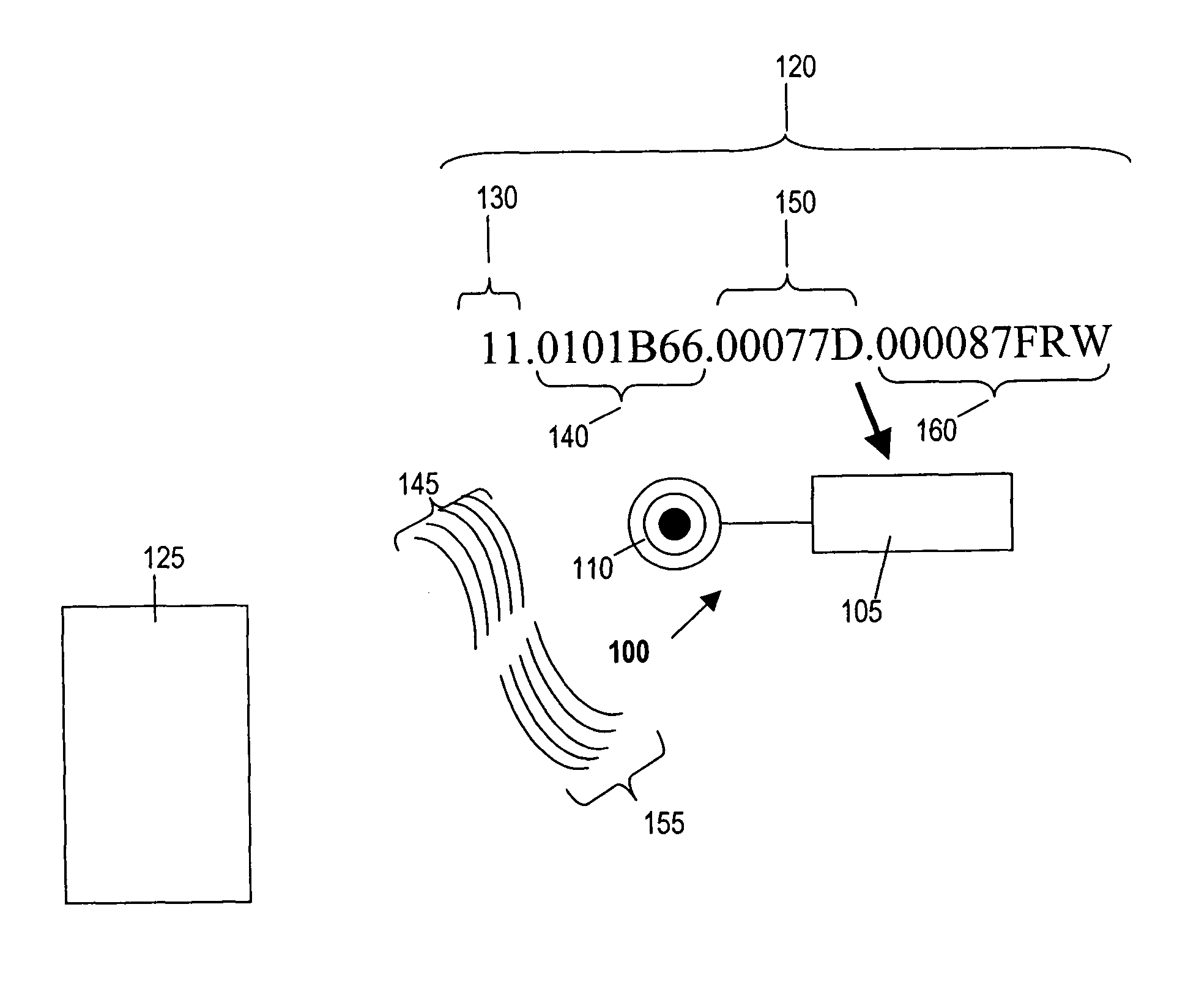
“Smart labels,” generally implemented by RFID tags, have been developed in an effort to address the shortcomings of bar codes and add greater functionality. RFID tags have been used to keep track of items such as airline baggage, items of clothing in a retail environment, cows and highway tolls. As shown in <figref idrefs="DRAWINGS">FIG. 1</figref>, an RFID tag <b>100</b> includes microprocessor <b>105</b> and antenna <b>110</b>. In this example, RFID tag <b>100</b> is powered by a magnetic field <b>145</b> generated by an RFID reader <b>125</b>. The tag's antenna <b>110</b> picks up the magnetic signal <b>145</b>. RFID tag <b>100</b> modulates the signal <b>145</b> according to information coded in the tag and transmits the modulated signal <b>155</b> to the RFID reader <b>125</b>.
RFID tags use the Electronic Product Code (“EPC” or “ePC”) format for encoding information. An EPC code includes variable length bits of information (common formats are 64, 96 and 128 bits), which allows for identification of individual products as well as associated information. As shown in <figref idrefs="DRAWINGS">FIG. 1</figref>, EPC <b>120</b> includes header <b>130</b>, EPC Manager field <b>140</b>, Object class field <b>150</b> and serial number field <b>160</b>. EPC Manager field <b>140</b> contains manufacturer information. Object class field <b>150</b> includes a product's stock-keeping unit (“SKU”) number. Serial number field <b>160</b> is a 40-bit field that can uniquely identify the specific instance of an individual product i.e., not just a make or model, but also down to a specific “serial number” of a make and model.
In theory, RFID tags and associated RFID devices (such as RFID readers and printers) could form part of a network for tracking a product (or a group of products) and its history. However, various difficulties have prevented this theory from being realized. One problem that has required considerable time and energy from RF engineers is the development of lower-cost RFID tags with acceptable performance levels.
In part because of the significant efforts that have been expended in solving the foregoing problems, prior art systems and methods for networking RFID devices are rather primitive. RFID devices have only recently been deployed with network interfaces. Prior art RFID devices and systems are not suitable for large-scale deployment of networks of RFID devices.
Conventional RFID devices also have a small amount of available memory. A typical RFID device may have approximately 0.5 Mb of flash memory and a total of 1 Mb of overall memory. The small memories of RFID devices place restrictions on the range of possible solutions to the problems noted herein. In addition, an RFID device typically uses a proprietary operating system, e.g., of the manufacturer of the microprocessor(s) used in the RFID device.
RFID devices do not currently achieve reliability levels required of customers. Moreover, many RFID devices are deployed in a hostile industrial environment (such as a warehouse or factory) by relatively unskilled “IT” personnel. RFID devices may be used intermittently or infrequently. However, when an RFID device is needed it must perform immediately or significant delays may ensue. These delays may affect an entire supply chain and could result in significant costs.
One established method of determining the status of networked devices is actively polling each device. In part because of the bandwidth consumed by the polling process, this is not a desirable method for networks involving large numbers of devices.
Therefore, it would be desirable to provide methods for ensuring that specific RFID devices, or similarly unsophisticated devices in a network, are healthy and operational. Moreover, it would be desirable to implement such methods without having to actively “poll” such devices.
SUMMARY OF THE INVENTION
Methods and devices are provided for determining the status of a networked device, e.g., a networked RFID device. In some embodiments of the invention, a customized packet is used to transmit a “heartbeat” from each of a plurality of networked devices to a server. Some such embodiments use a customized syslog packet for the heartbeats. The heartbeat includes identification information regarding the device, e.g., the unique electronic product code (“EPC”) of the device. The identification information may include other identification and/or authentication information, such as a shared secret and time data, which may be hashed with the identification information. The heartbeat may include information indicating the health, accuracy and/or reliability of the device and/or of the network that includes the device.
Some aspects of the invention provide a method for determining the status of a device. The method includes the following steps: instructing a first radio frequency identification (“RFID”) device to transmit a first packet at a first time, the first packet comprising a first Electronic Product Code (“EPC”) of the first RFID device and a first time stamp; and determining whether the first RFID device transmitted the first packet.
The first packet may be a syslog packet and may include encrypted authentication information. If so, the method can involve validating the first packet according to the authentication information. The first packet may also include information regarding the utilization of the first RFID device, Internet Protocol packet statistics, information specific to the first RFID device (e.g., information regarding a radio frequency interface of the first RFID device), information specified by a vendor of the first RFID device and/or information regarding a local area network that includes the first RFID device.
The method may also include these steps: instructing the first RFID device to transmit a second packet at a second time, the second packet comprising the first EPC and a second time stamp; and determining whether the first RFID device transmitted the second packet. The method could include the step of instructing the first RFID device to transmit a third packet at a third time, the third packet comprising the first EPC and a third time stamp, wherein a first time interval between the first time and the second time is different from a second time interval between the second time and the third time.
The method can include these steps: instructing a second RFID device to transmit a second packet at a second time, the second packet comprising an EPC of the second RFID device and a second time stamp; and determining whether the second RFID device transmitted the second packet. The second time may be different from the first time.
The second packet may include second information, in addition to the second time stamp, that is different from first information in the first packet.
Alternative aspects of the invention provide a method of determining the status of a plurality of RFID devices. The method includes the following steps: instructing a first RFID device to transmit a first syslog packet at a first time, the first syslog packet comprising a first EPC of the first RFID device and a first time stamp; instructing each of RFID devices <b>2</b> through N to transmit second through Nth syslog packets at second through Nth times, respectively, the second syslog packet comprising a second EPC of the second RFID device and a second time stamp and the Nth syslog packet comprising an Nth EPC of the Nth RFID device and an Nth time stamp.
Other aspects of the invention provide a method of determining the status of RFID devices. The method involves providing a first RFID device with first instructions to transmit first syslog packets, each of the first syslog packets comprising a first Electronic Product Code (“EPC”) of the first RFID device and each of the first syslog packets being transmitted according to a first time designation. The first time designation may include transmitting one of the first syslog packets, waiting for a first time interval to elapse, then transmitting another of the first syslog packets.
The method may also include providing the first RFID device with second instructions to transmit the first syslog packets, each of the first syslog packets comprising a first EPC of the first RFID device and each of the first syslog packets being transmitted according to a second time designation. The method could include providing the first RFID device with second instructions to transmit second syslog packets, each of the second syslog packets comprising a first EPC of the first RFID device and information not included in the first syslog packets.
Some embodiments of the invention include a computer program embodied in a machine-readable medium. The computer program contains instructions for controlling networked devices to perform the following steps: instructing a first radio frequency identification (“RFID”) device to transmit a first packet at a first time, the first packet comprising a first Electronic Product Code (“EPC”) of the first RFID device and a first time stamp; and determining whether the first RFID device transmitted the first packet.
The first packet may be a syslog packet and may include encrypted authentication information. The computer program may include instructions for validating the first packet according to the authentication information. The first packet may contain information regarding the utilization of the first RFID device, information regarding a local area network that includes the first RFID device, information regarding Internet Protocol packet statistics, information specific to the first RFID device (e.g., information regarding a radio frequency interface of the first RFID device) and/or information specified by a vendor of the first RFID device.
The computer program may also include instructions for controlling the networked devices to perform the following steps: instructing the first RFID device to transmit a second packet at a second time, the second packet comprising the first EPC and a second time stamp; and determining whether the first RFID device transmitted the second packet.
The computer program may also include commands for the following: instructing a second RFID device to transmit a second packet at a second time, the second packet comprising an EPC of the second RFID device and a second time stamp; and determining whether the second RFID device transmitted the second packet.
The second packet may include second information, in addition to the second time stamp, that is different from first information in the first packet.
The computer program may include instructions for causing the first RFID device to transmit a third packet at a third time, the third packet comprising the first EPC and a third time stamp, wherein a first time interval between the first time and the second time is different from a second time interval between the second time and the third time.
Alternative implementations of the invention include a method for implementing an RFID network The method includes these steps: positioning a networked RFID reader at an exit door of a retail store; enabling the RFID reader to read RFID tags passing through the exit door and to transmit RFID tag information to an RFID network; instructing the RFID reader to transmit a first syslog packet at a first time, the first packet comprising a first EPC of the RFID reader, a first time stamp and a secret; and determining that the RFID reader transmitted the first syslog packet, thereby determining that the RFID reader is operational.
The RFID tag information can include product information and/or shopper information. The method may also include the step of using the RFID tag information to automatically update a database maintained by the retail store and/or a database maintained by a manufacturer of at least one of the products. The method can include the step of using the RFID tag information to cause a financial account to be debited for a cost of the products.
The method can include the step of using the RFID tag information to update a business plan. The business plan may be a marketing plan, a manufacturing plan, a distribution plan and/or a sales plan.
BRIEF DESCRIPTION OF THE DRAWINGS
<figref idrefs="DRAWINGS">FIG. 1</figref> is a diagram illustrating an RFID tag.
<figref idrefs="DRAWINGS">FIG. 2</figref> illustrates an exemplary RFID network according to the present invention.
<figref idrefs="DRAWINGS">FIG. 3</figref> is a flow chart that outlines a method according to the present invention.
<figref idrefs="DRAWINGS">FIG. 4</figref> illustrates one exemplary format of a heartbeat packet of the present invention.
<figref idrefs="DRAWINGS">FIG. 5</figref> is a block diagram of an exemplary RFID reader that may be configured to perform some methods of the present invention.
<figref idrefs="DRAWINGS">FIG. 6</figref> is a block diagram of an exemplary RFID printer that may be configured to perform some methods of the present invention.
<figref idrefs="DRAWINGS">FIG. 7</figref> is a block diagram of an exemplary RFID system that may be configured to perform some methods of the present invention.
<figref idrefs="DRAWINGS">FIG. 8</figref> is a flow chart that provides an overview of some implementations of the present invention.
<figref idrefs="DRAWINGS">FIG. 9</figref> illustrates an example of a network device that may be configured to implement some methods of the present invention.
DETAILED DESCRIPTION OF THE INVENTION
In this application, numerous specific details are set forth in order to provide a thorough understanding of the present invention. It will be obvious, however, to one skilled in the art, that the present invention may be practiced without some or all of these specific details. In other instances, well known process steps have not been described in detail in order not to obscure the present invention.
The present invention involves methods and apparatus for determining the status of devices in a network. Most of the discussion will involve networked RFID devices. However, those of skill in the art will realize that many aspects of the present invention can be applied to determining the status of other types of devices in a network, particularly devices that are relatively unsophisticated. For example, the methods and devices of the present invention are suitable for networked industrial devices and to sensor networks. Similarly, although much of the discussion herein applies to implementations using customized packets that are generally within the syslog protocol as described in RFC 3164 (hereby incorporated by reference in its entirety), the present invention is not protocol-specific.
Without modification, the syslog protocol is not suitable for implementing the present invention. One basic problem is described in Section 6.2 of RFC 3164: <ul><li id="ul0001-0001" num="0000"><ul><li id="ul0002-0001" num="0043">The syslog delivery mechanism does not strongly associate the message with the message sender. The receiver of that packet will not be able to ascertain that the message was indeed sent from the reported sender, or if the packet was sent from another device.</li></ul></li></ul>
Section 6.2.2, entitled “Message Forgery,” warns that this aspect of syslog has been exploited by attackers: <ul><li id="ul0003-0001" num="0000"><ul><li id="ul0004-0001" num="0045">Malicious exploits of this behavior have also been noted. An attacker may transmit syslog messages (either from the machine from which the messages are purportedly sent or from any other machine) to a collector. In one case, an attacker may hide the true nature of an attack amidst many other messages. As an example, an attacker may start generating forged messages indicating a problem on some machine. This may get the attention of the system administrators who will spend their time investigating the alleged problem. During this time, the attacker may be able to compromise a different machine, or a different process on the same machine. Additionally, an attacker may generate false syslog messages to give untrue indications of status or of events. As an example, an attacker may stop a critical process on a machine, which may generate a notification of exit. The attacker may subsequently generate a forged notification that the process had been restarted. The system administrators may accept that misinformation and not verify that the process had indeed been restarted.</li></ul></li></ul>
Moreover, Section 6.6, “Message Observation,” contains the following admonitions: <ul><li id="ul0005-0001" num="0000"><ul><li id="ul0006-0001" num="0047">Neither the syslog protocol nor the syslog application have mechanisms to provide confidentiality of the messages in transit. In most cases passing clear-text messages is a benefit to the operations staff if they are sniffing the packets off of the wire. The operations staff may be able to read the messages and associate them with other events seen from other packets crossing the wire to track down and correct problems. Unfortunately, an attacker may also be able to observe the human-readable contents of syslog messages. The attacker may then use the knowledge gained from those messages to compromise a machine or do other damage.</li></ul></li></ul>
Nonetheless, in some embodiments of the invention, a customized packet generally within the syslog protocol is used to transmit a “heartbeat” from each of a plurality of networked devices to a syslog server. In order to overcome the problems noted above, the heartbeat includes identification information regarding the device, e.g., the unique electronic product code (“EPC”) of the device. The packet preferably includes other identification and/or authentication information, such as a shared secret and time data, which may be hashed with the identification information. The heartbeat may include information indicating the health, accuracy and/or reliability of the device and/or of the network that includes the device.
The methods and devices of the present invention have very broad utility, both in the public and private sectors. Any enterprise needs to keep track of how its equipment is being deployed, whether that equipment is used for commercial purposes, for military purposes, etc. RFID devices, sensors, etc., that are networked according to the present invention can provide necessary information for allowing enterprises to track equipment and products (or groups of products). The information that will be provided by devices that are networked according to the present invention will be of great benefit for enterprise resource planning, including the planning of manufacturing, distribution, sales and marketing.
For example, using the devices and methods of the present invention, RFID tags and associated RFID devices (such as RFID readers and printers) can form part of a network for tracking a product and its history. Instead of waiting in a checkout line to purchase selected products, a shopper who wishes to purchase products bearing RFID tags can, for example, transport the products through a door that has an RFID reader nearby. The EPC information regarding the products can be provided to an RFID network by the reader and can be used to automatically update a store inventory, cause a financial account to be debited, update manufacturers', distributors' and retailers' product sales databases, etc.
Read/write RFID tags can capture information regarding the history of products or groups of products, e.g., temperature and other environmental changes, stresses, accelerations and/or vibrations that have acted upon the product. It will be particularly useful to record such information for products that relatively more subject to spoilage or other damage, such as perishable foods and fragile items. By using the methods of the present invention, this information will be used to update databases maintained by various entities (e.g., manufacturers, wholesalers, retailers, transportation companies and financial institutions). The information will be used not only to resolve disputes (for example, regarding responsibility for product damage) but also to increase customer satisfaction, to avoid health risks, etc.
Some aspects of the invention use a combination of EPC code information and modified versions of existing networking standards for determining the status of devices, such as RFID readers and RFID printers, that are located in a network. An example of such a network is depicted in <figref idrefs="DRAWINGS">FIG. 2</figref>. Here, RFID network <b>200</b> includes warehouse <b>201</b>, factory <b>205</b>, retail outlet <b>210</b>, financial institution <b>215</b> and headquarters <b>220</b>. As will be appreciated by those of skill in the art, network <b>200</b> could include many other elements and/or multiple instances of the elements shown in <figref idrefs="DRAWINGS">FIG. 2</figref>. For example, network <b>200</b> could include a plurality of warehouses, factories, etc., and may include a very large number of RFID devices.
In this illustration, products <b>227</b> are being delivered to warehouse <b>201</b> by truck <b>275</b>. Products <b>227</b>, which already include RFID tags, are delivered through door <b>225</b>. In this example, RFID reader <b>252</b> is connected to port <b>262</b> of switch <b>260</b>. Here, switches <b>230</b> and <b>260</b> are connected to the rest of RFID network <b>200</b> via gateway <b>250</b> and network <b>225</b>. Network <b>225</b> could be any convenient network, but in this example network <b>225</b> is the Internet. RFID reader <b>252</b> reads each product that passes through door <b>225</b> and transmits the EPC code corresponding to each product on RFID network <b>200</b>.
RFID tags may be used for different levels of a product distribution system. For example, there may be an RFID tag for a pallet of cases, an RFID tag for each case in the pallet and an RFID tag for each product. Accordingly, after products <b>227</b> enter warehouse <b>201</b>, they are assembled into cases <b>246</b>. RFID printer <b>256</b> makes an RFID tag for each of cases <b>246</b>. In this example, RFID printer <b>256</b> is connected to port <b>266</b> of switch <b>260</b>. RFID printer <b>256</b> could operate under the control of PC <b>247</b> in warehouse <b>201</b>, one of PCs <b>267</b> in headquarters <b>220</b>, or some other device.
RFID reader <b>224</b>, which is connected to port <b>214</b>, reads the EPC code of each case <b>246</b> and product <b>227</b> on conveyor belt <b>244</b> and transmits this information on network <b>200</b>. Similarly, RFID reader <b>226</b>, which is connected to port <b>216</b>, reads the EPC code of each case <b>246</b> and product <b>227</b> that exits door <b>204</b> and transmits this information on network <b>200</b>. Cases <b>246</b> are loaded onto truck <b>285</b> for distribution to another part of the product chain, e.g., to retail outlet <b>210</b>.
Each of the RFID devices in network <b>200</b> preferably has a “personality” of enabled functions that are suitable for its intended use. For example, device <b>252</b> could cause a reassuring tone to sound and/or a green light to flash if an authorized person or object enters door <b>225</b>. However, device <b>252</b> might cause an alarm to sound and/or an alert to be sent to an administrator on network <b>200</b> if a product exits door <b>225</b> or an unauthorized person enters or exits door <b>225</b>.
The functionality of the RFID devices in a network such as network <b>200</b> may be critical to the success of an enterprise. This is no less true in view of the fact that RFID devices may not be in use at all times. If one of the RFID devices described above were not operational during a time of expected use, a delay could ensue that would affect the processing and delivery of many products. For example, if RFID reader <b>252</b> were not functioning when products <b>227</b> were being delivered to warehouse <b>201</b> by truck <b>275</b>, the delivery of products <b>227</b> through door <b>225</b> may be delayed. This delay would cause a delay in the processing of products <b>227</b>, leading to a corresponding delay in the distribution of cases <b>246</b> to another part of the product chain. This delay could result in losses of revenue for several enterprises, including wholesalers, distributors and retailers.
<figref idrefs="DRAWINGS">FIG. 3</figref> is a flow chart that outlines method <b>300</b> according to some implementations of the present invention. In step <b>301</b>, a first device is instructed to transmit a first packet at a first time. The packet will sometimes be referred to herein as a “heartbeat” or a “heartbeat packet.”
The instructions are preferably provided to a device during a provisioning process, an example of which will be described below, and stored in a memory of the device for execution by the device's CPU. The provisioning methods (and other methods) described in U.S. patent application Ser. No. 10/866,285, which has been incorporated herein by reference, may advantageously be used for implementing some aspects of the present invention. In some implementations, for example, the instructions are provided to the first device as part of a provisioning or reprovisioning process via a DHCPFORCERENEW command. The command may originate from a server, a host device operated by a network administrator, etc.
In this example, the instructions call for the first device to transmit a first packet at a first time (T<sub>1</sub>) and to keep transmitting subsequent packets at a predetermined first time interval (ΔT<sub>1</sub>) until further instructions are received. The first time interval is preferably tailored to the expected usage of the first device during the time beginning at T<sub>1</sub>. For example, if the device is expected to be inactive, the first time interval is preferably a relatively longer time interval than if the first device is active or is soon expected to be active.
Preferably, the packet is a customized syslog packet that contains identification information for uniquely identifying the device. The identification information may include, e.g., the EPC code of the device. Moreover the packet preferably contains authentication information and a time stamp. The authentication information may be, for example, a secret that is assigned during the provisioning process. All or part of the packet may be encrypted. In some implementations, only the authentication information is encrypted.
The packet may contain other information, e.g., diagnostic information that may be useful for troubleshooting. Examples of customized syslog packets for implementing the present invention are described below with reference to <figref idrefs="DRAWINGS">FIG. 4</figref>.
In method <b>300</b>, a plurality of networked devices is instructed to transmit packets at different times and possibly at different time intervals. Accordingly, a second device is instructed to transmit a packet at T<sub>2</sub>, another packet at T<sub>2</sub>+ΔT<sub>2 </sub>(a predetermined second time interval), etc. (Step <b>305</b>) As with the first device, the second time interval is preferably set according to the expected usage of the second device. This procedure is applied to all N devices in a network: the N<sup>th </sup>device is instructed to transmit a packet at T<sub>N</sub>, another packet at T<sub>N</sub>+ΔT<sub>N </sub>(a predetermined N<sup>th </sup>time interval), etc. (Step <b>310</b>) In some implementations, at least some of the times and/or time intervals are “staggered” in order to minimize the number of packets that are expected to arrive (e.g., at a syslog server) during a particular time interval.
In step <b>315</b>, it is determined whether heartbeat packets have been received from devices <b>1</b> through N (e.g., by a syslog server). In some preferred embodiments, it will be determined whether each heartbeat packet has been received within a predetermined time. Preferably, the packets' receipt will be determined during an ongoing process, rather than at one particular phase of method <b>300</b>. In some implementations, received packets are archived and in other implementations received packets are discarded. In yet other implementations, certain types of heartbeat packets (e.g., those containing information about device or network status) are stored and other types of heartbeat packets are discarded. Preferably, an event timer will be reset after each packet is received.
In preferred implementations, an authentication process will be applied to at least some packets. In some implementations, the authentication process involves comparing a hashed portion of the heartbeat that includes a secret from a device with what the heartbeat server expected. The secret authorized for the device that sent the heartbeat, e.g., by referencing a database, a lookup table, etc is used by the server to generate a hash value. If the correct secret was included in the heartbeat from the device, it will be assumed that the device indicated by the identification information (e.g., an EPC code) in the heartbeat was the device that transmitted the heartbeat. The authorization process is preferably not applied to all packets. For example, an authorization process may be applied to every M packets, where M is a predetermined number (50, 100, 1,000, 10,000, or any appropriate number). Heartbeats purportedly from devices involving critical operations, valuable items, etc., may be authenticated more often than heartbeats that appear to be from other devices.
If an expected packet is not received within a predetermined time, in some implementations a notification procedure will then ensue (step <b>320</b>). For example, a communication (e.g., an email, voice mail, text message, etc.) may be sent to a network administrator regarding the non-responsive device (e.g., “No heartbeat from RFID reader <b>3313</b> at warehouse <b>111</b>”). In other implementations, a notification will be sent only after a predetermined number of expected packets have not been received from a non-responsive device. In some implementations, a non-responsive device will be instructed to reboot.
It will be appreciated by those of skill in the art that the steps of method <b>300</b> are not necessarily performed in the order indicated. For example, the Nth device may actually be provided with instructions for transmitted a packet before the first device is provided with such instructions. As noted above, the packets' receipt will preferably be determined as part of an ongoing process rather than during only one sequential step of method <b>300</b>. Moreover, the step of determining whether a change of instructions is warranted (step <b>325</b>) could occur at various times.
In step <b>325</b>, it is determined whether a change is required in the packets transmitted by any of devices <b>1</b> through N. This determination could be made in response to various factors, including the time of day, calendar (e.g. holiday versus working day), knowledge of an event that will involve a device, indications of a device's recent activity levels, etc. For example, new instructions calling for a change in heartbeat frequency could be issued in response to a determination that a particular device's activity level is about to change.
In one such example, a database accessible to an administrative device (e.g., a server, a host device, etc.) indicates that a delivery is expected at a warehouse door at 6:00 a.m. An RFID device at the warehouse door has been inactive for a number of hours because the warehouse has been closed for the night. Therefore, the RFID device has previously been instructed to transmit heartbeats at a relatively long time interval (e.g., once every hour). Because of known event and the expected change in activity of the RFID device, the administrative device transmits instructions that tell the device to increase the heartbeat frequency to, e.g., 5 minutes.
The new heartbeat instructions may be part of configuration/personality software that is transmitted to the RFID device. For example, the device may be instructed to reboot, assume a personality appropriate for that of an inbound warehouse door, change its antenna reading pattern and increase its heartbeat frequency.
A change may also be indicated by information contained in the heartbeat itself. As noted elsewhere, heartbeats may include various types of information regarding the device that transmitted the heartbeat, the network in which the device is located, or other information. If information in the heartbeat suggests, for example, that the device may be malfunctioning, the device may be instructed to provide heartbeats with other diagnostic information. Exemplary scenarios of this type are discussed below.
However, in some implementations of the invention, the device may be pre-programmed to change its heartbeat frequency and/or to change the information contained in the heartbeat. In some such implementations, the device is pre-programmed to change its heartbeat frequency and/or to change the information contained in the heartbeat at predetermined times. In alternative implementations, the device may be pre-programmed to change its heartbeat frequency and/or to change the information contained in the heartbeat if a predetermined condition occurs. For example, the device may be preprogrammed to transmit device and/or network diagnostic information if the CPU usage of the device exceeds a threshold level.
<figref idrefs="DRAWINGS">FIG. 4</figref> illustrates one exemplary heartbeat format for implementing some aspects of the invention. It will be appreciated by those of skill in the art that other formats may be used for implementing the present invention. According to RFC 3164, “[t]he payload of any IP packet that has a UDP destination port of 514 MUST be treated as a syslog message.” Accordingly, even those implementations of the invention that are based in part on syslog need not be in a particular format. Nonetheless, implementations of the present invention that use syslog are preferably formatted in the manner suggested by RFC 3164.
Therefore, the exemplary heartbeat packet <b>400</b> of <figref idrefs="DRAWINGS">FIG. 4</figref> includes the priority (“PRI”) <b>405</b>, header <b>410</b> and message <b>415</b> portions set forth in RFC 3164. However, one or more portions of heartbeat packet <b>400</b> (e.g., the message portion) are customized to implement the present invention. PRI portion <b>405</b> may be used, for example, to encode one of the 24 Facility codes and/or one of the 8 Severity codes that are set forth in RFC 3164. Header portion <b>410</b> includes a time and date stamp, along with an indication of the hostname or IP address of the device.
The remainder of heartbeat packet <b>400</b> is message portion <b>415</b>. Message portion <b>415</b> preferably begins with “TAG” portion <b>420</b>, which indicates the name of the program and/or process that generated the packet (here, “Heartbeat”). The rest of message portion <b>415</b> is the “content” portion, which includes identification information <b>425</b> and authentication information <b>430</b> in this example. Here, identification information <b>425</b> is the EPC of the device transmitting the heartbeat. In some embodiments, authentication information <b>430</b> is a secret that has previously been provided to the device during a provisioning process, e.g., as described in co-pending U.S. patent application Ser. No. 10/866,285, which has previously been incorporated by reference. The authentication information is preferably encrypted (e.g., hashed) by the device that sent the heartbeat.
One preferred method to hash the data is using an algorithm similar to MD-5. In order to ensure that illicit decryption of the packets are not done, and hence a replay or misinformation attack is done, at least one the keys making up the hash algorithm should be variable. The use of time or a sequence key are common methods. Time is used as syslog packets should contain a timestamp per RFC 3164. However this key is open in the packet and may be used in decryption attacks. A Heartbeat sequence could be used where a random number is chosen and incremented based on a predetermined integer for each heartbeat packet sent. This integer could be per device specific and random, making the sequence value difficult to determine. Further as it is not transmitted, it makes it much more difficult to reverse decrypt.
Some heartbeat packets <b>400</b> may serve only to identify the device that transmitted the heartbeat and the time that the heartbeat was transmitted. However, heartbeat packet <b>400</b> (or packets having other formats) may contain other types of information. Preferably, this information is set forth according to standardized option fields having predetermined formats. One such exemplary format is CPU_Memory_Disk Utilization. The CPU field may contain, for example, the average percent utilization of the CPU since the time that the last heartbeat was sent and The Memory and Disk Utilization fields could contain information regarding their respective utilizations.
In a second example, heartbeat packet <b>400</b> contains LAN interface and/or IP packet statistics, preferably in a predetermined format. For example, such packets could include information regarding “receiver not ready” conditions, dropped packets or frames, megaframes, wrong format of packets or frames, etc.
In a third example, heartbeat packet <b>400</b> contains device Uptime information, preferably in a predetermined format. For example, such packets include a “time since last boot” in seconds. Thus an application may determine if the Uptime has lowered from a previous heartbeat packet that the device has been rebooted or it has reset itself.
Alternatively, the heartbeat may contain information specific to a particular vendor or device. Such information could be used for error reporting, product differentiation, or other purposes. If the device is an RFID reader, the heartbeat could include information regarding the performance of the reader, e.g., the current antenna set-up, interference information, incomplete reads, percent of “good” reads, multipath information, etc.
The DHCP protocol is used in some preferred implementations of the present invention because it offers various convenient features. For example, the DHCP protocol allows pools or “scopes” of TCP/IP addresses to be defined. A DHCP server can temporarily allocate or “lease” these TCP/IP addresses to host devices. An IP address that is not used for the duration of the lease is returned to the pool of unallocated IP addresses. In addition, the DHCP server will provide all related configuration settings, such as the default router, Domain Name Service (“DNS”) servers, subnet mask, etc., that are required for the proper functioning of TCP/IP.
For implementations using the DHCP protocol, DHCP Options may be used to pass provisioning information, including instructions for the desired type and frequency of heartbeats that a device should transmit. The DHCP protocol is defined in RFC 2131 and DHCP Options are set forth in, for example, RFCs 2132, 3004 and 3046. RFCs 2131, 2132, 3004 and 3046 are hereby incorporated by reference for all purposes.
According to some implementations of the invention, a DHCP server causes an update of a device's heartbeat type or frequency (and/or other device reconfiguration) using a DHCPFORCERENEW command as defined by RFC 3203, which is hereby incorporated by reference in its entirety. In some such implementations, the CPU of the RFID device registers the DHCPFORCERENEW command and starts a new provisioning cycle, for example as described with reference to FIGS. 6 and 7 of U.S. patent application Ser. No. 10/866,285, which has been incorporated by reference in its entirety.
However, in other implementations of the invention, the device may be pre-programmed to change its heartbeat frequency and/or type at predetermined times and/or if one or more predetermined conditions occur. In yet other implementations, a device may be preprogrammed to request new instructions for heartbeat frequency and/or type at a particular time or if certain conditions occur. In some such implementations, the device does so via a DHCPREQUEST, e.g. as described in U.S. patent application Ser. No. 10/866,285.
In order to secure a command, in some implementations a cached secret is hashed within the command. For example, the secret can be included with the EPC code of the RFID device.
One method for creating an authentication key is as follows:
MD-5 (EPC, Challenge, Secret)
By adding in the variable of a random Challenge, no replay attacks of the hash code could be used. Because the EPC is included, the authentication can be further validated to come from a specific device.
<figref idrefs="DRAWINGS">FIG. 5</figref> illustrates an RFID reader that can be configured to perform methods of the present invention. RFID reader <b>500</b> includes one or more RF radios <b>505</b> for transmitting RF waves to, and receiving modulated RF waves from, RFID tags. RF radios <b>505</b> provide raw RF data that is converted by an analog-to-digital converter (not shown) and conveyed to other elements of RFID reader <b>500</b>. In some embodiments, these data are stored, at least temporarily, by CPU <b>510</b> in memory <b>515</b> before being transmitted to other parts of RFID network <b>200</b> via network interface <b>525</b>. Network interface <b>525</b> may be any convenient type of interface, such as an Ethernet interface.
Flash memory <b>520</b> is used to store a program (a “bootloader”) for booting/initializing RFID reader <b>500</b>. The bootloader, which is usually stored in a separate, partitioned area of flash memory <b>520</b>, also allows RFID reader <b>500</b> to recover from a power loss, etc. In some embodiments of the invention, flash memory <b>520</b> includes instructions for controlling CPU <b>510</b> to form heartbeats, requests to initiate a provisioning/configuration cycle, etc. In some implementations, flash memory <b>520</b> is used to store personality information and other configuration information obtained from, e.g., a DHCP server during such a cycle.
However, in preferred implementations, such information is only stored in volatile memory <b>515</b> after being received from, e.g. a DHCP server. There are advantages to keeping RFID devices “dumb.” For example, a network of dumb RFID devices allows much of the processing load to be centralized (e.g., performed by server <b>270</b> of network <b>200</b>), instead of being performed by the RFID devices. Alternatively, the processing load can be decentralized, but only to trusted devices (such as PC <b>247</b> of network <b>200</b>).
Configuration information is downloaded from, e.g., a central server to memory <b>515</b>. Updates may be instigated by the central server or selected, trusted devices. New versions of the image file (e.g., the running, base image necessary to operate the RFID device) are copied into flash memory <b>520</b>. Alternative embodiments of RFID devices implement the methods of the present invention yet lack flash memory.
Newer RFID devices also include dry contact input/output leads to connect to signal lights, industrial networks or the equivalent. These newer RFID devices typically have evolved in the amount of memory, flash, CPU capacity and methods of determination of the number, type and content of RFID tags in their field of view.
<figref idrefs="DRAWINGS">FIG. 6</figref> is a block diagram illustrating an exemplary RFID printer <b>600</b> that may be configured to perform some methods of the present invention. RFID printer <b>600</b> has many of the same components as RFID reader <b>500</b> and can be configured in the same general manner as RFID reader <b>500</b>.
RFID printer also includes printer interface <b>630</b>, which may be a standard printer interface. Printer interface prints a label for each RFID tag, e.g. according to instructions received from network <b>200</b> via network interface <b>625</b>.
RF Radio <b>605</b> is an outbound radio that is used to send RF signals to the antenna of an RFID tag under the control of CPU <b>610</b>, thereby encoding information (e.g. an EPC) on the tag's microprocessor. Preferably, RF Radio <b>605</b> then checks the encoded information for accuracy. The RFID tag is sandwiched within the label produced by printer interface <b>630</b>.
<figref idrefs="DRAWINGS">FIG. 7</figref> illustrates RFID system <b>700</b> that includes control portion <b>701</b> and RF radio portion <b>702</b>. The components of control portion <b>701</b> are substantially similar to those described above with reference to <figref idrefs="DRAWINGS">FIGS. 5 and 6</figref>. Interconnect <b>730</b> of control portion <b>701</b> is configured for communication with interconnect <b>735</b> of RF radio portion <b>702</b>. The communication may be via any convenient medium and format, such as wireless, serial, point-to-point serial, etc. Although only one RF radio portion <b>702</b> is depicted in <figref idrefs="DRAWINGS">FIG. 7</figref>, each control portion <b>701</b> may control a plurality of RF radio portions <b>702</b>. RFID system <b>700</b> may be deployed on a single framework or chassis (e.g., on a forklift) or in multiple chassis.
<figref idrefs="DRAWINGS">FIG. 8</figref> is a flow chart that illustrates an exemplary business application of the present invention. Those of skill in the art will appreciate that the example described below with reference to <figref idrefs="DRAWINGS">FIG. 8</figref> is but one of many applications of the invention.
In step <b>805</b>, an RFID device has already been provisioned with heartbeat instructions, etc., according to one or more of the previously-described methods. In this example, the RFID device is an RFID reader that is positioned near an exit door of a retail store. Therefore, in the previous steps, the device has been provisioned with a personality that is appropriate for its role.
Moreover, the device is provisioned with instructions for transmitting one or more types of heartbeats at a frequency that is appropriate for the actual or anticipated use of the device. In this example, the retail store has just opened. Therefore, in the recent past (e.g., 45 minutes ago), the device was instructed to reboot, to increase its heartbeat frequency and to transmit heartbeats with device and local network information. An administrator has determined from these heartbeats that the device is online and is functioning adequately.
In step <b>810</b>, a shopper exits the door with a number of selected products. In step <b>815</b>, the RFID reader reads the RFID tags of each product and extracts the EPC codes and related product information (e.g., the price of each product).
The RFID reader also reads an RFID tag that identifies the shopper and the shopper's preferred account(s) that should be debited in order to purchase the products. For example, the shopper may have an RFID tag embedded in a card, a key chain, or any other convenient place in which this information is encoded. The accounts may be various types of accounts maintained by one or more financial institutions. For example, the accounts may be one or more of a checking account, savings account, a line of credit, a credit card account, etc. Biometric data (e.g., voice, fingerprint, retinal scan, etc.) from the shopper may also be obtained and compared with stored biometric data in order to verify the shopper's identity.
In step <b>820</b>, the RFID reader transmits the product information, including the EPC codes, on the RFID network. In this example, the information is first sent to a financial institution indicated by the shopper's RFID tag.
In step <b>825</b>, the financial institution that maintains the shopper's selected account determines whether there are sufficient funds (or whether there is sufficient credit) for the shopper to purchase the selected products. If so, the shopper's account is debited and the transaction is consummated (step <b>830</b>).
In this example, the shopper has the option of designating one or more alternative accounts. Accordingly, if the first account has insufficient funds or credit, it is determined (e.g., by a server on the RFID network) whether there the shopper has indicated any alternative accounts for making purchases (step <b>835</b>). If so, the next account is evaluated in step <b>825</b>. If it is determined in step <b>835</b> that there are no additional accounts designated by the shopper, in this example some form of human intervention takes place. For example, a cashier of the retail store could assist the shopper in making the purchases in a conventional manner.
If some or all of the products are purchased, information regarding the purchased products (including the EPC codes) is transmitted on the RFID network. For example, this information is preferably forwarded to one or more devices on the RFID network that are configured to update one or more databases maintained by the retail store or the manufacturers/producers, distributors, wholesalers, etc., of the purchased products (step <b>840</b>). In some implementations, information regarding the shopper is also transmitted on the RFID network (e.g., if the shopper has authorized such information to be released). This product information (and optionally shopper information) may be used for a variety of purposes, e.g., in the formation of various types of business plans (e.g., inventory re-stocking, marketing, sales, distribution and manufacturing/production plans).
<figref idrefs="DRAWINGS">FIG. 9</figref> illustrates an example of a network device that may be configured to implement some methods of the present invention. For example, network device <b>960</b> may be a syslog server that is configured to implement some aspects of the invention.
Network device <b>960</b> includes a master central processing unit (CPU) <b>962</b>, interfaces <b>968</b>, and a bus <b>967</b> (e.g., a PCI bus). Generally, interfaces <b>968</b> include ports <b>969</b> appropriate for communication with the appropriate media. In some embodiments, one or more of interfaces <b>968</b> includes at least one independent processor <b>974</b> and, in some instances, volatile RAM. Independent processors <b>974</b> may be, for example ASICs or any other appropriate processors. According to some such embodiments, these independent processors <b>974</b> perform at least some of the functions of the logic described herein. In some embodiments, one or more of interfaces <b>968</b> control such communications-intensive tasks as media control and management. By providing separate processors for the communications-intensive tasks, interfaces <b>968</b> allow the master microprocessor <b>962</b> efficiently to perform other functions such as routing computations, network diagnostics, security functions, etc.
The interfaces <b>968</b> are typically provided as interface cards (sometimes referred to as “line cards”). Generally, interfaces <b>968</b> control the sending and receiving of data packets over the network and sometimes support other peripherals used with the network device <b>960</b>. Among the interfaces that may be provided are Fibre Channel (“FC”) interfaces, Ethernet interfaces, frame relay interfaces, cable interfaces, DSL interfaces, token ring interfaces, and the like. In addition, various very high-speed interfaces may be provided, such as fast Ethernet interfaces, Gigabit Ethernet interfaces, ATM interfaces, HSSI interfaces, POS interfaces, FDDI interfaces, ASI interfaces, DHEI interfaces and the like.
When acting under the control of appropriate software or firmware, in some implementations of the invention CPU <b>962</b> may be responsible for implementing specific functions associated with the functions of a desired network device. According to some embodiments, CPU <b>962</b> accomplishes all these functions under the control of software including an operating system (e.g. Linux, VxWorks, etc.), and any appropriate applications software.
CPU <b>962</b> may include one or more processors <b>963</b> such as a processor from the Motorola family of microprocessors or the MIPS family of microprocessors. In an alternative embodiment, processor <b>963</b> is specially designed hardware for controlling the operations of network device <b>960</b>. In a specific embodiment, a memory <b>961</b> (such as non-volatile RAM and/or ROM) also forms part of CPU <b>962</b>. However, there are many different ways in which memory could be coupled to the system. Memory block <b>961</b> may be used for a variety of purposes such as, for example, caching and/or storing data, programming instructions, etc.
Regardless of network device's configuration, it may employ one or more memories or memory modules (such as, for example, memory block <b>965</b>) configured to store data, program instructions for the general-purpose network operations and/or other information relating to the functionality of the techniques described herein. The program instructions may control the operation of an operating system and/or one or more applications, for example.
Because such information and program instructions may be employed to implement the systems/methods described herein, the present invention relates to machine-readable media that include program instructions, state information, etc. for performing various operations described herein. Examples of machine-readable media include, but are not limited to, magnetic media such as hard disks, floppy disks, and magnetic tape; optical media such as CD-ROM disks; magneto-optical media; and hardware devices that are specially configured to store and perform program instructions, such as read-only memory devices (ROM) and random access memory (RAM). The invention may also be embodied in a carrier wave traveling over an appropriate medium such as airwaves, optical lines, electric lines, etc. Examples of program instructions include both machine code, such as produced by a compiler, and files containing higher level code that may be executed by the computer using an interpreter.
Although the system shown in <figref idrefs="DRAWINGS">FIG. 9</figref> illustrates one specific network device of the present invention, it is by no means the only network device architecture on which the present invention can be implemented. For example, an architecture having a single processor that handles communications as well as routing computations, etc. is often used. Further, other types of interfaces and media could also be used with the network device. The communication path between interfaces/line cards may be bus based (as shown in <figref idrefs="DRAWINGS">FIG. 9</figref>) or switch fabric based (such as a cross-bar).
Other Embodiments
Although illustrative embodiments and applications of this invention are shown and described herein, many variations and modifications are possible which remain within the concept, scope, and spirit of the invention, and these variations would become clear to those of ordinary skill in the art after perusal of this application. For example, it will be appreciated by those of skill in the art that this document applies to monitoring the status of any relatively unsophisticated devices in a network, e.g., to monitoring networked sensing devices, devices in an industrial network, etc.
Accordingly, the present embodiments are to be considered as illustrative and not restrictive, and the invention is not to be limited to the details given herein, but may be modified within the scope and equivalents of the appended claims.
Contents5
10 sheets
Sheet 1 Sheet 2 Sheet 3 Sheet 4 Sheet 5 Sheet 6 Sheet 7 Sheet 8 Sheet 9 Sheet 10
Every citation, both waysCites: the store holds 114 of 115
| Document | Relation | Office | Cited during |
|---|---|---|---|
| US9064164B2 | Cited by | United States of America | Applicant |
| US2007109100A1 | Cited by | United States of America | Pre-grant |
| US8700778B2 | Cited by | United States of America | Applicant |
| WO2022269564A1 | Cited by | World Intellectual Property Organization (WIPO) | International search |
| US10972483B2 | Cited by | United States of America | Applicant |
| US12511628B2 | Cited by | United States of America | Applicant |
| US10868821B2 | Cited by | United States of America | Search report |
| US8698603B2 | Cited by | United States of America | Applicant |
| US2001012292A1 | Cites | United States of America | Search report |
| US2001028308A1 | Cites | United States of America | Applicant |
| US2002001307A1 | Cites | United States of America | Applicant |
| US2002016739A1 | Cites | United States of America | Applicant |
| US2002046263A1 | Cites | United States of America | Applicant |
| US2002075805A1 | Cites | United States of America | Applicant |
| US2002161907A1 | Cites | United States of America | Applicant |
| US2003046339A1 | Cites | United States of America | Applicant |
| US2003065784A1 | Cites | United States of America | Applicant |
| US2003095032A1 | Cites | United States of America | Applicant |
| US2003126248A1 | Cites | United States of America | Applicant |
| US2003174714A1 | Cites | United States of America | Applicant |
| US2003177374A1 | Cites | United States of America | Search report |
| US2003226887A1 | Cites | United States of America | Applicant |
| US2004010594A1 | Cites | United States of America | Applicant |
| US2004021569A1 | Cites | United States of America | Applicant |
| US2004061646A1 | Cites | United States of America | Applicant |
| US2004064577A1 | Cites | United States of America | Search report |
| US2004069852A1 | Cites | United States of America | Applicant |
| US2004073600A1 | Cites | United States of America | Applicant |
| US2004100383A1 | Cites | United States of America | Applicant |
| US2004108795A1 | Cites | United States of America | Applicant |
| US2004128389A1 | Cites | United States of America | Applicant |
| US2004145474A1 | Cites | United States of America | Applicant |
| US2004257202A1 | Cites | United States of America | Applicant |
| US2004259557A1 | Cites | United States of America | Applicant |
| US2005021626A1 | Cites | United States of America | Applicant |
| US2005027778A1 | Cites | United States of America | Applicant |
| US2005080881A1 | Cites | United States of America | Applicant |
| US2005093679A1 | Cites | United States of America | Applicant |
| US2005099270A1 | Cites | United States of America | Applicant |
| US2005102406A1 | Cites | United States of America | Applicant |
| US2005199716A1 | Cites | United States of America | Applicant |
| US2005209947A1 | Cites | United States of America | Applicant |
| US2005228887A1 | Cites | United States of America | Applicant |
| US2005252957A1 | Cites | United States of America | Applicant |
| US2005252970A1 | Cites | United States of America | Applicant |
| US2005252971A1 | Cites | United States of America | Applicant |
| US2005253717A1 | Cites | United States of America | Applicant |
| US2005253718A1 | Cites | United States of America | Applicant |
| US2005253722A1 | Cites | United States of America | Applicant |
| US2005264420A1 | Cites | United States of America | Applicant |
| US2006005035A1 | Cites | United States of America | Applicant |
| US2006010086A1 | Cites | United States of America | Applicant |
| US2006022801A1 | Cites | United States of America | Applicant |
| US2006031374A1 | Cites | United States of America | Applicant |
| US2006044111A1 | Cites | United States of America | Applicant |
| US2006091999A1 | Cites | United States of America | Applicant |
| US2006123467A1 | Cites | United States of America | Applicant |
| US2006132304A1 | Cites | United States of America | Applicant |
| US2006143318A1 | Cites | United States of America | Applicant |
| US2006146879A1 | Cites | United States of America | Applicant |
| US2006253590A1 | Cites | United States of America | Applicant |
| US2006259183A1 | Cites | United States of America | Applicant |
| US2006266832A1 | Cites | United States of America | Applicant |
| US2006280181A1 | Cites | United States of America | Applicant |
| US2007013518A1 | Cites | United States of America | Applicant |
| US2007027966A1 | Cites | United States of America | Applicant |
| US2007080784A1 | Cites | United States of America | Applicant |
| US2007109100A1 | Cites | United States of America | Search report |
| US2007112574A1 | Cites | United States of America | Applicant |
| US2007258048A1 | Cites | United States of America | Applicant |
| US2007283001A1 | Cites | United States of America | Applicant |
| US4625081A | Cites | United States of America | Search report |
| US4688026A | Cites | United States of America | Applicant |
| US5339073A | Cites | United States of America | Applicant |
| US5588009A | Cites | United States of America | Search report |
| US5646616A | Cites | United States of America | Applicant |
| US5850187A | Cites | United States of America | Applicant |
| US5887176A | Cites | United States of America | Applicant |
| US6070187A | Cites | United States of America | Applicant |
| US6111517A | Cites | United States of America | Applicant |
| US6115079A | Cites | United States of America | Applicant |
| US6212563B1 | Cites | United States of America | Applicant |
| US6272113B1 | Cites | United States of America | Search report |
| US6300903B1 | Cites | United States of America | Applicant |
| US6324575B1 | Cites | United States of America | Applicant |
| US6330597B2 | Cites | United States of America | Applicant |
| US6393458B1 | Cites | United States of America | Applicant |
| US6473858B1 | Cites | United States of America | Search report |
| US6539281B2 | Cites | United States of America | Applicant |
| US6553489B1 | Cites | United States of America | Applicant |
| US6843121B1 | Cites | United States of America | Applicant |
| US6912213B2 | Cites | United States of America | Search report |
| US6931574B1 | Cites | United States of America | Applicant |
| US6963282B1 | Cites | United States of America | Applicant |
| US7057511B2 | Cites | United States of America | Applicant |
| US7064660B2 | Cites | United States of America | Applicant |
| US7075412B1 | Cites | United States of America | Applicant |
| US7081819B2 | Cites | United States of America | Applicant |
| US7103040B2 | Cites | United States of America | Applicant |
| US7103886B2 | Cites | United States of America | Applicant |
65 members in 6 offices
Priority claims6
| Document | Office | Kind | Date |
|---|---|---|---|
| 57099904 | United States of America | P | |
| 57099904 | United States of America | P | |
| 89123804 | United States of America | A | |
| 60570999 | – | – | – |
| US20040570999P | – | – | – |
| US20040891238 | – | – | – |
Members65
| Document | Office | Kind | |
|---|---|---|---|
| US2005252957A1 | United States of America | A1 | |
| US2005252970A1 | United States of America | A1 | |
| US2005252971A1 | United States of America | A1 | |
| US2005253717A1 | United States of America | A1 | |
| US2005253718A1 | United States of America | A1 | |
| US2005253722A1 | United States of America | A1 | |
| AU2005246794A1 | Australia | A1 | |
| AU2005246794A2 | Australia | A2 | |
| CA2565099A1 | Canada | A1 | |
| CA2565451A1 | Canada | A1 | |
| CA2565456A1 | Canada | A1 | |
| US2005264420A1 | United States of America | A1 | |
| WO2005114545A2 | World Intellectual Property Organization (WIPO) | A2 | |
| WO2005114602A2 | World Intellectual Property Organization (WIPO) | A2 | |
| WO2005114603A2 | World Intellectual Property Organization (WIPO) | A2 | |
| WO2005114604A2 | World Intellectual Property Organization (WIPO) | A2 | |
| WO2005114545A8 | World Intellectual Property Organization (WIPO) | A8 | |
| WO2005114545A3 | World Intellectual Property Organization (WIPO) | A3 | |
| WO2005114603A8 | World Intellectual Property Organization (WIPO) | A8 | |
| US2006033606A1 | United States of America | A1 | |
| WO2005114602A3 | World Intellectual Property Organization (WIPO) | A3 | |
| US2006091999A1 | United States of America | A1 | |
| WO2005114603A3 | World Intellectual Property Organization (WIPO) | A3 | |
| US2006266832A1 | United States of America | A1 | |
| EP1751687A2 | European Patent Office (EPO) | A2 | |
| EP1759328A2 | European Patent Office (EPO) | A2 | |
| EP1761881A2 | European Patent Office (EPO) | A2 | |
| EP1763856A2 | European Patent Office (EPO) | A2 | |
| CN1954327A | China | A | |
| CN1954328A | China | A | |
| CN1954329A | China | A | |
| WO2005114604A3 | World Intellectual Property Organization (WIPO) | A3 | |
| US7322523B2 | United States of America | B2 | |
| US7325734B2 | United States of America | B2 | |
| WO2008016488A2 | World Intellectual Property Organization (WIPO) | A2 | |
| US7336175B2 | United States of America | B2 | |
| US2008087730A1 | United States of America | A1 | |
| WO2008016488A3 | World Intellectual Property Organization (WIPO) | A3 | |
| US2008197980A1 | United States of America | A1 | |
| US7422152B2 | United States of America | B2 | |
| CN101263506A | China | A | |
| EP2047440A2 | European Patent Office (EPO) | A2 | |
| CN100531082C | China | C | |
| CN100531083C | China | C | |
| CA2565456C | Canada | C | |
| CN100561499C | China | C | |
| US7648070B2 | United States of America | B2 | |
| US7658319B2 | United States of America | B2 | |
| AU2005246794B2 | Australia | B2 | |
| US7789308B2 | United States of America | B2 | |
| EP1751687A4 | European Patent Office (EPO) | A4 | |
| EP1759328A4 | European Patent Office (EPO) | A4 | |
| EP1761881A4 | European Patent Office (EPO) | A4 | |
| EP1763856A4 | European Patent Office (EPO) | A4 | |
| CN101263506B | China | B | |
| US8060623B2 | United States of America | B2 | |
| US2012036243A1 | United States of America | A1 | |
| US8113418B2 | United States of America | B2 | |
| US8249953B2This record | United States of America | B2 | |
| US8601143B2 | United States of America | B2 | |
| US8604910B2 | United States of America | B2 | |
| CA2565451C | Canada | C | |
| CA2565099C | Canada | C | |
| EP1763856B1 | European Patent Office (EPO) | B1 | |
| EP1759328B1 | European Patent Office (EPO) | B1 |
166 transactions on the USPTO file
Allowed after 3 non-final rejections, 3 final rejections and 3 RCEs.
- Non-final rejections
- 3
- Final rejections
- 3
- RCEs
- 3
- Appeals
- 0
Over time
Point at a mark for the transactionTransactions
| Event | Code | |
|---|---|---|
| Payment of Maintenance Fee, 12th Year, Large EntityM1553 | M1553 | |
| Email NotificationEML_NTR | EML_NTR | |
| Change in Power of Attorney (May Include Associate POA)PA.. | PA.. | |
| Correspondence Address ChangeC.AD | C.AD | |
| Payment of Maintenance Fee, 8th Year, Large EntityM1552 | M1552 | |
| Recordation of Patent Grant MailedPGM/ | PGM/ | |
| Patent Issue Date Used in PTA CalculationAllowedPTAC | PTAC | |
| Email NotificationEML_NTR | EML_NTR | |
| Issue Notification MailedAllowedWPIR | WPIR | |
| Dispatch to FDCD1935 | D1935 | |
| Application Is Considered Ready for IssuePILS | PILS | |
| Issue Fee Payment VerifiedN084 | N084 | |
| Issue Fee Payment ReceivedIFEE | IFEE | |
| Printer Rush- No mailingTCPB | TCPB | |
| Printer Rush- No mailingTCPB | TCPB | |
| Email NotificationEML_NTR | EML_NTR | |
| Filing Receipt - CorrectedFLRCPT.C | FLRCPT.C | |
| Pubs Case Remand to TCPUBTC | PUBTC | |
| Electronic ReviewELC_RVW | ELC_RVW | |
| Email NotificationEML_NTF | EML_NTF | |
| Mail Notice of AllowanceAllowedMN/=. | MN/=. | |
| Notice of Allowance Data Verification CompletedAllowedN/=. | N/=. | |
| Email NotificationEML_NTR | EML_NTR | |
| Mail Examiner Initiated Interview SummaryMEXIE | MEXIE | |
| Reasons for AllowanceEX.R | EX.R | |
| Examiner's Amendment CommunicationEX.A | EX.A | |
| Interview Summary - Examiner InitiatedEXIE | EXIE | |
| Date Forwarded to ExaminerFWDX | FWDX | |
| Disposal for a RCE / CPA / R129AbandonedABN9 | ABN9 | |
| Information Disclosure Statement consideredIDSC | IDSC | |
| Reference capture on IDSRCAP | RCAP | |
| Information Disclosure Statement (IDS) FiledM844 | M844 | |
| Request for Continued Examination (RCE)RCEX | RCEX | |
| Request for Extension of Time - GrantedXT/G | XT/G | |
| Information Disclosure Statement (IDS) FiledWIDS | WIDS | |
| Workflow - Request for RCE - BeginBRCE | BRCE | |
| Email NotificationEML_NTR | EML_NTR | |
| Mail Applicant Initiated Interview SummaryMEXIA | MEXIA | |
| Interview Summary- Applicant InitiatedEXIA | EXIA | |
| Electronic ReviewELC_RVW | ELC_RVW | |
| Email NotificationEML_NTF | EML_NTF | |
| Mail Final Rejection (PTOL - 326)Final rejectionMCTFR | MCTFR | |
| Final RejectionFinal rejectionCTFR | CTFR | |
| Date Forwarded to ExaminerFWDX | FWDX | |
| Information Disclosure Statement consideredIDSC | IDSC | |
| Reference capture on IDSRCAP | RCAP | |
| Information Disclosure Statement (IDS) FiledM844 | M844 | |
| Response after Non-Final ActionA... | A... | |
| Request for Extension of Time - GrantedXT/G | XT/G | |
| Information Disclosure Statement (IDS) FiledWIDS | WIDS | |
| Electronic ReviewELC_RVW | ELC_RVW | |
| Email NotificationEML_NTF | EML_NTF | |
| Mail Non-Final RejectionNon-final rejectionMCTNF | MCTNF | |
| Non-Final RejectionNon-final rejectionCTNF | CTNF | |
| Miscellaneous Incoming LetterLET. | LET. | |
| Email NotificationEML_NTR | EML_NTR | |
| Mail Examiner Interview Summary (PTOL - 413)MEXIN | MEXIN | |
| Date Forwarded to ExaminerFWDX | FWDX | |
| Disposal for a RCE / CPA / R129AbandonedABN9 | ABN9 | |
| Information Disclosure Statement consideredIDSC | IDSC | |
| Reference capture on IDSRCAP | RCAP | |
| Information Disclosure Statement (IDS) FiledM844 | M844 | |
| Request for Continued Examination (RCE)RCEX | RCEX | |
| Information Disclosure Statement (IDS) FiledWIDS | WIDS | |
| Workflow - Request for RCE - BeginBRCE | BRCE | |
| Examiner Interview Summary Record (PTOL - 413)EXIN | EXIN | |
| Correspondence Address ChangeC.ADB | C.ADB | |
| Electronic ReviewELC_RVW | ELC_RVW | |
| Email NotificationEML_NTF | EML_NTF | |
| Mail Final Rejection (PTOL - 326)Final rejectionMCTFR | MCTFR | |
| Final RejectionFinal rejectionCTFR | CTFR | |
| Date Forwarded to ExaminerFWDX | FWDX | |
| Information Disclosure Statement consideredIDSC | IDSC | |
| Reference capture on IDSRCAP | RCAP | |
| Information Disclosure Statement (IDS) FiledM844 | M844 | |
| Response after Non-Final ActionA... | A... | |
| Information Disclosure Statement (IDS) FiledWIDS | WIDS | |
| Electronic ReviewELC_RVW | ELC_RVW | |
| Email NotificationEML_NTF | EML_NTF | |
| Mail Non-Final RejectionNon-final rejectionMCTNF | MCTNF | |
| Non-Final RejectionNon-final rejectionCTNF | CTNF | |
| Information Disclosure Statement consideredIDSC | IDSC | |
| Reference capture on IDSRCAP | RCAP | |
| Information Disclosure Statement (IDS) FiledM844 | M844 | |
| Information Disclosure Statement (IDS) FiledWIDS | WIDS | |
| Date Forwarded to ExaminerFWDX | FWDX | |
| Disposal for a RCE / CPA / R129AbandonedABN9 | ABN9 | |
| Request for Continued Examination (RCE)RCEX | RCEX | |
| Workflow - Request for RCE - BeginBRCE | BRCE | |
| Electronic ReviewELC_RVW | ELC_RVW | |
| Email NotificationEML_NTF | EML_NTF | |
| Mail Final Rejection (PTOL - 326)Final rejectionMCTFR | MCTFR | |
| Final RejectionFinal rejectionCTFR | CTFR | |
| Date Forwarded to ExaminerFWDX | FWDX | |
| Information Disclosure Statement consideredIDSC | IDSC | |
| Reference capture on IDSRCAP | RCAP | |
| Information Disclosure Statement (IDS) FiledM844 | M844 | |
| Response after Non-Final ActionA... | A... | |
| Information Disclosure Statement (IDS) FiledWIDS | WIDS | |
| Mail Non-Final RejectionNon-final rejectionMCTNF | MCTNF |
5 legal events, as the office reported them to INPADOC
Over the term
Point at a mark for the eventEvents
| Event | Code | |
|---|---|---|
| Maintenance fee paymentMAFP | MAFP | |
| Maintenance fee paymentMAFP | MAFP | |
| Fee paymentFPAY | FPAY | |
| Information on status: patent grantGrantedPATENTED CASESTCF | STCF | |
| AssignmentAS | AS |
Numbers
- Publication
- 08249953
- Publication, DOCDB
- 8249953
- Publication, EPODOC
- US8249953
- Application
- 10891238
- Application, DOCDB
- 89123804
- Application, EPODOC
- US20040891238
Titles
- English
- Methods and apparatus for determining the status of a device
Patent term adjustment
- A delay
- +1,275 daysthe office missed an examination deadline
- B delay
- +1,025 dayspendency past three years
- Overlap
- −607 daysdelays counted once
- Applicant delay
- −65 days
- Net adjustment
- 1,628 days
Classification
- CPC, 1
- G06K17/00
- IPC, 1
- G06Q10 00
- USPC, 5
- 705028000
- 340009100
- 340010100
- 370335000
- 370445000