Automated configuration of network device ports
Summary by NHIP
Automated Port Configuration
The method automatically configures network device ports by examining DHCP options within incoming DHCPDISCOVER requests. It applies stored macros based on identified device types or vendor identifiers to establish appropriate settings without manual user intervention.
Claim Score by NHIP
Abstract
Methods and devices are provided for identifying end devices and automatically configuring associated network settings. Preferred implementations of the invention do not require users to manually identify connection types (e.g., RFID, IPphone, manufacturing device, etc.) or to manually configure the network device. Accordingly, such implementations allow automatic switch configuration, even for devices that use inconsistent protocols and/or protocols that are not well known. Some methods of the invention employ DHCP options combined with traffic snooping to identify devices and automatically apply appropriate switch port configuration.
Term
Projected expiry 3 November 2027.
- Priority
- Filed
- Granted
- Today
- Projected expiry
20 claims: 3 independent, 17 dependent
- 1Broadest claimClaim Score 73, broad(NHIP)A method for establishing network device port settings, the method comprising:receiving a DHCPDISCOVER request from a first device by a second device;examining at least one DHCP option of the DHCPDISCOVER request;determining by the second device, based on a device type or vendor identifier specified in the at least one DHCP option in the DHCPDISCOVER request, whether an appropriate macro is available to configure a port of the second device on which the DHCPDISCOVER request was received;and, if the appropriate macro is determined to be available, causing by the second device the port of the second device to be configured by applying the appropriate macro.
- 12An apparatus for establishing network device port settings, the apparatus comprising:a port for receiving a DHCPDISCOVER request form a first device;a memory;and at least one logic device configured for: examining at least one DHCP option of the DHCPDTSCOVER request determining, based on a device type or vendor identifier specified in the at least one DHCP option in the DHCPDISCOVER request, whether an appropriate macro is available to configure the port on which the DHCPDISCOVER request was received: and, if the appropriate macro is determined to be available, causing the port on which the DHCPDISCOVER request was received to be configured by applying the appropriate macro.
- 17A non-transitory computer-readable storage medium storing thereon instructions for establishing network device port settings, comprising:instructions for examining at least one DHCP option of a DHCPDISCOVER request received from a first device by a second device;instructions for determining by the second device, based on a device type or vendor identifier specified in at least one DHCP option in the DHCPDISCOVER request, whether an appropriate macro is available to configure a pod of the second device on which the DHCPDISCOVER request was received;and instructions or causing by the second device the port of the second device to be configured by applying the appropriate macro, if the appropriate macro is determined to be available.
Independent claims3
75 paragraphs in 5 sections, as filed
CROSS-REFERENCE TO RELATED APPLICATIONS
This application claims priority to U.S. Provisional Patent Application No. 60/570,999, entitled “Methods and Devices for Uniquely Provisioning RFID Devices” and filed on May 13, 2004, which is hereby incorporated by reference for all purposes. This application is related to U.S. patent application Ser. No. 10/866,506, entitled “Methods and Devices for Uniquely Provisioning RFID Devices” and filed on Jun. 9, 2004, to U.S. patent application Ser. No. 10/866,507, entitled “Methods and Devices for Locating and Uniquely Provisioning RFID Devices” and filed on Jun. 9, 2004, to U.S. patent application Ser. No. 10/866,285, entitled “Methods and Devices for Assigning RFID Device Personality” and filed on Jun. 9, 2004, to U.S. patent application Ser. No. 10/896,410, filed Jul. 21, 2004 and to U.S. patent application Ser. No. 11/010,089, entitled “Methods and Devices for Providing Scalable RFID Networks” and filed on Dec. 9, 2004 (collectively, the “Cross-Referenced Applications”), all of which are hereby incorporated by reference for all purposes.
BACKGROUND OF THE INVENTION
1. Field of the Invention
The present invention relates the configuration of devices in a network.
2. Description of the Related Art
It is becoming commonplace for devices, including but not limited to RFID readers, RFID printers, VoIP telephones and devices used in manufacturing, to be deployed in large numbers within some networks. These devices often have unique characteristics, such as traffic type, bandwidth requirements, security demands, etc. Accordingly, such devices require specific network configurations, e.g., quality of service (“QoS”), security settings, VLANs or VSANs, etc. to properly support their desired functionality.
<figref idrefs="DRAWINGS">FIG. 1</figref> illustrates a portion of a network <b>100</b>, in which network device <b>105</b> (in this example, a Catalyst™ switch provided by Cisco Systems, Inc.) is connected to a plurality of devices, including RFID reader <b>110</b>. In this example, RFID reader <b>110</b> is connected to port <b>120</b> via a fast Ethernet connection. For each port of network device <b>105</b>, a variety of attributes may be configured, such as QoS, security, port speed, description, etc.
Within network <b>100</b>, a large number of devices and associated network devices may be deployed. In general, it is a tedious and time-consuming process for users to deploy devices and to manage the associated infrastructure components, such as switches and other network devices. For example, the process of configuring switch port settings is currently a manual process, in which each desired attribute must be individually selected and enabled for a port.
This manual configuration process is currently inhibiting the deployment of large-scale RFID networks, manufacturing device networks, etc. It would be desirable to provide improved methods and devices that overcome at least some limitations of the prior art.
SUMMARY OF THE INVENTION
Methods and devices are provided for identifying end devices and automatically configuring associated network settings. Preferred implementations of the invention do not require users to manually identify connection types (e.g., RFID, IPphone, manufacturing device, etc.) or to manually configure the network device. Accordingly, such implementations allow automatic switch configuration, even for devices that use inconsistent protocols and/or protocols that are not well known.
Some methods of the invention employ DHCP options combined with traffic snooping to identify devices and automatically apply appropriate switch port configuration. Some such implementations of the invention trigger Cisco Systems' SmartPorts™ software to configure ports of network devices. Some aspects of the SmartPorts software are described in U.S. patent application Ser. No. 10/896,410, filed Jul. 21, 2004, which has been incorporated herein by reference. However, the present invention is not limited to implementation via SmartPorts™; any convenient software for the automated configuring of network device ports may be used in accordance with the present invention.
Some implementations of the invention provide a method for establishing network device port settings. The method includes the steps of receiving a DHCPDISCOVER request from a device and of determining, based on information in the DHCPDISCOVER request, whether an appropriate macro is available to configure a port of a network device on which the DHCPDISCOVER request was first received.
The method may also include the step of applying the appropriate macro when it is determined to be available. The method preferably includes the step of determining whether the port has already been configured in a manner appropriate for the device.
The determining step may involve determining a device personality, identifying the device and/or examining at least one DHCP option or other component of the DHCPDISCOVER request. The “other component” could be, for example, one or more parts of the DHCP message header. The determining step may or may not be performed by the network device on which the DHCPDISCOVER request was first received. For example, the DHCPDISCOVER request may first be received by a switch port and the determining step may be performed by one of a DHCP server, an edge services management server, an authentication server and a device dedicated to port configuration.
Some embodiments of the invention provide at least one apparatus for establishing network device port settings. Such embodiments include a port for receiving a DHCPDISCOVER request from a device and at least one logic device configured for determining, based on information in the DHCPDISCOVER request, whether an appropriate macro is available to configure the port.
A logic device may examine one or more DHCP options of the DHCPDISCOVER request. The port and the logic device(s) may be included within a single device or may be disposed in separate devices. For example, the port and the logic device(s) may be included within a single switch or a DHCP server.
Alternative embodiments of the invention provide a network device that includes these elements: a plurality of ports; a storage device; and at least one logic device configured to receive a DHCPDISCOVER request from a device via a first port and configure the first port with appropriate configuration parameters for the device.
A logic device may be further configured to forward a copy of the DHCPDISCOVER request to a second device. A logic device may configure the first port according to instructions received from the second device. The second device may be, for example, a DHCP server, an edge services management server, an authentication server or a device dedicated to port configuration.
The methods of the present invention may be implemented, at least in part, by hardware and/or software. For example, some embodiments of the invention provide computer programs embodied in machine-readable media. The computer programs include instructions for controlling one or more devices to perform the methods described herein.
BRIEF DESCRIPTION OF THE DRAWINGS
<figref idrefs="DRAWINGS">FIG. 1</figref> is a network diagram illustrating a switch and attached RFID devices.
<figref idrefs="DRAWINGS">FIG. 2A</figref> illustrates an exemplary SmartPorts™ macro.
<figref idrefs="DRAWINGS">FIG. 2B</figref> illustrates an exemplary set of commands to be used for configuring a port according to a SmartPorts™ macro.
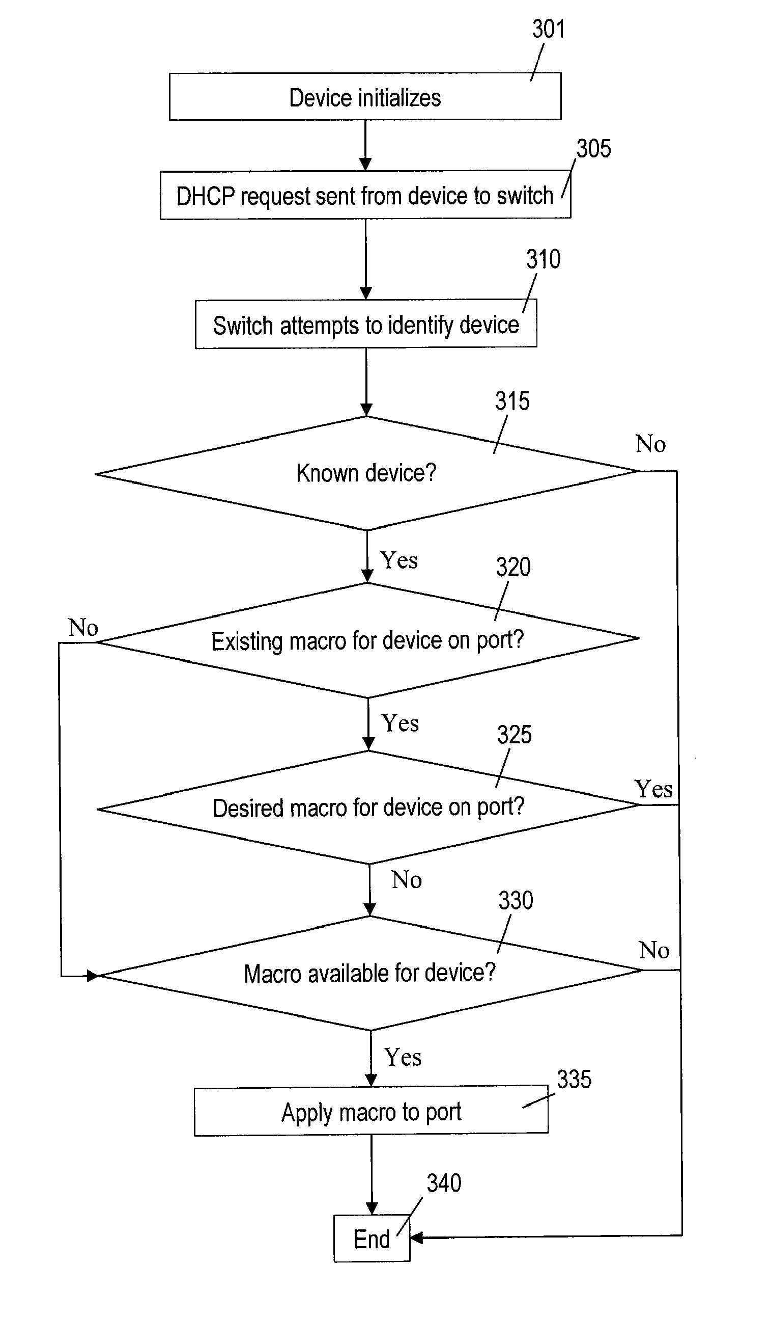
<figref idrefs="DRAWINGS">FIG. 3A</figref> is a flow chart that provides an overview of a method of the present invention.
<figref idrefs="DRAWINGS">FIG. 3B</figref> is a network diagram that illustrates an implementation of the method outlined in <figref idrefs="DRAWINGS">FIG. 3A</figref>.
<figref idrefs="DRAWINGS">FIG. 4</figref> is a flow chart that provides an overview of an alternative method of the present invention.
<figref idrefs="DRAWINGS">FIG. 5</figref> is a block diagram that illustrates a network device for implementing some aspects of the invention.
<figref idrefs="DRAWINGS">FIG. 6</figref> is a block diagram that illustrates another network device for implementing some aspects of the invention.
DETAILED DESCRIPTION OF THE INVENTION
In this application, numerous specific details are set forth in order to provide a thorough understanding of the present invention. It will be obvious, however, to one skilled in the art, that the present invention may be practiced without some or all of these specific details. In other instances, well known process steps have not been described in detail in order not to obscure the present invention.
Although the present invention involves methods and devices for identifying and provisioning individual RFID devices in a network, many aspects of the present invention can be applied to identifying and provisioning other types of devices in a network. Similarly, although much of the discussion herein applies to implementations using the DHCP protocol, the present invention is not protocol-specific and may be used, for example, in implementations using UPnP, 802.1ab or similar discovery protocols. Likewise, while the implementations described herein refer to exemplary DHCP Options, other DHCP Options may advantageously be used to implement the present invention.
Similarly, while some exemplary implementations of the invention involve using the SmartPorts™ “macro” functionality for configuring ports of network devices, other such tools could be used. In other implementations of the invention, a command line interface (“CLI”) or another programmatic interface such as Simple Network Management Protocol (“SNMP”) or Netconf® is used for this purpose.
Prior implementations of SmartPorts™ macros required users to manually identify connection types (e.g., RFID, manufacturing, IPphone) and then to configure a network device according to the identified connection type. As used herein, the term “macro” will sometimes be used to mean both the commands used to configure, e.g., a port of a network device and a configuration resulting from the application of such a macro. The network device could be configured, for example, using a command line interface or a network management tool such as CMS on a per-port basis.
An exemplary Cisco SmartPorts™ macro for configuring a port for an RFID device will now be described with reference to <figref idrefs="DRAWINGS">FIG. 2A</figref>. Line <b>201</b> is used to establish the macro's name, which in this case is RFID_Macro<b>1</b>. It is helpful to use a name that is easy to recognize as one type of macro for RFID devices, to allow for the possibility of having macros for multiple device types and multiple macros for RFID devices.
Line <b>203</b> will cause an RFID VLAN to be assigned and line <b>205</b> puts a switch port in “access” mode. Line <b>207</b> assigns a generic description to the interface indicating its use, which is a connection to an RFID device in this example. Lines <b>209</b> enable port security and limit the port to a single media access control (“MAC”) address.
According to line <b>211</b>, when the maximum number of MAC addresses is exceeded, traffic from additional source MAC addresses are dropped. In addition, an SNMP trap and a syslog message are generated. Lines <b>213</b> cause the secure MAC address to age out after 10 minutes of inactivity.
Lines <b>215</b> configure the port as an edge device port that does not need to behave according to a spanning tree protocol. Accordingly, bridge port data unit (“BPDU”) packets are not be allowed to enter the network from this port. “Spanning-tree portfast” allows the port to move into the forwarding state quickly.
Lines <b>217</b> set broadcast and multicast storm control limits to 20% of the interface bandwidth. As with other settings in this example, this limit should be based upon the anticipated requirements of the device to be in communication with the port. Line <b>219</b> applies a rate limiting of DHCP packets coming from the device to 100 packets per second.
Line <b>221</b> is one example of a QoS for the device. This QoS is applicable, for example, if the device is an RFID reader that sends packets marked with DSCP and if these values should be trusted.
<figref idrefs="DRAWINGS">FIG. 2B</figref> sets forth one example of how to apply the previously-described SmartPorts macro to a switch port. <figref idrefs="DRAWINGS">FIG. 2B</figref> is a screen capture of a CLI session for configuring a port. Line <b>251</b> identifies the switch to be configured (“DC_Switch<b>1</b>”). Line <b>255</b> is a prompt from switch DC_Switch<b>1</b>. Line <b>260</b> configures the interface as a Fast Ethernet interface.
Line <b>265</b> applies a selected macro, which is “RFID_Macro<b>1</b>” in this example, to the interface. The example assumes that VLAN <b>30</b> has previously been configured as the RFID VLAN. Line <b>270</b> is a command prompt from switch DC_Switch<b>1</b>.
Referring back to <figref idrefs="DRAWINGS">FIG. 1</figref>, for example, in order to configure port <b>120</b> using prior implementations of SmartPorts, a user (e.g., a network administrator) would need to manually go into every port, select a macro for each device (if one exists) and apply the appropriate macro to the port to which the device is connected. For example, the user would need to determine the appropriate port configuration for a connection with RFID reader <b>110</b>, determine whether a macro exists for this configuration, and, if so, apply the appropriate macro to configure port <b>120</b>. If no such macro existed, each attribute of the port configuration would need to be separately indicated.
Some exemplary implementations of the invention will now be described with reference to <figref idrefs="DRAWINGS">FIGS. 3A and 3B</figref>. <figref idrefs="DRAWINGS">FIG. 3A</figref> is a flow chart that outlines method <b>300</b> according to the invention. <figref idrefs="DRAWINGS">FIG. 3B</figref> is a simplified network diagram of network <b>350</b> that provides one example of how method <b>300</b> may be implemented.
Those of skill in the art will appreciate that some steps of the methods discussed herein, including method <b>300</b>, need not be performed (and in some implementations are not performed) in the order shown. Moreover, some implementations of the methods discussed herein may include more or fewer steps than those shown, e.g., in <figref idrefs="DRAWINGS">FIG. 3A</figref>.
Similarly, those of skill in the art will appreciate that the elements of <figref idrefs="DRAWINGS">FIG. 3B</figref> are both simplified and merely illustrative. <figref idrefs="DRAWINGS">FIG. 3B</figref> illustrates switches <b>365</b>, <b>380</b> and <b>385</b>, all of which have attached devices. In this example, switch <b>365</b> is a Cisco Catalyst 4500 Series switch and switches <b>380</b> and <b>385</b> are Cisco Catalyst 3750 Series switches. However, one of skill in the art will appreciate that other types of network devices could be used to implement the invention. Moreover, switches <b>365</b>, <b>380</b> and <b>385</b> could be in the same location (e.g., in the same warehouse or factory) or could be in different locations. Switches <b>365</b>, <b>380</b> and <b>385</b> can communicate with DHCP server <b>370</b>, host device <b>390</b> and storage devices <b>395</b> via network <b>375</b>. Accordingly, network <b>375</b> may include portions of one or more private networks and part of the Internet.
The devices attached to switches <b>365</b>, <b>380</b> and <b>385</b> are not necessarily all of the same type. In this example, device <b>355</b> is an RFID reader and device <b>357</b> is an IP telephone. As discussed elsewhere herein, even devices that are of the same general type may have different capabilities and/or different desired functions.
A device that sends out an initiation for an IP address to a DHCP server does so by way of a packet that includes a “DHCPDISCOVER” request. This command includes, inter alia, the media access control (“MAC”) address of the device. RFC 2131 is hereby incorporated by reference.
Accordingly, in step <b>301</b> of method <b>300</b>, device <b>355</b> of <figref idrefs="DRAWINGS">FIG. 3B</figref> initializes and then sends DHCPDISCOVER request <b>356</b> to port <b>360</b> of switch <b>365</b>. Switch <b>365</b> is configured not only to forward DHCPDISCOVER request <b>356</b> to DHCP server <b>370</b> via network <b>375</b>, but also to analyze the contents of DHCPDISCOVER request <b>356</b>. The steps performed by switch <b>365</b> according to method <b>300</b> may be controlled by one or more logic devices <b>368</b>, which is an ASIC in this example. However, logic device(s) <b>368</b> could be any convenient logic device(s).
In step <b>315</b>, switch <b>365</b> attempts to identify device <b>355</b> according to information in DHCPDISCOVER request <b>356</b>. In this example, switch <b>365</b> applies “snooping” techniques to analyze the contents of Options in DHCPDISCOVER request <b>356</b>. Switch <b>365</b> may, for example, examine the contents of DHCP Option 60 to determine a device type or vendor identifier. RFC 2132 is hereby incorporated by reference. Switch <b>365</b> may examine the “Enterprise number” field of DHCP Option 125 to determine the EPCGlobal enterprise number of the device. RFC 3925 is hereby incorporated by reference.
Alternatively, or additionally, switch <b>365</b> may examine other DHCP options. For example, switch <b>365</b> may examine DHCP Option 150 to identify device <b>355</b>; this Option is used, for example, by IPPhones provided by Cisco Systems, Inc. R. Johnson's draft “TFTP Server Address DHCP Option” (Network Working Group Feb. 6, 2005) describes relevant information and is hereby incorporated by reference. Switch <b>365</b> may examine a “PXE boot” option to determine an appropriate configuration for port <b>360</b>. M. Johnston's draft “DHCP Preboot execution Environment (PXE) Options” (Dynamic Host Configuration Working Group Jan. 21, 2005) describes relevant information and is hereby incorporated by reference. Switch <b>365</b> may examine Option 43 to obtain vendor-specific information regarding device <b>355</b>. Switch <b>365</b> may examine Option 61 to determine an EPC identifier of device <b>355</b>.
In some implementations, switch <b>365</b> also determines an appropriate personality for device <b>355</b> in step <b>315</b>. In some such implementations, switch <b>365</b> examines the DHCP Option 77 to determine a device personality. In other implementations, switch <b>365</b> can determine an appropriate personality for device <b>355</b> indirectly, e.g., by cross-referencing a look-up table or a similar data structure based on other information in DHCPDISCOVER request <b>356</b>. The look-up table could be stored locally (e.g., in memory <b>367</b>), on an attached device or on another device that switch <b>365</b> can access via network <b>375</b>, part of which is the Internet in this example.
If switch <b>365</b> cannot identify device <b>355</b>, the process ends in this example (step <b>340</b> of <figref idrefs="DRAWINGS">FIG. 3A</figref>). Alternatively (or additionally), a network administrator could be alerted, e.g., by causing switch <b>365</b> to send a message to host device <b>390</b>.
However, if switch <b>365</b> can identify the device, the method proceeds to step <b>320</b>, wherein switch <b>365</b> determines port <b>360</b> is already configured. (In the flow chart of <figref idrefs="DRAWINGS">FIG. 3A</figref> it is presumed that a port configuration (if any) has resulted from the application of a macro, though this need not be the case.)
If port <b>360</b> has not yet been configured, it is determined whether there is a configuration macro available (e.g., locally available and stored in memory <b>367</b>) that is appropriate for device <b>355</b>. (Step <b>330</b>.) Table <b>366</b> is one exemplary data structure that may be used for such a purpose. Table <b>366</b> includes macro field <b>372</b>, for defining a plurality of configuration macros, each of which corresponds to a device of device ID field <b>374</b>. Accordingly, a device ID determined as described above with reference to step <b>315</b> (or otherwise) can be used to determine whether there is a corresponding macro.
If port <b>360</b> is already configured, it is determined in step <b>325</b> whether the configuration is suitable for the device identified in step <b>315</b>. If so, the process ends.
If the port does not have a desired configuration, it is determined in step <b>330</b> whether there is an appropriate macro available for the device. If there is an appropriate macro available for the device, the macro is applied (step <b>335</b>) and then the process ends (step <b>340</b>). If not, the process ends without a macro being applied. Preferably, a network administrator is notified, e.g., by sending a message from switch <b>365</b> to host device <b>390</b>.
In the preceding example, switch <b>365</b> had the intelligence for determining how to automatically configure a port on which a DHCPDISCOVER request is received. The switch itself analyzed the DHCPDISCOVER request and configured the port with an appropriate combination of attributes. These combinations of attributes, along with the necessary software for applying them, were stored in the switch itself.
However, in other implementations of the invention, both the intelligence for determining how appropriately to configure the port and the instructions for so configuring the port may be owned by another device. For example, the intelligence may reside in DHCP server <b>370</b>, an edge services management server, an authentication server and a device dedicated to port configuration. Some such implementations are illustrated by the flow chart of <figref idrefs="DRAWINGS">FIG. 4</figref>.
In steps <b>401</b> and <b>405</b>, a device initializes and sends a DHCPDISCOVER request to a switch port. In this example, switch <b>365</b> forwards the DHCPDISCOVER request with an indication of the port on which the DHCPDISCOVER request was received. (Step <b>410</b>.) The port ID could be provided, for example, in DHCP Option 82. Preferably, the switch also forwards information regarding the current port configuration to DHCP server <b>370</b>.
According to some implementations, DHCP server <b>370</b> attempts to identify the device. (Step <b>412</b>.) If DHCP server <b>370</b> can identify the device, DHCP server <b>370</b> performs steps <b>420</b>, <b>425</b> and <b>430</b>, which are analogous to steps <b>320</b> through <b>330</b> of method <b>300</b>.
DHCP server <b>370</b> then instructs switch <b>365</b> to configure the port in an appropriate manner, e.g., by applying a macro. (Step <b>435</b>.) Macros (or the like) for this purpose could be stored in switch <b>365</b>, could be sent from DHCP server <b>370</b> to switch <b>365</b>, or could be obtained by switch <b>365</b> from another device. For example, DHCP server <b>370</b> could send switch <b>365</b> a pointer to a memory space wherein such instructions are stored (e.g., in one of storage devices <b>395</b>).
In other implementations, DHCP server <b>370</b> provides an IP address in response to the DHCPDISCOVER request and forwards the DHCPDISCOVER request to another device that performs steps similar to steps <b>310</b> through <b>330</b>. The device could be, e.g., an authentication server or a server that is dedicated to automated port configuration. This device could instruct switch <b>365</b> to configure the port in an appropriate manner, e.g., as described above.
Alternatively, DHCP server <b>370</b> could perform at least the device and port identification steps. DHCP server <b>370</b> could then forward this information to another device that first performs a mapping of device type to desired configuration and then instructs switch <b>365</b> to configure port <b>360</b> accordingly.
In yet other implementations, a device local to switch <b>365</b> performs steps similar to those of steps <b>315</b> through <b>330</b> and then instructs switch <b>365</b> accordingly. For example, a DHCP relay agent in switch <b>365</b> is programmed to forward a copy of the DHCPDISCOVER request to another device (e.g., an edge services management server) that performs steps similar to steps <b>310</b> through <b>330</b>, e.g., prior to forwarding the DHCPDISCOVER request to the DHCP server. In such implementations, the DHCP server could behave as a normal DHCP server and switch <b>365</b> could lack the intelligence to perform steps <b>310</b> through <b>330</b>. The DHCPDISCOVER request could be forwarded to another device on the local network that performs steps similar to steps <b>310</b> through <b>330</b>.
However, as illustrated in <figref idrefs="DRAWINGS">FIG. 5</figref>, some embodiments of the invention combine many of the components necessary to implement the invention within a single chassis. Here, chassis <b>500</b> is a router that includes switch module <b>505</b>, with ports <b>510</b> that can be configured for appropriately communicating with devices <b>515</b>. In this example, router <b>500</b> also includes DHCP server <b>520</b>, which may be implemented in software and/or hardware (e.g., as a line card or “blade”). In alternative implementations, DHCP server <b>520</b> could be implemented in a separate device that is in communication with router <b>500</b>.
Instead of being implemented in a router having a switch module, alternative embodiments of the invention provide a chassis <b>500</b> that is a switch that runs Layer <b>3</b>, running IOS. As above, chassis <b>500</b> could also include DHCP server <b>520</b>, implemented in software and/or hardware, or DHCP server <b>520</b> could be implemented in a separate device that is in communication with chassis <b>500</b>.
It will be appreciated by those of skill in the art that other types of devices, including but not limited to point-of-sale devices (e.g., “cash registers”) VoIP telephones and devices used in manufacturing, may be advantageously configured according to the methods of the present invention. For example, one or more defined fields could indicate the type of device, device personality, etc.
In one such example, DHCP Option 60 could indicate that the device is a cash register and DHCP Option 77 could indicate the “personality” of the cash register, e.g., that it is a cash register used by a particular type of restaurant. There could be predefined macros for configuring a switch port appropriately for each type of device, e.g., for a cash register.
<figref idrefs="DRAWINGS">FIG. 6</figref> illustrates an example of a network device that may be configured to implement some methods of the present invention. Network device <b>660</b> includes a master central processing unit (CPU) <b>662</b>, interfaces <b>668</b>, and a bus <b>667</b> (e.g., a PCI bus). Generally, interfaces <b>668</b> include ports <b>669</b> appropriate for communication with the appropriate media.
The interfaces <b>668</b> are typically provided as interface cards (sometimes referred to as “line cards” or network interface cards (NICs)) <b>670</b>. Generally, line cards <b>670</b> control the sending and receiving of data packets over the network and sometimes support other peripherals used with the network device <b>660</b>. Among the interfaces that may be provided are Fibre Channel (“FC”) interfaces, Ethernet interfaces, frame relay interfaces, cable interfaces, DSL interfaces, token ring interfaces, and the like. In addition, various very high-speed interfaces may be provided, such as fast Ethernet interfaces, Gigabit Ethernet interfaces, ATM interfaces, HSSI interfaces, POS interfaces, FDDI interfaces, ASI interfaces, DHEI interfaces and the like.
In some embodiments, one or more of line cards <b>670</b> includes at least one independent processor <b>674</b> and, in some instances, volatile RAM. Independent processors <b>674</b> may be, for example ASICs or any other appropriate processors. According to some such embodiments, these independent processors <b>674</b> perform at least some of the functions of the logic described herein. In some embodiments, one or more of interfaces <b>668</b> control such communications-intensive tasks as media control and management. By providing separate processors for the communications-intensive tasks, line cards allow the master microprocessor <b>662</b> efficiently to perform other functions such as routing computations, network diagnostics, security functions, etc.
When acting under the control of appropriate software or firmware, in some implementations of the invention CPU <b>662</b> may be responsible for implementing specific functions associated with the functions of a desired network device. According to some embodiments, CPU <b>662</b> accomplishes all these functions under the control of software including an operating system (e.g. Linux, VxWorks, etc.), and any appropriate applications software.
CPU <b>662</b> may include one or more processors <b>663</b> such as a processor from the Motorola family of microprocessors or the MIPS family of microprocessors. In an alternative embodiment, processor <b>663</b> is specially designed hardware for controlling the operations of network device <b>660</b>. In a specific embodiment, a memory <b>661</b> (such as non-volatile RAM and/or ROM) also forms part of CPU <b>662</b>. However, there are many different ways in which memory could be coupled to the system. Memory block <b>661</b> may be used for a variety of purposes such as, for example, caching and/or storing data, programming instructions, etc.
Regardless of network device's configuration, it may employ one or more memories or memory modules (such as, for example, memory block <b>665</b>) configured to store data, program instructions for the general-purpose network operations and/or other information relating to the functionality of the techniques described herein. The program instructions may control the operation of an operating system and/or one or more applications, for example.
Because such information and program instructions may be employed to implement the systems/methods described herein, the present invention relates to machine-readable media that include program instructions, state information, etc. for performing various operations described herein. Examples of machine-readable media include, but are not limited to, magnetic media such as hard disks, floppy disks, and magnetic tape; optical media such as CD-ROM disks; magneto-optical media; and hardware devices that are specially configured to store and perform program instructions, such as read-only memory devices (ROM) and random access memory (RAM). The invention may also be embodied in a carrier wave traveling over an appropriate medium such as airwaves, optical lines, electric lines, etc. Examples of program instructions include both machine code, such as produced by a compiler, and files containing higher level code that may be executed by the computer using an interpreter.
Although the system shown in <figref idrefs="DRAWINGS">FIG. 6</figref> illustrates one specific network device of the present invention, it is by no means the only network device architecture on which the present invention can be implemented. For example, an architecture having a single processor that handles communications as well as routing computations, etc. is often used. Further, other types of interfaces and media could also be used with the network device. The communication path between interfaces/line cards may be bus based (as shown in <figref idrefs="DRAWINGS">FIG. 6</figref>) or switch fabric based (such as a cross-bar).
Other Embodiments
Although illustrative embodiments and applications of this invention are shown and described herein, many variations and modifications are possible which remain within the concept, scope, and spirit of the invention, and these variations would become clear to those of ordinary skill in the art after perusal of this application. Accordingly, the present embodiments are to be considered as illustrative and not restrictive, and the invention is not to be limited to the details given herein, but may be modified within the scope and equivalents of the appended claims.
Contents5
9 sheets
Sheet 1 Sheet 2 Sheet 3 Sheet 4 Sheet 5 Sheet 6 Sheet 7 Sheet 8 Sheet 9
Every citation, both waysCites: the store holds 110 of 111
| Document | Relation | Office | Cited during |
|---|---|---|---|
| US9806986B2 | Cited by | United States of America | Applicant |
| US2007109100A1 | Cited by | United States of America | Pre-grant |
| US9064164B2 | Cited by | United States of America | Applicant |
| US9083650B2 | Cited by | United States of America | Search report |
| US2011035672A1 | Cited by | United States of America | Pre-grant |
| US8824297B2 | Cited by | United States of America | Applicant |
| US2006033606A1 | Cited by | United States of America | Pre-grant |
| US8249953B2 | Cited by | United States of America | Applicant |
| US8566460B1 | Cited by | United States of America | Search report |
| US2012221742A1 | Cited by | United States of America | Pre-grant |
| US9813503B2 | Cited by | United States of America | Search report |
| US8700778B2 | Cited by | United States of America | Applicant |
| US8843598B2 | Cited by | United States of America | Applicant |
| US2014108624A1 | Cited by | United States of America | Pre-grant |
| US8698603B2 | Cited by | United States of America | Applicant |
| US2010137024A1 | Cited by | United States of America | Pre-grant |
| US8604910B2 | Cited by | United States of America | Applicant |
| US2010103910A1 | Cited by | United States of America | Pre-grant |
| US2003126248A1 | Cites | United States of America | Search report |
| US2004073600A1 | Cites | United States of America | Search report |
| US2005080881A1 | Cites | United States of America | Search report |
| US2005102406A1 | Cites | United States of America | Search report |
| US2005228887A1 | Cites | United States of America | Search report |
| US2006259183A1 | Cites | United States of America | Search report |
| US2009049191A1 | Cites | United States of America | Search report |
| US4625081A | Cites | United States of America | Applicant |
| US4688026A | Cites | United States of America | Applicant |
| US5339073A | Cites | United States of America | Applicant |
| US5574722A | Cites | United States of America | Applicant |
| US5588009A | Cites | United States of America | Applicant |
| US5646616A | Cites | United States of America | Applicant |
| US5790542A | Cites | United States of America | Applicant |
| US5796743A | Cites | United States of America | Applicant |
| US5819042A | Cites | United States of America | Applicant |
| US5832503A | Cites | United States of America | Applicant |
| US5850187A | Cites | United States of America | Applicant |
| US5887176A | Cites | United States of America | Applicant |
| US6012090A | Cites | United States of America | Applicant |
| US6021135A | Cites | United States of America | Applicant |
| US6070187A | Cites | United States of America | Search report |
| US6111517A | Cites | United States of America | Applicant |
| US6115079A | Cites | United States of America | Applicant |
| US6115378A | Cites | United States of America | Applicant |
| US6125391A | Cites | United States of America | Applicant |
| US6145079A | Cites | United States of America | Applicant |
| US6212563B1 | Cites | United States of America | Applicant |
| US6226675B1 | Cites | United States of America | Applicant |
| US6300903B1 | Cites | United States of America | Applicant |
| US6321264B1 | Cites | United States of America | Applicant |
| US6324575B1 | Cites | United States of America | Search report |
| US6330597B2 | Cites | United States of America | Search report |
| US6337856B1 | Cites | United States of America | Applicant |
| US6341130B1 | Cites | United States of America | Applicant |
| US6356951B1 | Cites | United States of America | Applicant |
| US6363477B1 | Cites | United States of America | Applicant |
| US6393458B1 | Cites | United States of America | Applicant |
| US6473858B1 | Cites | United States of America | Applicant |
| US6510434B1 | Cites | United States of America | Applicant |
| US6510464B1 | Cites | United States of America | Applicant |
| US6539281B2 | Cites | United States of America | Applicant |
| US6553489B1 | Cites | United States of America | Applicant |
| US6587431B1 | Cites | United States of America | Applicant |
| US6587874B1 | Cites | United States of America | Applicant |
| US6597918B1 | Cites | United States of America | Applicant |
| US6611526B1 | Cites | United States of America | Applicant |
| US6665713B1 | Cites | United States of America | Applicant |
| US6677852B1 | Cites | United States of America | Applicant |
| US6678827B1 | Cites | United States of America | Applicant |
| US6683881B1 | Cites | United States of America | Applicant |
| US6718326B2 | Cites | United States of America | Applicant |
| US6745041B2 | Cites | United States of America | Applicant |
| US6772204B1 | Cites | United States of America | Applicant |
| US6772211B2 | Cites | United States of America | Applicant |
| US6772223B1 | Cites | United States of America | Applicant |
| US6785732B1 | Cites | United States of America | Applicant |
| US6792002B2 | Cites | United States of America | Applicant |
| US6810040B1 | Cites | United States of America | Applicant |
| US6816455B2 | Cites | United States of America | Applicant |
| US6843121B1 | Cites | United States of America | Applicant |
| US6862270B1 | Cites | United States of America | Applicant |
| US6868426B1 | Cites | United States of America | Applicant |
| US6912213B2 | Cites | United States of America | Applicant |
| US6931574B1 | Cites | United States of America | Applicant |
| US6963282B1 | Cites | United States of America | Applicant |
| US6965599B1 | Cites | United States of America | Applicant |
| US6995655B2 | Cites | United States of America | Applicant |
| US6996842B2 | Cites | United States of America | Applicant |
| US7002907B1 | Cites | United States of America | Applicant |
| US7032031B2 | Cites | United States of America | Applicant |
| US7038573B2 | Cites | United States of America | Applicant |
| US7054924B1 | Cites | United States of America | Applicant |
| US7057511B2 | Cites | United States of America | Applicant |
| US7058973B1 | Cites | United States of America | Applicant |
| US7064660B2 | Cites | United States of America | Applicant |
| US7075412B1 | Cites | United States of America | Applicant |
| US7081819B2 | Cites | United States of America | Applicant |
| US7089586B2 | Cites | United States of America | Applicant |
| US7103040B2 | Cites | United States of America | Applicant |
| US7103886B2 | Cites | United States of America | Applicant |
| US7111076B2 | Cites | United States of America | Applicant |
65 members in 6 offices
Priority claims6
| Document | Office | Kind | Date |
|---|---|---|---|
| 57099904 | United States of America | P | |
| 57099904 | United States of America | P | |
| 10414005 | United States of America | A | |
| 60570999 | – | – | – |
| US20040570999P | – | – | – |
| US20050104140 | – | – | – |
Members65
| Document | Office | Kind | |
|---|---|---|---|
| US2005252957A1 | United States of America | A1 | |
| US2005252970A1 | United States of America | A1 | |
| US2005252971A1 | United States of America | A1 | |
| US2005253717A1 | United States of America | A1 | |
| US2005253718A1 | United States of America | A1 | |
| US2005253722A1 | United States of America | A1 | |
| AU2005246794A1 | Australia | A1 | |
| AU2005246794A2 | Australia | A2 | |
| CA2565099A1 | Canada | A1 | |
| CA2565451A1 | Canada | A1 | |
| CA2565456A1 | Canada | A1 | |
| US2005264420A1 | United States of America | A1 | |
| WO2005114545A2 | World Intellectual Property Organization (WIPO) | A2 | |
| WO2005114602A2 | World Intellectual Property Organization (WIPO) | A2 | |
| WO2005114603A2 | World Intellectual Property Organization (WIPO) | A2 | |
| WO2005114604A2 | World Intellectual Property Organization (WIPO) | A2 | |
| WO2005114545A8 | World Intellectual Property Organization (WIPO) | A8 | |
| WO2005114545A3 | World Intellectual Property Organization (WIPO) | A3 | |
| WO2005114603A8 | World Intellectual Property Organization (WIPO) | A8 | |
| US2006033606A1 | United States of America | A1 | |
| WO2005114602A3 | World Intellectual Property Organization (WIPO) | A3 | |
| US2006091999A1 | United States of America | A1 | |
| WO2005114603A3 | World Intellectual Property Organization (WIPO) | A3 | |
| US2006266832A1 | United States of America | A1 | |
| EP1751687A2 | European Patent Office (EPO) | A2 | |
| EP1759328A2 | European Patent Office (EPO) | A2 | |
| EP1761881A2 | European Patent Office (EPO) | A2 | |
| EP1763856A2 | European Patent Office (EPO) | A2 | |
| CN1954327A | China | A | |
| CN1954328A | China | A | |
| CN1954329A | China | A | |
| WO2005114604A3 | World Intellectual Property Organization (WIPO) | A3 | |
| US7322523B2 | United States of America | B2 | |
| US7325734B2 | United States of America | B2 | |
| WO2008016488A2 | World Intellectual Property Organization (WIPO) | A2 | |
| US7336175B2 | United States of America | B2 | |
| US2008087730A1 | United States of America | A1 | |
| WO2008016488A3 | World Intellectual Property Organization (WIPO) | A3 | |
| US2008197980A1 | United States of America | A1 | |
| US7422152B2 | United States of America | B2 | |
| CN101263506A | China | A | |
| EP2047440A2 | European Patent Office (EPO) | A2 | |
| CN100531082C | China | C | |
| CN100531083C | China | C | |
| CA2565456C | Canada | C | |
| CN100561499C | China | C | |
| US7648070B2 | United States of America | B2 | |
| US7658319B2 | United States of America | B2 | |
| AU2005246794B2 | Australia | B2 | |
| US7789308B2 | United States of America | B2 | |
| EP1751687A4 | European Patent Office (EPO) | A4 | |
| EP1759328A4 | European Patent Office (EPO) | A4 | |
| EP1761881A4 | European Patent Office (EPO) | A4 | |
| EP1763856A4 | European Patent Office (EPO) | A4 | |
| CN101263506B | China | B | |
| US8060623B2This record | United States of America | B2 | |
| US2012036243A1 | United States of America | A1 | |
| US8113418B2 | United States of America | B2 | |
| US8249953B2 | United States of America | B2 | |
| US8601143B2 | United States of America | B2 | |
| US8604910B2 | United States of America | B2 | |
| CA2565451C | Canada | C | |
| CA2565099C | Canada | C | |
| EP1763856B1 | European Patent Office (EPO) | B1 | |
| EP1759328B1 | European Patent Office (EPO) | B1 |
119 transactions on the USPTO file
Allowed after 3 non-final rejections, 2 final rejections, 1 RCE and 1 appeal.
- Non-final rejections
- 3
- Final rejections
- 2
- RCEs
- 1
- Appeals
- 1
Over time
Point at a mark for the transactionTransactions
| Event | Code | |
|---|---|---|
| Payment of Maintenance Fee, 12th Year, Large EntityM1553 | M1553 | |
| Email NotificationEML_NTR | EML_NTR | |
| Change in Power of Attorney (May Include Associate POA)PA.. | PA.. | |
| Correspondence Address ChangeC.AD | C.AD | |
| Payment of Maintenance Fee, 8th Year, Large EntityM1552 | M1552 | |
| Recordation of Patent Grant MailedPGM/ | PGM/ | |
| Patent Issue Date Used in PTA CalculationAllowedPTAC | PTAC | |
| Email NotificationEML_NTR | EML_NTR | |
| Issue Notification MailedAllowedWPIR | WPIR | |
| Dispatch to FDCD1935 | D1935 | |
| Application Is Considered Ready for IssuePILS | PILS | |
| Response to Reasons for AllowanceREAS | REAS | |
| Issue Fee Payment VerifiedN084 | N084 | |
| Issue Fee Payment ReceivedIFEE | IFEE | |
| Email NotificationEML_NTR | EML_NTR | |
| Mailing Corrected Notice of AllowabilityMCNOA | MCNOA | |
| Examiner's Amendment CommunicationEX.A | EX.A | |
| Corrected Notice of AllowabilityCNOA | CNOA | |
| Pubs Case Remand to TCPUBTC | PUBTC | |
| Response to Reasons for AllowanceREAS | REAS | |
| Electronic ReviewELC_RVW | ELC_RVW | |
| Email NotificationEML_NTF | EML_NTF | |
| Mail Notice of AllowanceAllowedMN/=. | MN/=. | |
| Notice of Allowance Data Verification CompletedAllowedN/=. | N/=. | |
| Reasons for AllowanceEX.R | EX.R | |
| Examiner's Amendment CommunicationEX.A | EX.A | |
| Examiner Interview Summary Record (PTOL - 413)EXIN | EXIN | |
| Date Forwarded to ExaminerFWDX | FWDX | |
| Response to Election / Restriction FiledELC. | ELC. | |
| Electronic ReviewELC_RVW | ELC_RVW | |
| Email NotificationEML_NTF | EML_NTF | |
| Mail Restriction RequirementMCTRS | MCTRS | |
| Restriction/Election RequirementCTRS | CTRS | |
| Date Forwarded to ExaminerFWDX | FWDX | |
| Information Disclosure Statement consideredIDSC | IDSC | |
| Reference capture on IDSRCAP | RCAP | |
| Information Disclosure Statement (IDS) FiledM844 | M844 | |
| Information Disclosure Statement (IDS) FiledWIDS | WIDS | |
| Correspondence Address ChangeC.ADB | C.ADB | |
| Response after Non-Final ActionA... | A... | |
| Electronic ReviewELC_RVW | ELC_RVW | |
| Email NotificationEML_NTF | EML_NTF | |
| Mail Non-Final RejectionNon-final rejectionMCTNF | MCTNF | |
| Non-Final RejectionNon-final rejectionCTNF | CTNF | |
| Date Forwarded to ExaminerFWDX | FWDX | |
| Appeal Brief Review CompleteAPBR | APBR | |
| Appeal Brief FiledAP.B | AP.B | |
| Request for Extension of Time - GrantedXT/G | XT/G | |
| Mail Appeals conf. Proceed to BPAIMAPCP | MAPCP | |
| Pre-Appeals Conference Decision - Proceed to BPAIAPCP | APCP | |
| Request for Pre-Appeal Conference FiledAP.C | AP.C | |
| Notice of Appeal FiledN/AP | N/AP | |
| Electronic ReviewELC_RVW | ELC_RVW | |
| Email NotificationEML_NTF | EML_NTF | |
| Mail Final Rejection (PTOL - 326)Final rejectionMCTFR | MCTFR | |
| Final RejectionFinal rejectionCTFR | CTFR | |
| Date Forwarded to ExaminerFWDX | FWDX | |
| Response after Non-Final ActionA... | A... | |
| Mail Non-Final RejectionNon-final rejectionMCTNF | MCTNF | |
| Non-Final RejectionNon-final rejectionCTNF | CTNF | |
| Mail Examiner Interview Summary (PTOL - 413)MEXIN | MEXIN | |
| Date Forwarded to ExaminerFWDX | FWDX | |
| Date Forwarded to ExaminerFWDX | FWDX | |
| Disposal for a RCE / CPA / R129AbandonedABN9 | ABN9 | |
| Examiner Interview Summary Record (PTOL - 413)EXIN | EXIN | |
| Request for Continued Examination (RCE)RCEX | RCEX | |
| Workflow - Request for RCE - BeginBRCE | BRCE | |
| Case Docketed to Examiner in GAUDOCK | DOCK | |
| Mail Final Rejection (PTOL - 326)Final rejectionMCTFR | MCTFR | |
| Final RejectionFinal rejectionCTFR | CTFR | |
| Date Forwarded to ExaminerFWDX | FWDX | |
| Information Disclosure Statement consideredIDSC | IDSC | |
| Reference capture on IDSRCAP | RCAP | |
| Information Disclosure Statement (IDS) FiledM844 | M844 | |
| New or Additional Drawing FiledC614 | C614 | |
| Response after Non-Final ActionA... | A... | |
| Information Disclosure Statement (IDS) FiledWIDS | WIDS | |
| Mail Non-Final RejectionNon-final rejectionMCTNF | MCTNF | |
| Non-Final RejectionNon-final rejectionCTNF | CTNF | |
| Case Docketed to Examiner in GAUDOCK | DOCK | |
| Information Disclosure Statement consideredIDSC | IDSC | |
| Information Disclosure Statement (IDS) FiledM844 | M844 | |
| Information Disclosure Statement (IDS) FiledWIDS | WIDS | |
| Information Disclosure Statement consideredIDSC | IDSC | |
| Information Disclosure Statement consideredIDSC | IDSC | |
| Reference capture on IDSRCAP | RCAP | |
| Information Disclosure Statement (IDS) FiledM844 | M844 | |
| Information Disclosure Statement (IDS) FiledWIDS | WIDS | |
| Information Disclosure Statement (IDS) FiledWIDS | WIDS | |
| Information Disclosure Statement consideredIDSC | IDSC | |
| Reference capture on IDSRCAP | RCAP | |
| Electronic Information Disclosure StatementEIDS. | EIDS. | |
| Information Disclosure Statement (IDS) FiledWIDS | WIDS | |
| Information Disclosure Statement consideredIDSC | IDSC | |
| Reference capture on IDSRCAP | RCAP | |
| Information Disclosure Statement (IDS) FiledM844 | M844 | |
| Information Disclosure Statement (IDS) FiledWIDS | WIDS | |
| Case Docketed to Examiner in GAUDOCK | DOCK | |
| Information Disclosure Statement consideredIDSC | IDSC | |
| Reference capture on IDSRCAP | RCAP |
6 legal events, as the office reported them to INPADOC
Over the term
Point at a mark for the eventEvents
| Event | Code | |
|---|---|---|
| Maintenance fee paymentMAFP | MAFP | |
| Maintenance fee paymentMAFP | MAFP | |
| Fee paymentFPAY | FPAY | |
| Information on status: patent grantGrantedPATENTED CASESTCF | STCF | |
| AssignmentAS | AS | |
| AssignmentAS | AS |
Numbers
- Publication
- 08060623
- Publication, DOCDB
- 8060623
- Publication, EPODOC
- US8060623
- Application
- 11104140
- Application, DOCDB
- 10414005
- Application, EPODOC
- US20050104140
Titles
- English
- Automated configuration of network device ports
Patent term adjustment
- A delay
- +705 daysthe office missed an examination deadline
- B delay
- +269 dayspendency past three years
- Overlap
- −31 daysdelays counted once
- Applicant delay
- −7 days
- Net adjustment
- 936 days
Classification
- CPC, 15
- G08B13/2402
- H04L41/0806
- H04L41/0843
- H04L41/0883
- H04W4/00
- H04W8/26
- H04L67/1021
- H04L61/4511
- H04L61/5007
- H04L2101/604
- H04L2101/663
- H04L61/5014
- H04L67/1001
- H04W28/088
- H04L41/12
- IPC, 11
- G06F15 177
- G06F15 16
- G06F15 173
- G06K7 08
- G08B13 14
- G08B13 24
- H04L12 24
- H04L12 28
- H04L12 56
- H04L29 08
- H04L29 12
- USPC, 9
- 709228000
- 370401000
- 709220000
- 709221000
- 709222000
- 709223000
- 709224000
- 709225000
- 709226000