Methods and systems for automatic device provisioning in an RFID network using IP multicast
Summary by NHIP
RFID Reader IP Multicast Provisioning
The method provisions an RFID device by reading an affixed tag and transmitting its data via IP multicast to a personality class appliance. The appliance returns configuration parameters for a specific personality class through a unicast IP message to complete automatic setup.
Claim Score by NHIP
Abstract
Methods and systems for automatic provisioning of RFID devices in an RFID network are described. A device, such as a Reader, has within its read field a special EPC Identity (ID) Tag that is specifically encoded for that Reader. When the Reader boots up, it reads the special ID Tag. The Tag has fields formatted according to the EPCglobal standards and certain bits within one of the fields indicates that the Tag is an EPC ID Tag and the data contained in the Tag will be used to provision the Reader. The Reader transmits an IP multicast packet containing data from the Tag to a network device referred to as a personality class appliance which receives the IP multicast packet. Thus, the Reader is an IP multicast sender and the appliance is an IP multicast receiver. Upon receiving the packet, the appliance retrieves configuration parameters for the Reader. These parameters collectively make up a personality class for the Reader. The personality data are transmitted back to the Reader via a unicast message. Once the Reader receives the configuration data, it provisions itself, becomes connected to the RFID network, and is ready for operation. RFID Readers and other devices can be provisioned automatically for a specific role when turned on, without requiring any manual configuration or data entry.
Term
Projected expiry 22 August 2031.
- Priority
- Filed
- Granted
- Today
- Projected expiry
23 claims: 6 independent, 17 dependent
- 1A method of provisioning a radio frequency identification (“RFID”) device, the method comprising:reading an affixed RFID Tag associated with the RFID device;transmitting a first data packet via Internet Protocol (IP) multicasting containing data stored on the affixed RFID Tag, the first data packet indicating one of a plurality of personality classes of RFID devices, the one of the plurality of personality classes of RFID devices being a personality class in which the RFID device is classified;and receiving a second data packet containing configuration parameters that correspond to the one of a plurality of personality classes of RFID devices, wherein the configuration parameters enable automatic provisioning of the RFID device for a specific function performed by the RFID devices in the one of the plurality of personality classes.
- 8A method of provisioning a radio frequency identification (“RFID”) device, the method comprising:receiving a first data packet via Internet Protocol (IP) multicast from the RFID device having a specific role performed by one of a plurality of classes of RFID devices;reading a value in the first data packet, the value indicating the one of the plurality of classes of RFID devices to which the RFID device belongs;retrieving configuration parameters for the one of a plurality of classes of RFID devices based on the value in the first data packet;and transmitting the configuration parameters to the RFID device, wherein the configuration parameters enable automatic provisioning of the RFID device to perform for the specific role of the one of the plurality of classes of RFID devices.
- 12Broadest claimClaim Score 76, broad(NHIP)A radio frequency identification (“RFID”) Tag comprising:a first field for identifying the RFID Tag as a certain type of Tag;a second field for classifying an associated RFID device as one of a plurality of personality classes of RFID devices;and a third field for storing a serial number that uniquely identifies the RFID Tag;wherein the tag is affixed to the RFID device.
- 19A radio frequency identification (“RFID”) network comprising:at least one RFID device having a read field;at least one Electronic Product Code (EPC) Tag associated with the at least one RFID device and within the read field of the device, wherein the at least one EPC Tag associated with the at least one RFID device includes a field indicating one of a plurality of personality classes of RFID devices;and a network component having access to configuration parameters for the at least one RFID device such that a different set of configuration parameters is stored in association with each one of the plurality of personality classes of RFID devices, wherein connectivity between the RFID device and the network device is Internet Protocol (IP) multicast enabled.
- 22A radio frequency identification (RFID) device comprising:an Electronic Product Code (EPC) Tag storing a first value indicating that the EPC Tag is an Identity Tag and a second value indicating a personality class of the device, the personality class of the device being one of a plurality of personality classes;and a destination Internet Protocol (IP) multicast address of an external source from which configuration parameters for the personality class of the device are to be obtained.
- 23A personality class appliance comprising:a first storage area storing a plurality of personality class values, each of the plurality of personality class values identifying a different one of a plurality of personality classes;a second storage area storing configuration parameters for configuring readers such that each of the readers is configured according to one of the plurality of personality classes, wherein the second storage area stores a different set of configuration parameters for each of the plurality of personality class values;and a third storage area storing pairings of Electronic Product Code (“EPC”) Identity Tag serial number and one of the plurality of personality class values.
Independent claims6
79 paragraphs in 5 sections, as filed
This application claims priority of U.S. Provisional Application 60/737,088, filed on Nov. 15, 2005, which is hereby incorporated by reference.
CROSS-REFERENCES TO RELATED APPLICATIONS
This application is related to U.S. patent application Ser. No. 8/866,506, entitled “Methods and Devices for Uniquely Provisioning RFID Devices” and filed on Jun. 9, 2004, to U.S. patent application Ser. No. 8/866,507, entitled “Methods and Devices for Locating and Uniquely Provisioning RFID Devices” and filed on Jun. 9, 2004, to U.S. patent application Ser. No. 8/866,285, entitled “Methods and Devices for Assigning RFID Device Personality” and filed on Jun. 9, 2004, to U.S. patent application Ser. No. 8/891,238, entitled “Methods and Devices for Determining the Status of a Device” and filed on Jul. 13, 2004, to U.S. patent application Ser. No. 8/876,48, entitled “System and Method for Automatically Configuring Switch Ports with Appropriate Features” and filed Jul. 21, 2004, to U.S. patent application Ser. No. 11/010,089, entitled “Methods and Devices for Providing Scalable RFID Networks” and filed on Dec. 9, 2004, to U.S. patent application Ser. No. 11/104,140, filed on Apr. 11, 2005, entitled “Automated Configuration of Network Device Ports,” to U.S. patent application Ser. No. 11/119,169, filed on Apr. 29, 2005, entitled “Locating and Provisioning Devices in a Network” and to U.S. patent application Ser. No. 11/129,709, filed on May 12, 2005, entitled “Locating, Provisioning and Identifying Devices in a Network” (collectively, the “Cross-Referenced Applications”), and to the U.S. patent application Ser. No. 11/182,312, filed on Jul. 14, 2005, entitled “Provisioning and Redundancy for RFID Middleware Servers,” all of which are hereby incorporated by reference for all purposes.
BACKGROUND OF THE INVENTION
1. Field of the Invention
The present invention relates to provisioning and redundancy for devices in an RFID network. More specifically, it relates to provisioning of devices in an RFID network using IP multicasting protocols.
2. Description of the Related Art
Bar codes containing a Universal Product Code (“UPC”) have become a nearly ubiquitous feature of modern life. The vast majority of products, as well as packages, containers and other elements in the stream of commerce now bear a bar code to allow for convenient tracking and inventory control.
However, bar codes have some drawbacks. Bar codes are “read only,” in that they are merely a printed set of machine-readable parallel bars that cannot be updated. Bar codes cannot transmit information, but instead must be read by a scanner. Bar codes must be scanned within a relatively short distance and must be properly oriented for the bar code to be read.
RFID Tags, the underlying implementation for “smart labels,” have been developed in an effort to address the shortcomings of bar codes and add greater functionality. RFID Tags have been used to keep track of items such as airline baggage, items of clothing in a retail environment, cows and highway tolls. As shown in <figref idrefs="DRAWINGS">FIG. 1</figref>, an RFID Tag <b>100</b> includes microprocessor <b>105</b> and antenna <b>110</b>. In this example, RFID Tag <b>100</b> is powered by a magnetic field <b>145</b> generated by an RFID Reader <b>125</b>. The Tag's antenna <b>110</b> picks up the magnetic signal <b>145</b>. RFID Tag <b>100</b> modulates signal <b>145</b> according to information encoded in the Tag and transmits a modulated signal <b>155</b> to RFID Reader <b>125</b>.
Most RFID Tags use one of the Electronic Product Code (“EPC” or “ePC”) formats for encoding information. EPC codes may be formed in various lengths (common formats are 64, 96 and 128 bits) and have various types of defined fields, which allow for identification of, for example, individual products, as well as associated information. These formats are defined in various documents in the public domain. One such document is EPC Tag Data Standards Version 1.1 Rev 1.27 (EPCglobal® 2005), which defines the EPCglobal Tag types and is hereby incorporated by reference for all purposes.
Also shown in <figref idrefs="DRAWINGS">FIG. 1</figref> is an exemplary RFID Tag format. Here, EPC format <b>120</b> includes header <b>130</b>, EPC manager field <b>140</b>, object class field <b>150</b> and serial number field <b>160</b>. EPC Manager field <b>140</b> contains manufacturer information. Object class field <b>150</b> includes a product's stock-keeping unit (“SKU”) number. Serial number field <b>160</b> is a 40-bit field that can uniquely identify the specific instance of an individual product, that is, not simply a make or model, but a specific “serial number” of a make and model.
Prior art systems and methods for networking RFID devices, although improving, are still rather primitive. RFID devices have only recently been deployed with network interfaces. Device provisioning for prior art RFID devices is not automatic, but instead requires a time-consuming process for configuring each individual device. Prior art RFID devices and systems are not suitable for large-scale deployment of networks of RFID devices.
Moreover, many RFID devices and related network devices are deployed in a hostile industrial environment (such as a warehouse or factory) by relatively unskilled “IT” personnel. If a device deployed in one location fails, for example, it may simply be removed and replaced by a new device or a device that was deployed in another location.
Conventional RFID devices, such as Readers, are manually provisioned. As the RFID device population increases, there is currently no automatic way of provisioning RFID devices to accommodate the growth. For example, with the largest retailers, a typical location may have 25 to 35 RFID devices with hundreds and possibly thousands of locations. It is expected that the number of networked devices in an RFID network will increase exponentially as costs for the devices drop and the practical utility of RFID technology is more widely recognized.
There is a need to be able to uniquely identify and provision RFID devices, especially Readers, based upon the device's role within the overall RFID network.
For example, in one scenario, a BOOT-P or DHCP server in an RFID network requires that a Reader's configuration parameters such as the Reader's MAC address, multiple protocol data, and other parameters making up the personality class or role of the Reader be manually configured. Presently, an employee is required to read the MAC address and other data from the Reader and enter it into the BOOT-P server or other central server.
In another scenario, when a Reader has to be replaced, a new MAC address for the replacement Reader needs to be updated on the server along with new network parameters, protocol data, etc. Although the user interface of the server may offer profiles that make this process easier, it remains a time-consuming manual process prone to error.
Therefore, it would be desirable to have an autonomous and completely non-manual process for provisioning RFID devices. The process should take advantage of progress being made in RFID industry standards and utilize well-established communication protocols, such as IP multicasting, thereby addressing maintenance and scalability issues as the number of RFID devices in a network grows.
SUMMARY OF THE INVENTION
The present invention provides for the automatic provisioning of RFID devices in an RFID network. Readers, as well as other network devices that require provisioning, can be automatically provisioned for the Reader's specific function in the network immediately upon powering the Reader without any manual intervention or configuration. In one aspect of the present invention a method of provisioning a radio frequency identification (“RFID”) device is described. An RFID Reader reads an affixed RFID Tag within the Reader's read field. The Reader transmits a data packet via IP multicasting containing data from the affixed RFID Tag to an IP multicast-enabled network component. The Reader receives a data packet from the network component containing configuration parameters which correspond to a personality class and are used by the Reader to automatically provision the Reader upon powering up for a specific function.
In another aspect of the present invention an Electronic Product Code (“EPC”) Tag is described. The Tag has a field which, when storing a particular encoding, identifies the Tag as a certain type of Tag. Another field of the Tag is used for classifying an RFID device associated with EPC Tag. The Tag is affixed within a read field of the associated RFID device, such as a Reader. In another embodiment, the Tag has another field for storing a unique identifier for the associated RFID device. In another embodiment, the field that identifies the type of Tag is used to store a binary encoding that is reserved for identifying the Tag as an EPC identity Tag.
In another aspect of the present invention an RFID device is described. The device, such as a Reader, has an associated EPC Tag containing a value indicating that the Tag is an EPC identity Tag. The device also stores a value indicating a personality class for the device and a destination IP multicast address of an external source.
In another aspect of the present invention a method of provisioning an RFID device is described. A data packet is received at a network component via IP multicasting from an RFID device, where the device, such as a Reader, has a specific function or role in the RFID network. At the network component, configuration parameters are retrieved based on data in the packet. The configuration parameters are transmitted to the RFID device. The configuration parameters enable the RFID device to automatically provision itself to perform for in it specific role.
In another aspect of the present invention an RFID network is described. The network includes at least one RFID device having a read field and at least one EPC Tag associated with the device and is within the read field of the device. The network also has a component that can access configuration parameters suitable for the RFID device. Connectivity between the RFID device and the network component is IP multicast enabled.
The methods of the present invention may be implemented, at least in part, by hardware and/or software. For example, some embodiments of the invention provide computer programs embodied in machine-readable media. The computer programs include instructions for controlling one or more devices to perform the methods described herein.
DESCRIPTION OF THE DRAWINGS
<figref idrefs="DRAWINGS">FIG. 1</figref> is a diagram illustrating an RFID Reader, an RFID Tag, and an EPC Tag format.
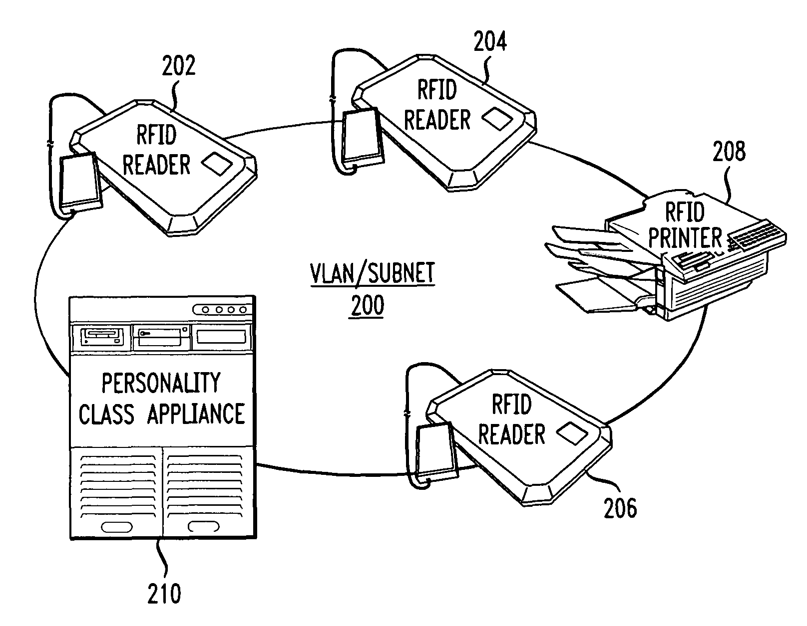
<figref idrefs="DRAWINGS">FIGS. 2A and 2B</figref> are block diagrams showing network connections between RFID devices and a personality class appliance in accordance with one embodiment of the present invention.
<figref idrefs="DRAWINGS">FIG. 3</figref> is a diagram showing the format of an EPC Identity Tag in accordance with one embodiment of the present invention.
<figref idrefs="DRAWINGS">FIG. 4</figref> is a diagram of a Reader with an EPC Identity Tag within the read field in accordance with one embodiment of the present invention.
<figref idrefs="DRAWINGS">FIG. 5</figref> is a block diagram showing components of a personality class appliance in accordance with one embodiment of the present invention.
<figref idrefs="DRAWINGS">FIG. 6</figref> is a flow diagram of a process of preparing for automatic provisioning of a Reader or other device in accordance with one embodiment of the present invention.
<figref idrefs="DRAWINGS">FIG. 7</figref> is a flow diagram showing a process of automatic provisioning of an RFID device in accordance with one embodiment of the present invention.
<figref idrefs="DRAWINGS">FIG. 8</figref> is a block diagram of an RFID network showing middleware servers and related components useful in filtering duplicate messages between Readers and personality class appliances in accordance with one embodiment of the present invention.
<figref idrefs="DRAWINGS">FIG. 9</figref> is a block diagram of a network device that may be configured to implement some methods of the present invention.
DETAILED DESCRIPTION OF THE INVENTION
In this application, numerous specific details are set forth in order to provide a thorough understanding of the present invention. It will be obvious, however, to one skilled in the art, that the present invention may be practiced without some or all of these specific details. In other instances, well known process steps have not been described in detail in order to not obscure the present invention.
Methods and systems for automatically provisioning devices in an RFID network to function in a specific role are described in the accompanying figures. The present invention utilizes a new type or class of Electronic Product Code (“EPC”) Tags, more commonly known as radio frequency identification (“RFID”) Tags, that are attached to or part of a device, such as an RFID Reader. The new type of Tag, referred to as an EPC Identity (“ID”) Tag enables a device to be automatically provisioned to function in a specific role in the RFID network upon the device being booted or powered up. The device sends a data packet via IP multicast protocol (the device being a multicast sender) to a network component referred to as a personality class appliance or PCA (a multicast receiver). The PCA transmits configuration parameters back to the device via a unicast IPmessage. The parameters are used by the device to automatically provision itself. To illustrate a preferred embodiment of the present invention, an RFID Reader is used as an exemplary RFID network device. As used herein, “provisioning” a device can include, but is not limited to, providing network configuration, providing personality configuration, incorporating the device into a network database and enabling the device with software.
<figref idrefs="DRAWINGS">FIGS. 2A and 2B</figref> are block diagrams showing network connections between RFID devices and a PCA in accordance with one embodiment of the present invention. In <figref idrefs="DRAWINGS">FIG. 2A</figref> a virtual LAN (“VLAN”) or subnet <b>200</b> connects RFID Readers <b>202</b>, <b>204</b>, and <b>206</b>, and RFID printer <b>208</b> to a PCA <b>28</b> at a single location. For simplicity, numerous other RFID network devices and components not necessary in describing the present invention such as middleware, application, and DHCP servers, are not shown. PCA <b>28</b> can be on the same VLAN/subnet <b>200</b> as are devices <b>202</b>, <b>204</b>, <b>206</b>, and <b>208</b> or on a separate VLAN/subnet at the same geographic location.
In <figref idrefs="DRAWINGS">FIG. 2B</figref>, the PCA and RFID devices are operating at two separate geographic locations. At Location <b>1</b> a VLAN/subnet <b>212</b> connects various RFID devices <b>214</b>, <b>216</b>, <b>218</b>, and <b>220</b>. A PCA <b>222</b> of the present invention operates at Location <b>2</b>, a separate geographic location. PCA <b>222</b> can be on a VLAN/subnet (not shown) at Location <b>2</b> or can be a stand-alone component. In either case, a wide area network (WAN) or other intermediate network <b>224</b> connects PCA <b>222</b> (or a VLAN on which PCA <b>222</b> operates) to VLAN/subnet <b>200</b> at Location <b>1</b>. WAN or other intermediate network <b>224</b> must be enabled for IP multicasting, reasons for which are described below.
The present invention involves the use of an EPC Tag having a specific role: identifying and containing data about a particular RFID device. Conventional EPC Tags are attached to “things” that traverse a path. For example, in the retail environment, this path may be a supply chain and the thing may be a container of goods or a part in a manufacturing process, and so on. Generally, conventional EPC Tags are affixed to items that are not physical RFID network components, such as Readers, servers, and printers. In contrast the EPC ID Tag of the present invention is affixed or within the read field of a network device, such as a Reader or a printer. <figref idrefs="DRAWINGS">FIG. 3</figref> is a diagram showing the basic structure of an EPC ID Tag of the present invention with random data encodings for illustrative purposes only. EPC ID Tag <b>300</b> shown in <figref idrefs="DRAWINGS">FIG. 3</figref> is a 96-bit Tag. However, many of the concepts described herein can be used in Tags of varying bit length, including 128-bit Tags and 64-bit Tags even though shorter Tags offer less flexibility in terms of how certain fields (e.g., manager, object class) can be populated.
EPCglobal Generation 1 Tag Data Standards Version 1.1 Rev. 1.27 defines the EPCglobal Tag types. More specifically, these standards define how data are encoded on the Tag. The first field is a header <b>302</b>, a fixed 8-bit field. It is unaltered and not utilized in a preferred embodiment of the present invention. Following header <b>302</b> is a 3-bit filter value field <b>304</b>. Of the eight possible binary encodings, four are presently used and four are reserved. The four reserved are 100, 101, 110, and 111. In a preferred embodiment, filter value field <b>304</b> uses one of the reserved encodings to identify a Tag as an EPC ID Tag. In a preferred embodiment, EPCglobal assigns a reserved value, such as 100, for this classification. In another preferred embodiment, an EPCglobal standard is not required given that the EPC ID Tag of the present invention is not intended to traverse the RFID network but rather remain affixed on or within a read field of an RFID device. Following filter value field <b>304</b> are a partition field <b>306</b> (3 bits) and an EPC manager field <b>308</b> (32 bits) which are not relevant to a preferred embodiment of the present invention. Following the EPC manager field <b>308</b> is a variable-length object class field <b>38</b> presently used to classify the Reader. The length of field <b>38</b> is determined by filter value field <b>304</b>. In a preferred embodiment, the value in this field indicates which personality class should be used to provision the Reader. Object class field <b>306</b> is followed by a 32-bit serial number field <b>312</b> used to uniquely identify the device. As described below, the present invention uses the value in field <b>312</b> to make the processes in the PCA and in retrieving personality class configuration parameters possible.
As noted earlier, the EPC ID Tag of the present invention must be positioned within the read field or read point coverage of a Reader whether that be on the Reader, on the Reader antenna, or in proximity of the Reader. <figref idrefs="DRAWINGS">FIG. 4</figref> is a diagram of a Reader with an EPC ID Tag within the read field in accordance with one embodiment of the present invention. RFID Reader <b>400</b> includes one or more RF radios <b>405</b> for transmitting RF waves to, and receiving modulated RF waves from EPC ID Tag <b>440</b> and other RFID Tags. RF radios <b>405</b> provide raw RF data that are converted by an analog-to-digital converter (not shown) and conveyed to other elements of RFID Reader <b>400</b>. In some embodiments, these data are stored, at least temporarily, by CPU <b>48</b> in memory <b>415</b> before being transmitted to other parts of RFID network <b>200</b> via network interface <b>425</b>. Network interface <b>425</b> may be any convenient type of interface, such as an Ethernet interface or IEEE 801.11 A/B/G wireless interface. Also shown is an antenna <b>430</b> for the Reader and an exemplary read field <b>435</b> of the antenna.
Flash memory <b>420</b> is used to store a program (a “bootloader”) for booting/initializing RFID Reader <b>400</b>. The bootloader, which is usually stored in a separate, partitioned area of flash memory <b>420</b>, also allows RFID Reader <b>400</b> to recover from a power loss, etc. In some implementations, flash memory <b>420</b> is used to store personality information and other configuration information obtained from a PCA.
In a preferred embodiment, configuration information is downloaded from a PCA to memory <b>415</b>. Updates may be instigated by the PCA or selected, trusted devices. New versions of the image file (e.g., the running, base image necessary to operate the RFID device) are copied into flash memory <b>420</b>. Alternative embodiments of RFID devices implement methods of the present invention without flash memory <b>420</b>.
More recent RFID devices also include dry contact input/output leads to connect to signal lights, industrial networks or the equivalent. These newer RFID devices typically have evolved in the amount of memory, flash, CPU capacity and methods of determining of the number, type and content of RFID Tags in their field of view. RFID Reader <b>400</b> of the present invention as shown in <figref idrefs="DRAWINGS">FIG. 4</figref> has an EPC ID Tag <b>440</b> in its read field <b>435</b>.
Each Reader in a group of Readers serving the same role in the RFID network share many of the same configuration parameters. Each Reader in the group is in the same personality class. For example, a retail RFID network may require multiple Personality Classes throughout the supply chain, including: receiving operations, shipping operations, low speed conveyors, high speed conveyors, depalletizers/palletizers, and stocking area. A defense or government RFID network would likely have different types of personality classes for its Readers.
The positioning of an EPC ID Tag for a Reader (or a group of Readers) depends on the type of Reader, its antenna configuration, Tag design, and other factors. Depending on the Reader antenna design, the Tag could be physically on the antenna or somewhere nearby. The ability of a Reader to read its associated EPC ID Tag when the Tag is directly attached to the Reader (component <b>400</b> of <figref idrefs="DRAWINGS">FIG. 4</figref>) will depend upon the read point coverage, antenna characteristics, reflection, and other factors. It may also be necessary to attenuate the EPC ID Tag to limit the practical range of the Tag so that it is not read by Readers in close proximity, as described in more detail. As is known in the field of RFID networks, an antenna can be in the same physical box as the Reader or can physically extend from the Reader. In another example, antenna types can be circular or linear. Some basic considerations such as antenna range or read field must be taken into consideration when deploying EPC ID Tags.
It is possible that multiple Readers will have overlapping read point coverage. This is particularly true of dense mode Reader deployments. In such a scenario it may be possible that multiple Readers “see” and “report” the same EPC ID Tag or multiple Tags. One possible solution to this is to attenuate Tags by having Tags with antenna designs that would make the ID Tags more localized to the Reader to which the Tag is associated. Another solution would be to create a binding between a MAC/IP address and an EPC ID Tag and store the binding within the PCA. This could be done via a unicast IP request from the PCA to the Reader after the PCA has learned about the Reader. Another solution is to have middleware servers filter out or delete unintended duplicate reads of the same EPC ID Tag. An RFID network showing middleware servers and related components is shown in <figref idrefs="DRAWINGS">FIG. 8</figref>.
In a preferred embodiment, it is advantageous EPC ID Tag with enough attenuation to limit the read range of the Tag to the intended device. In another embodiment, Readers may have identical functions or roles and have the same exact personalities in which the EPC ID Tag antenna design does not need to be attenuated. However, if there is any difference in personalities of adjacent or tightly grouped Readers the design of the EPC ID Tag antenna is an important factor. With one type of EPC ID Tags, an antenna inlay with a small range is acceptable if the gain on the antenna is configured appropriately. In another embodiment, additional IP multicast sources, such as extra Readers are positioned so that their antennas can read the EPC ID Tags of one or more primary Readers and transmit the data packets to the PCA. The antennas of these extra Readers are dedicated to reading the EPC ID Tags.
In another preferred embodiment, Tags have RF characteristics that render the Tag transmission field relatively local so that the EPC ID Tag will not be inadvertently read by nearby or adjacent Readers for which the Tag is not intended. When a single EPC ID Tag is used to provision a group of Readers, the Tag can be placed in the read field of each Reader in the group. In this embodiment, each Reader in the group transmits the same EPC ID Tag data via IP multicast (discussed below) to one or more PCA, wherein each data packet has the same serial number inherent to the Tag taken from field <b>312</b> of <figref idrefs="DRAWINGS">FIG. 3</figref>. In addition to the automatic provisioning of the Reader, in another preferred embodiment described below, having an EPC ID Tag can be used to conduct regular or random status checks of a Reader or for testing antenna operation through interrogation of the desired multicast receivers, and eliminating excess data traffic on the RFID network.
The present invention utilizes IP multicasting for transmission between Readers and PCAs. IP multicasting is described in detail in RFC2365, incorporated herein in its entirety. In a preferred embodiment of the present invention, a Many to One (“Mt1”) IP multicast implementation is used in which there are many sources (RFID Readers or other network devices) and one receiver (a PCA). Upon detecting an EPC ID Tag, a Reader sources (creates and transmits) an IP multicast packet to a predetermined IPv4/IPv6 Multicast Group Address. The packet uses a destination IP address in the multicast class D address space assigned via the Internet Assigned Numbers Authority (IANA) in the Internetwork Control Block (or the AD-HOC Block). Alternatively the destination IP address may be user assigned from the Administratively Scoped multicast address range as described in RFC2365. The IP Multicast packet, referred to in the present invention as a personality class load request (“PCLR”), contains the EPC ID Tag data, specifically, but not limited to, data in object class field <b>38</b> and serial number field <b>312</b>. The PCLR is transmitted to the PCA using Reader network interface <b>425</b>. In the present invention, the Reader is an IP multicast source. Thus, it does not require an Internet Message Group Protocol (“IGMP”) stack. The PCA is an IP multicast receiver and does require an IGMP stack.
As an IP multicast receiver, the PCA of the present invention is a member of the IP multicast group address that is programmed in the RFID Reader firmware (described below). As is known in the field of IP multicast programming, as an IP multicast receiver, the PCA must have an IGMP host stack. <figref idrefs="DRAWINGS">FIG. 5</figref> is a block diagram showing components of a personality class appliance (PCA) in accordance with one embodiment of the present invention. PCA <b>500</b> has one or more databases <b>502</b> containing one or more tables <b>504</b>. Tables <b>504</b> store mappings between values and personality classes. The values are those found in object class field <b>38</b>. The personality classes are comprised of configuration parameters, which are stored in tables <b>504</b>. For example, a value of “7” in object class field <b>38</b> maps to configuration parameter <b>1</b>, parameter <b>2</b>, and so on, which collectively make up a personality class. The values can be customized by an end user and personality classes can be added or deleted as necessary.
Upon receipt of a PCLR data packet from a Reader, PCA <b>500</b> deciphers the object class field value and then references tables <b>504</b> for a match. The personality class contains the configuration parameters necessary for the Reader to assume its unique role and specific function within the RFID network. If there is no match between the value in the PCLR and in tables <b>504</b>, in a preferred embodiment a user-defined default personality class be assigned to the Reader. In another embodiment, the PCLR is discarded and an error message is returned.
When a Reader is damaged, lost, inoperable, or fails during operation, it is replaced with a different Reader. When the new Reader boots up, it repeats the process described above. The PCLR that is transmitted from the new Reader via IP multicast simply contains a different serial number. The EPC ID Tag from the previous Reader may or may not be used in conjunction with the replacement Reader. In the case where the same EPC ID Tag is reused to provision the replacement Reader, no changes are made to the PCA, unless the PCA has been configured to maintain state between device specific parameters (e.g., hostname, IP address, MAC address, etc.). In such a case the PCA will update its state tables to reflect any changes between the new and old Reader. In a scenario when the original EPC ID Tag cannot be reused for the replacement Reader, due to the condition, location, placement of the Tag, then the PCA will assign new personality parameters to the Reader and maintain state of the old Reader EPC ID Tag for a predefined, user configurable interval.
In another preferred embodiment, all potential personality class types are defined and made a standard in the RFID industry. This would ensure that all implementations of PCA <b>500</b> are uniform. In a preferred embodiment, PCA <b>500</b> is a server running the necessary applications to provide the functionality described herein, or a network application appliance such as an Application Oriented Network (“AON”) Module from Cisco Systems, Inc. of San Jose, Calif., configured to perform the same tasks. The capabilities of PCA <b>500</b> will vary depending upon the level of functionality required by the RFID network implementation.
In another preferred embodiment, redundancy can be achieved by adding a second PCA. In this embodiment, a Reader can transmit its PCLR via multicast to a group of two or more PCAs and whichever PCA is enabled and listening can respond. In another embodiment, there is a master/slave relationship among PCAs using existing protocols such as HSRP, VRRP, or GLBP. In this embodiment, it is necessary to maintain PCA database state across multiple PCAs when deployed in a redundant manner.
Once a Reader receives the unicast data packet from the PCA, personality class configuration parameters are verified through an application layer acknowledgement. The Reader stops repeatedly sending PCLR packets to the PCA once the personality class configuration has been verified by the Reader. In the event of a failed personality class parameter load, the Reader would re-start sending PCLR packets to the PCA.
<figref idrefs="DRAWINGS">FIG. 6</figref> is a flow diagram of a process of preparing for automatic provisioning of a Reader or other device in accordance with one embodiment of the present invention. At step <b>602</b>, the entity operating the RFID network prepares the PCA by registering for an IP Multicast Group Address space with IANA. Once an IP multicast address space has been designated, at step <b>604</b> firmware in the Readers is updated. This includes inputting the IP multicast address. The Reader firmware is also updated so that when the Reader reads an EPC Tag and detects a value in filter value field <b>304</b>, one of: 100, 101, 110, or 111, whether by EPC Global standard or by entity-imposed or entity-regulated mandate, the Reader knows that the Tag is an EPC Identity Tag. At step <b>606</b> the entity operating the RFID network configures the Readers' antennas. At step <b>608</b> the entity ensures that the EPC ID Tag is in the read field of the intended Reader and out of the read fields of nearby Readers or devices. At step <b>608</b> the RFID network is IP multicast enabled thereby ensuring that the PCA receives data packets regardless of the PCA's location. Part of this step is ensuring that the PCA is subscribed to a designated IP Multicast Group Address. This allows the PCA to receive PCLRs from the Readers.
<figref idrefs="DRAWINGS">FIG. 7</figref> is a flow diagram showing a process of automatic provisioning of an RFID device in accordance with one embodiment of the present invention. The process described in <figref idrefs="DRAWINGS">FIG. 7</figref> takes place after the steps described in <figref idrefs="DRAWINGS">FIG. 6</figref> and a PCA has been installed as part of the RFID network and connectivity has been established.
At step <b>702</b> a Reader or other RFID device boots up and initializes its antenna source. The Reader comes up like any other device, such as a PC, printer, etc. and has network parameters such as IP address and default gateway obtained through DHCP. At step <b>704</b> the Reader detects a Tag in its read field and in the Tag sees a filter field value which has been pre-designated for identifying the Tag as an EPC Identity Tag of the present invention. At step <b>706</b> the Reader prepares to transmit an IP multicast message, a PCLR, to the PCA. The IP multicast address of the PCA is stored in the Reader firmware.
At step <b>708</b> the Reader sources the PCLR containing EPC ID Tag data and the Reader's IP address to the PCA. It is worth noting that the MAC address, host name, and other parameters of the Reader are not needed and are irrelevant in preparing the data packet and transmitting the PCLR. However, in some embodiments, these parameters are stored (their state is maintained) after a device has been provisioned.
At step <b>708</b> the PCA receives the data packet via IP multicast from the Reader. At step <b>712</b> the PCA examines the EPC ID Tag data in the packet. From the value in the object class field transmitted in the data packet, the PCA determines the personality class that it needs to retrieve from its databases and tables as shown in <figref idrefs="DRAWINGS">FIG. 5</figref>. For example, a value of “6” in the object class field may correspond to a “High Speed Conveyor” personality class and a corresponding set of parameters that will be used to configure the Reader. The PCA also reads the serial number contained in the data packet and may use it to retrieve configuration parameters it has cached. If the PCA has seen a serial number before, it can retrieve the personality configuration parameters from its databases or from a source accessible to the PCA.
At step <b>714</b> the PCA sends configuration parameters back to the Reader via a unicast IP message. The IP address of the Reader is sourced in the data packet the PCA received from the Reader. At step <b>716</b> the Reader receives the unicast data packet containing the configuration parameters which it uses to configure itself.
Once a Reader receives configuration parameters at step <b>716</b> via a unicast message from a PCA, the Reader sends an acknowledgement (“ACK”) packet to the PCA at step <b>718</b> at which stage the process is complete. An ACK message prevents the PCA from repeatedly sending the personality class configuration parameters to the Reader. Transmission of an ACK message from the Reader is enabled by modifying the application layer of the Reader's firmware to require that an ACK message be sent once it receives configuration parameter. In another embodiment, the ACK message requirement can be hard-coded into the Reader firmware. A hard-coded parameter can be user configurable and be adjusted depending on several factors such as load attributes of the Reader, whether fast or slow convergence (the speed at which devices are activated) is desired. This can prevent overloading PCA(s) with traffic. This is particularly useful when the PCA sends personality data in multiple packets to a group of Readers, thereby allowing the PCA to confirm that each Reader associated with the group antenna source/Reader has received the personality class data. However the ACK message is implemented, this requirement or feature is one option for making the automatic provisioning methodology of the present invention a stateful system. In another embodiment, is a flag in the Reader firmware signifies that the Reader's personality has been loaded. At this stage the automatic provisioning process is complete.
Those of skill in the art will appreciate that the method steps discussed in <figref idrefs="DRAWINGS">FIGS. 6 and 7</figref> need not be performed (and in some implementations are not performed) in the order shown and described. Moreover, some implementations of the methods discussed herein may include more or fewer steps than those shown in <figref idrefs="DRAWINGS">FIGS. 6 and 7</figref>.
As described above, Readers can be divided into several specific groups at a certain location where each group maps to a personality class. For example, in a retail environment, Readers at a dock door can be in one group. In this embodiment, the PCA sends signals to the group of Readers. A response from the group is unicast to the PCA. Possible uses of this configuration include, but are not limited to: management of the device; simultaneous modification of parameters of all devices in a group; shutdown of specific functions; status checks; forcing reloads; failover to another Reader in the group; and providing heartbeats.
After a group of Readers has been provisioned, if there is a change to the group, a system administrator can invoke a modification to the PCA to implement the change to the group of Readers (via CLI, remote access, etc.). The PCA multicasts the change or set of change commands to the Readers of the target group. This post-provisioning propagation eliminates the need to repeatedly make the change for each Reader in the group. EPC ID Tags can also be used to perform Reader health checks, for example, the ability to determine operational read points (antennas), validate Tag read operations, filter testing, etc. given that the EPC ID Tag is always intended to be within the read field of the Reader. This enables a sensory RFID network.
In another preferred embodiment, the Reader or other RFID device implements its own native IP multicast thereby making the Reader a multicast receiver. In this embodiment, the RFID Reader joins an IP Multicast Address group derived from its EPC ID Tag and has an IGMP host stack. Thus, the PCA is a multicast sender and the Reader is a multicast receiver. The personality class parameters transmitted from the PCA to the Reader are streamed to the Reader via PGM or another suitable error correcting method. The method uses the same EPC ID Tag procedure described above, except that the PCA derives a destination IP multicast group by converting a value in object class field <b>308</b> to the Reader's IP multicast group address. Object class field bits are mapped to multicast addresses. Bits in the object class field are still used to determine the Reader's personality class and the personality class' associated IP Multicast Group address. In an IPv4 implementation the first two octets of the 32-bit IP address are fixed and the remaining two octets can be obtained by using 16 bits from the object class field. There is more flexibility with the 96-bit EPC Tags since the Object Class field is a variable length field.
In another preferred embodiment of the present invention, the boot up of multiple Readers at the same time is pre-set with a rate limit. A rate limit is useful, for example, at a facility with a high number of Readers (e.g., 35) and other RFID devices that simultaneously power up. Without a rate limit in such scenarios, a PCA can be overloaded with multicast messages hitting it at the same time thereby potentially disabling the PCA from further operation or causing errors in personality class transmissions. One method of establishing a rate limit is to modify the firmware in the Readers and devices to enforce pacing by regulating time intervals between message, for example, by using a pseudo random value from the system clock. Another way to avoid overloading the PCA is to have one EPC ID Tag for a group of Readers as described above.
<figref idrefs="DRAWINGS">FIG. 8</figref> illustrates another portion of a simplified RFID network <b>800</b> showing middleware servers and other components that can be used to filter our or delete duplicate reads of the same EPC ID Tag resulting from dense mode Reader deployments or where read point coverage may intersect. The details of network <b>800</b> are purely illustrative. Application server <b>805</b> operates according to instructions from application software <b>810</b> that resides in a memory device of, or accessible to, application server <b>805</b>. Application server <b>805</b> is in communication with middleware servers <b>815</b> and <b>820</b> of site <b>825</b>, via a virtual local area network (“VLAN2”) <b>830</b> in this example. In this example, at least one of middleware servers <b>870</b> and <b>880</b> is a standby middleware server.
Site <b>825</b>, for example a warehouse, includes numerous locations at which RFID devices are deployed. One such location is door <b>835</b>, where a plurality of RFID devices <b>840</b> are positioned.
RFID devices <b>840</b> are in communication with metaserver <b>845</b> via “VLAN0” <b>842</b>. In some preferred implementations metaserver <b>845</b> includes servers and associated devices that provide various functions, including those of DHCP server <b>863</b>, assigner <b>853</b> and registrar <b>860</b>. Accordingly, some of the functionality provided by the registrar and assigner as described in the Cross-Referenced Applications will be performed by metaserver <b>845</b>. In some implementations, metaserver <b>845</b> is a single device and in other implementations metaserver <b>845</b> is an association of separate physical devices. Metaserver <b>845</b> may also include a load balancer. Middleware servers <b>815</b>, <b>820</b>, <b>870</b> and <b>880</b> can communicate with metaserver <b>845</b> and registrar <b>860</b> via “VLAN1” <b>850</b>.
<figref idrefs="DRAWINGS">FIG. 5</figref> described above showed software and data components of a PCA of the present invention. <figref idrefs="DRAWINGS">FIG. 9</figref> is a block diagram showing the internal hardware components of a PCA or equivalent network device that may be configured to implement some methods and portions of methods of the present invention. Network device <b>960</b> includes a master central processing unit (CPU) <b>962</b>, interfaces <b>968</b>, and a bus <b>967</b> (e.g., a PCI bus). Generally, interfaces <b>968</b> include ports <b>969</b> appropriate for communication with the appropriate media. In some embodiments, one or more of interfaces <b>968</b> includes at least one independent processor <b>974</b> and, in some instances, volatile RAM. Independent processors <b>974</b> may be, for example ASICs or any other appropriate processors. According to some such embodiments, these independent processors <b>974</b> perform at least some of the functions of the logic described herein. In some embodiments, one or more of interfaces <b>968</b> control such communications-intensive tasks as media control and management. By providing separate processors for the communications-intensive tasks, interfaces <b>968</b> allow the master microprocessor <b>962</b> efficiently to perform other functions such as routing computations, network diagnostics, security functions, etc.
The interfaces <b>968</b> are typically provided as interface cards (sometimes referred to as “line cards”). Generally, interfaces <b>968</b> control the sending and receiving of data packets over the network and sometimes support other peripherals used with the network device <b>960</b>.
When acting under the control of appropriate software or firmware, in some implementations of the invention CPU <b>962</b> may be responsible for implementing specific functions associated with the functions of a desired network device, such as an RFID Reader. According to some embodiments, CPU <b>962</b> accomplishes all these functions under the control of software including an operating system (e.g. Linux, VxWorks, etc.), and any appropriate applications software.
CPU <b>962</b> may include one or more processors <b>963</b> such as a processor from the Motorola family of microprocessors or the MIPS family of microprocessors. In an alternative embodiment, processor <b>963</b> is specially designed hardware for controlling the operations of network device <b>960</b>. In a specific embodiment, a memory <b>961</b> (such as non-volatile RAM and/or ROM) also forms part of CPU <b>962</b>. However, there are many different ways in which memory could be coupled to the system. Memory block <b>961</b> may be used for a variety of purposes such as, for example, caching and/or storing data, programming instructions, etc.
Regardless of network device's configuration, it may employ one or more memories or memory modules (such as, for example, memory block <b>965</b>) configured to store data, program instructions for the general-purpose network operations and/or other information relating to the functionality of the techniques described herein. The program instructions may control the operation of an operating system and/or one or more applications, for example.
Because such information and program instructions may be employed to implement the systems/methods described herein, the present invention relates to machine-readable media that include program instructions, state information, etc. for performing various operations described herein. Examples of machine-readable media include, but are not limited to, magnetic media such as hard disks, floppy disks, and magnetic tape; optical media such as CD-ROM disks; magneto-optical media; and hardware devices that are specially configured to store and perform program instructions, such as read-only memory devices (ROM) and random access memory (RAM). The invention may also be embodied in a carrier wave traveling over an appropriate medium such as airwaves, optical lines, electric lines, etc. Examples of program instructions include both machine code, such as produced by a compiler, and files containing higher level code that may be executed by the computer using an interpreter.
Although the system shown in <figref idrefs="DRAWINGS">FIG. 9</figref> illustrates one specific network device of the present invention, it is by no means the only network device architecture on which the present invention can be implemented. For example, an architecture having a single processor that handles communications as well as routing computations, etc. is often used. Further, other types of interfaces and media could also be used with the network device. The communication path between interfaces/line cards may be bus based (as shown in <figref idrefs="DRAWINGS">FIG. 9</figref>) or switch fabric based (such as a cross-bar).
Although the present invention involves methods and devices for automatically provisioning devices in an RFID network, many aspects of the present invention can be applied to identifying and provisioning devices, including wireless and wired devices, in other types of networks. For example, the present invention may also be used for automatically provisioning manufacturing devices, networked sensor devices, IP phones and hand-held devices, portable digital assistants and related network devices, such as servers and switches. Similarly, although much of the discussion herein applies to implementations using 64-Bit and 96-Bit EPC Tag structures and the IP multicasting protocol, the present invention is not necessarily protocol or format specific and may be used, for example, in implementations using IP broadcasting and 128-Bit EPC Tags. Likewise, while the implementations described herein refer to exemplary EPC Tag fields, other fields and specific bits within those fields may advantageously be used to implement the present invention.
The methods and devices of the present invention have broad utility, both in the public and private sectors. Any enterprise that needs to keep track of how its equipment or goods are being deployed, whether that equipment is used for commercial purposes, for military purposes, etc. can benefit from an RFID network. RFID devices that are networked according to the present invention can provide information allowing enterprises to track equipment and products (or groups of products). The information provided by RFID devices that are networked according to the present invention will be of great benefit for enterprise resource planning, including the planning of manufacturing, distribution, sales and marketing.
Although illustrative embodiments and applications of this invention are shown and described herein, many variations and modifications are possible which remain within the concept, scope, and spirit of the invention, and these variations would become clear to those of ordinary skill in the art after perusal of this application. Accordingly, the embodiments described are to be considered as illustrative and not restrictive, and the invention is not to be limited to the details given herein, but may be modified within the scope and equivalents of the appended claims.
Contents5
10 sheets
Sheet 1 Sheet 2 Sheet 3 Sheet 4 Sheet 5 Sheet 6 Sheet 7 Sheet 8 Sheet 9 Sheet 10
Every citation, both waysCites: the store holds 108 of 109
| Document | Relation | Office | Cited during |
|---|---|---|---|
| US2016078259A1 | Cited by | United States of America | Pre-grant |
| US9357340B2 | Cited by | United States of America | Search report |
| US2013214899A1 | Cited by | United States of America | Pre-grant |
| US9182748B2 | Cited by | United States of America | Search report |
| US11213773B2 | Cited by | United States of America | Applicant |
| US12014240B2 | Cited by | United States of America | Applicant |
| US9064164B2 | Cited by | United States of America | Search report |
| US2014111308A1 | Cited by | United States of America | Pre-grant |
| US2015296398A1 | Cited by | United States of America | Pre-grant |
| US12387062B2 | Cited by | United States of America | Applicant |
| US9294954B2 | Cited by | United States of America | Search report |
| US2015326999A1 | Cited by | United States of America | Pre-grant |
| US11244126B2 | Cited by | United States of America | Applicant |
| US11727225B2 | Cited by | United States of America | Applicant |
| US2001012292A1 | Cites | United States of America | Applicant |
| US2001028308A1 | Cites | United States of America | Applicant |
| US2001056504A1 | Cites | United States of America | Applicant |
| US2002001307A1 | Cites | United States of America | Applicant |
| US2002016739A1 | Cites | United States of America | Applicant |
| US2002046263A1 | Cites | United States of America | Applicant |
| US2002075805A1 | Cites | United States of America | Applicant |
| US2002136403A1 | Cites | United States of America | Applicant |
| US2002141393A1 | Cites | United States of America | Applicant |
| US2002161907A1 | Cites | United States of America | Applicant |
| US2003014665A1 | Cites | United States of America | Applicant |
| US2003046339A1 | Cites | United States of America | Applicant |
| US2003065784A1 | Cites | United States of America | Applicant |
| US2003084279A1 | Cites | United States of America | Applicant |
| US2003095032A1 | Cites | United States of America | Search report |
| US2003126248A1 | Cites | United States of America | Applicant |
| US2003174714A1 | Cites | United States of America | Applicant |
| US2003177374A1 | Cites | United States of America | Applicant |
| US2003226887A1 | Cites | United States of America | Search report |
| US2004010594A1 | Cites | United States of America | Applicant |
| US2004021569A1 | Cites | United States of America | Applicant |
| US2004061646A1 | Cites | United States of America | Applicant |
| US2004064577A1 | Cites | United States of America | Applicant |
| US2004069852A1 | Cites | United States of America | Applicant |
| US2004073600A1 | Cites | United States of America | Applicant |
| US2004100383A1 | Cites | United States of America | Applicant |
| US2004108795A1 | Cites | United States of America | Applicant |
| US2004128389A1 | Cites | United States of America | Applicant |
| US2004145474A1 | Cites | United States of America | Applicant |
| US2004257202A1 | Cites | United States of America | Applicant |
| US2004259557A1 | Cites | United States of America | Applicant |
| US2005027778A1 | Cites | United States of America | Applicant |
| US2005060208A1 | Cites | United States of America | Applicant |
| US2005080881A1 | Cites | United States of America | Applicant |
| US2005088284A1 | Cites | United States of America | Applicant |
| US2005093679A1 | Cites | United States of America | Applicant |
| US2005099270A1 | Cites | United States of America | Applicant |
| US2005102406A1 | Cites | United States of America | Applicant |
| US2005198228A1 | Cites | United States of America | Applicant |
| US2005199716A1 | Cites | United States of America | Applicant |
| US2005209947A1 | Cites | United States of America | Applicant |
| US2005228887A1 | Cites | United States of America | Applicant |
| US2005252957A1 | Cites | United States of America | Applicant |
| US2005252970A1 | Cites | United States of America | Applicant |
| US2005252971A1 | Cites | United States of America | Applicant |
| US2005253717A1 | Cites | United States of America | Applicant |
| US2005253718A1 | Cites | United States of America | Applicant |
| US2005253722A1 | Cites | United States of America | Applicant |
| US2006072497A1 | Cites | United States of America | Search report |
| US4625081A | Cites | United States of America | Applicant |
| US4688026A | Cites | United States of America | Applicant |
| US5339073A | Cites | United States of America | Applicant |
| US5588009A | Cites | United States of America | Applicant |
| US5646616A | Cites | United States of America | Applicant |
| US5850187A | Cites | United States of America | Applicant |
| US5887176A | Cites | United States of America | Applicant |
| US6070187A | Cites | United States of America | Applicant |
| US6073178A | Cites | United States of America | Applicant |
| US6111517A | Cites | United States of America | Applicant |
| US6115079A | Cites | United States of America | Applicant |
| US6212563B1 | Cites | United States of America | Applicant |
| US6272113B1 | Cites | United States of America | Applicant |
| US6282186B1 | Cites | United States of America | Applicant |
| US6300903B1 | Cites | United States of America | Applicant |
| US6324575B1 | Cites | United States of America | Applicant |
| US6330597B2 | Cites | United States of America | Applicant |
| US6381465B1 | Cites | United States of America | Applicant |
| US6393458B1 | Cites | United States of America | Applicant |
| US6473858B1 | Cites | United States of America | Applicant |
| US6539281B2 | Cites | United States of America | Applicant |
| US6553489B1 | Cites | United States of America | Applicant |
| US6677852B1 | Cites | United States of America | Applicant |
| US6832249B2 | Cites | United States of America | Applicant |
| US6836778B2 | Cites | United States of America | Applicant |
| US6843121B1 | Cites | United States of America | Applicant |
| US6912213B2 | Cites | United States of America | Applicant |
| US6963282B1 | Cites | United States of America | Applicant |
| US6995655B2 | Cites | United States of America | Applicant |
| US7064660B2 | Cites | United States of America | Applicant |
| US7065086B2 | Cites | United States of America | Applicant |
| US7075412B1 | Cites | United States of America | Search report |
| US7103040B2 | Cites | United States of America | Applicant |
| US7117364B1 | Cites | United States of America | Applicant |
| US7150017B1 | Cites | United States of America | Applicant |
| US7165722B2 | Cites | United States of America | Search report |
| US7177915B2 | Cites | United States of America | Applicant |
4 members in 1 office
Priority claims6
| Document | Office | Kind | Date |
|---|---|---|---|
| 73708805 | United States of America | P | |
| 73708805 | United States of America | P | |
| 34673906 | United States of America | A | |
| 60737088 | – | – | – |
| US20050737088P | – | – | – |
| US20060346739 | – | – | – |
Members4
| Document | Office | Kind | |
|---|---|---|---|
| US2007109100A1 | United States of America | A1 | |
| US8698603B2This record | United States of America | B2 | |
| US2014111308A1 | United States of America | A1 | |
| US9064164B2 | United States of America | B2 |
98 transactions on the USPTO file
Allowed after 2 non-final rejections, 1 final rejection and 2 RCEs.
- Non-final rejections
- 2
- Final rejections
- 1
- RCEs
- 2
- Appeals
- 0
Over time
Point at a mark for the transactionTransactions
| Event | Code | |
|---|---|---|
| Payment of Maintenance Fee, 8th Year, Large EntityM1552 | M1552 | |
| Email NotificationEML_NTR | EML_NTR | |
| Change in Power of Attorney (May Include Associate POA)PA.. | PA.. | |
| Correspondence Address ChangeC.AD | C.AD | |
| Payment of Maintenance Fee, 4th Year, Large EntityM1551 | M1551 | |
| Recordation of Patent Grant MailedPGM/ | PGM/ | |
| Patent Issue Date Used in PTA CalculationAllowedPTAC | PTAC | |
| Email NotificationEML_NTR | EML_NTR | |
| Issue Notification MailedAllowedWPIR | WPIR | |
| Dispatch to FDCD1935 | D1935 | |
| Application Is Considered Ready for IssuePILS | PILS | |
| Issue Fee Payment VerifiedN084 | N084 | |
| Issue Fee Payment ReceivedIFEE | IFEE | |
| Correspondence Address ChangeC.ADB | C.ADB | |
| Correspondence Address ChangeC.ADB | C.ADB | |
| Mail Notice of AllowanceAllowedMN/=. | MN/=. | |
| Notice of Allowance Data Verification CompletedAllowedN/=. | N/=. | |
| Examiner's Amendment CommunicationEX.A | EX.A | |
| Change in Power of Attorney (May Include Associate POA)PA.. | PA.. | |
| Correspondence Address ChangeC.AD | C.AD | |
| Disposal for a RCE / CPA / R129AbandonedABN9 | ABN9 | |
| Information Disclosure Statement consideredIDSC | IDSC | |
| Information Disclosure Statement consideredIDSC | IDSC | |
| Information Disclosure Statement consideredIDSC | IDSC | |
| Information Disclosure Statement consideredIDSC | IDSC | |
| Information Disclosure Statement consideredIDSC | IDSC | |
| Information Disclosure Statement consideredIDSC | IDSC | |
| Information Disclosure Statement (IDS) FiledWIDS | WIDS | |
| Information Disclosure Statement (IDS) FiledWIDS | WIDS | |
| Information Disclosure Statement (IDS) FiledWIDS | WIDS | |
| Information Disclosure Statement (IDS) FiledWIDS | WIDS | |
| Reference capture on IDSRCAP | RCAP | |
| Information Disclosure Statement (IDS) FiledM844 | M844 | |
| Request for Continued Examination (RCE)RCEX | RCEX | |
| Information Disclosure Statement (IDS) FiledWIDS | WIDS | |
| Information Disclosure Statement (IDS) FiledWIDS | WIDS | |
| Workflow - Request for RCE - BeginBRCE | BRCE | |
| Electronic ReviewELC_RVW | ELC_RVW | |
| Email NotificationEML_NTF | EML_NTF | |
| Mail Notice of AllowanceAllowedMN/=. | MN/=. | |
| Notice of Allowance Data Verification CompletedAllowedN/=. | N/=. | |
| Examiner's Amendment CommunicationEX.A | EX.A | |
| Date Forwarded to ExaminerFWDX | FWDX | |
| Information Disclosure Statement consideredIDSC | IDSC | |
| Reference capture on IDSRCAP | RCAP | |
| Information Disclosure Statement (IDS) FiledM844 | M844 | |
| Response after Non-Final ActionA... | A... | |
| Information Disclosure Statement (IDS) FiledWIDS | WIDS | |
| Electronic ReviewELC_RVW | ELC_RVW | |
| Email NotificationEML_NTF | EML_NTF | |
| Mail Non-Final RejectionNon-final rejectionMCTNF | MCTNF | |
| Non-Final RejectionNon-final rejectionCTNF | CTNF | |
| Date Forwarded to ExaminerFWDX | FWDX | |
| Supplemental ResponseSA.. | SA.. | |
| Information Disclosure Statement consideredIDSC | IDSC | |
| Reference capture on IDSRCAP | RCAP | |
| Information Disclosure Statement (IDS) FiledM844 | M844 | |
| Information Disclosure Statement (IDS) FiledWIDS | WIDS | |
| Correspondence Address ChangeC.ADB | C.ADB | |
| Information Disclosure Statement consideredIDSC | IDSC | |
| Information Disclosure Statement (IDS) FiledM844 | M844 | |
| Information Disclosure Statement (IDS) FiledM844 | M844 | |
| Information Disclosure Statement (IDS) FiledWIDS | WIDS | |
| Information Disclosure Statement consideredIDSC | IDSC | |
| Information Disclosure Statement (IDS) FiledM844 | M844 | |
| Information Disclosure Statement (IDS) FiledWIDS | WIDS | |
| Date Forwarded to ExaminerFWDX | FWDX | |
| Request for Continued Examination (RCE)RCEX | RCEX | |
| Disposal for a RCE / CPA / R129AbandonedABN9 | ABN9 | |
| Workflow - Request for RCE - BeginBRCE | BRCE | |
| Electronic ReviewELC_RVW | ELC_RVW | |
| Email NotificationEML_NTF | EML_NTF | |
| Mail Final Rejection (PTOL - 326)Final rejectionMCTFR | MCTFR | |
| Final RejectionFinal rejectionCTFR | CTFR | |
| Date Forwarded to ExaminerFWDX | FWDX | |
| Response after Non-Final ActionA... | A... | |
| Electronic ReviewELC_RVW | ELC_RVW | |
| Email NotificationEML_NTF | EML_NTF | |
| Mail Non-Final RejectionNon-final rejectionMCTNF | MCTNF | |
| Non-Final RejectionNon-final rejectionCTNF | CTNF | |
| Case Docketed to Examiner in GAUDOCK | DOCK | |
| Electronic Information Disclosure StatementEIDS. | EIDS. | |
| Information Disclosure Statement consideredIDSC | IDSC | |
| Information Disclosure Statement (IDS) FiledWIDS | WIDS | |
| Withdraw Flagged for 5/25W525 | W525 | |
| Flagged for 5/25F525 | F525 | |
| Case Docketed to Examiner in GAUDOCK | DOCK | |
| PG-Pub Issue NotificationPG-ISSUE | PG-ISSUE | |
| Oath or Declaration Filed (Including Supplemental)C602 | C602 | |
| Preliminary AmendmentA.PE | A.PE | |
| IFW TSS Processing by Tech Center CompleteTSSCOMP | TSSCOMP | |
| Case Docketed to Examiner in GAUDOCK | DOCK | |
| Application Dispatched from OIPEOIPE | OIPE | |
| Application Is Now CompleteCOMP | COMP | |
| Cleared by L&R (LARS)L128 | L128 | |
| Referred to Level 2 (LARS) by OIPE CSRL198 | L198 | |
| IFW Scan & PACR Auto Security ReviewSCAN | SCAN | |
| Initial Exam Team nnIEXX | IEXX |
6 legal events, as the office reported them to INPADOC
Over the term
Point at a mark for the eventEvents
| Event | Code | |
|---|---|---|
| Maintenance fee paymentMAFP | MAFP | |
| Maintenance fee paymentMAFP | MAFP | |
| Maintenance fee paymentMAFP | MAFP | |
| Information on status: patent grantGrantedPATENTED CASESTCF | STCF | |
| AssignmentAS | AS | |
| AssignmentAS | AS |
Numbers
- Publication
- 08698603
- Publication, DOCDB
- 8698603
- Publication, EPODOC
- US8698603
- Application
- 11346739
- Application, DOCDB
- 34673906
- Application, EPODOC
- US20060346739
Titles
- English
- Methods and systems for automatic device provisioning in an RFID network using IP multicast
Patent term adjustment
- A delay
- +1,747 daysthe office missed an examination deadline
- B delay
- +525 dayspendency past three years
- Overlap
- −241 daysdelays counted once
- Applicant delay
- −5 days
- Net adjustment
- 2,026 days
Classification
- CPC, 2
- G06K7/10366
- H04L12/189
- IPC, 1
- H04Q3 00
- USPC, 7
- 340010400
- 235375000
- 235385000
- 340010410
- 340010510
- 370352000
- 370465000