Improved harness for breathing apparatus
Abstract
The invention relates to the modified device for respirator, comprising: aThe structure supporting part (10), wherein for holding the front bottle and to the clothes back, and left and right. The left shoulder belt (110) and left shoulder belt (120) are right are towards the supporting structure left component, and each shoulder belt is connected to the structure support part is first end and connected with the supporting structure component lower part of the second. The flexible sleeve tubes (140) and (150) extends from the supporting structure component lower part of the structure supporting part, the flexible tube face at a position of the left shoulder belt or the left shoulder belt. The Daocao (30) and guide groove (32) arranged longitudinally along the structure supporting part, and extending along the left, to be used to form with the flexible catheter.
Term
3.6 yearsto projected expiry
Projected expiry 5 May 2030, counted from filing; an application has no term until it is granted.
- Priority
- Filed
- Published
- Today
- Projected expiry
15 claims: 3 independent, 12 dependent
- 1A device for a respirator, comprising:a structural support member, which has a front surface for accommodating a gas cylinder and a back surface for facing the back of the wearer, as well as left and right sides;left and right shoulder straps, so The left shoulder belt and the right shoulder belt are respectively arranged toward the left and right sides of the structural support member, and each shoulder belt has a first end connected to the upper part of the structural support member and a first end connected to the structural support member. The second end of the lower part;a plurality of flexible conduits extending from the lower part of the structural support member along the structural support member, each flexible conduit extending to a position on the left or right shoulder strap;and The left guide groove and the right guide groove, the left guide groove and the right guide groove extend longitudinally along the structural support member and along the left and right sides, respectively, for accommodating the flexible conduit;wherein, the At least one of the left guide groove and the right guide groove is arranged to accommodate at least two flexible conduits. 1. 一种用于呼吸器的装具,包括: 结构支撑部件,其具有用于容纳气瓶的正面和用于面向穿戴者后背的背面,以及左侧 和右侧; 左肩带和右肩带,所述左肩带和右肩带分别朝着所述结构支撑部件的左侧和右侧排 列,每个肩带具有连接到所述结构支撑部件的上部的第一端和连接到所述结构支撑部件的 下部的第二端; 多个柔性导管,其从所述结构支撑部件的下部沿着所述结构支撑部件延伸,每个柔性 导管都延伸到所述左肩带或右肩带上的一个位置;以及 左导槽和右导槽,所述左导槽和右导槽纵向地沿着所述结构支撑部件并分别沿着左侧 和右侧延伸,以用于容纳所述柔性导管; 其中,所述左导槽和右导槽中的至少一个被安排成容纳至少两个柔性导管。
- 4A device for a respirator, comprising:a structural support member, which has a front surface for accommodating a gas cylinder and a back surface for facing the back of the wearer, as well as left and right sides;left and right shoulder straps, so The left shoulder belt and the right shoulder belt are respectively arranged toward the left and right sides of the structural support member, and each shoulder belt has a first end connected to the upper part of the structural support member and a first end connected to the structural support member. The second end of the lower part;a plurality of flexible conduits extending from the lower part of the structural support member along the structural support member, each flexible conduit extending to a position on the left or right shoulder strap;left A guide groove and a right guide groove, the left guide groove and the right guide groove extending longitudinally along the structural support member and along the left and right sides, respectively, for accommodating the flexible conduit;and a transverse guide groove, It extends laterally through the upper region of the structural support member from one side to the other for accommodating at least one flexible conduit;wherein, the lateral guide groove has a first guide near the upper end of the left guide groove End, and the second end close to the upper end of the right guide groove. 4. 一种用于呼吸器的装具,包括: 结构支撑部件,其具有用于容纳气瓶的正面和用于面向穿戴者后背的背面,以及左侧 和右侧; 左肩带和右肩带,所述左肩带和右肩带分别朝着所述结构支撑部件的左侧和右侧排 列,每个肩带具有连接到所述结构支撑部件的上部的第一端和连接到所述结构支撑部件的 下部的第二端; 多个柔性导管,其从所述结构支撑部件的下部沿着所述结构支撑部件延伸,每个柔性 导管都延伸到所述左肩带或右肩带上的一个位置; 左导槽和右导槽,所述左导槽和右导槽纵向地沿着所述结构支撑部件并分别沿着左侧 和右侧延伸,以用于容纳所述柔性导管;以及 横向导槽,其从一侧到另一侧横向地延伸穿过所述结构支撑部件的上部区域,以用于 容纳至少一个柔性导管; 其中,所述横向导槽具有靠近所述左导槽的上端的第一端,和靠近所述右导槽的上端 的第二端。
- 1517. A device for respirators is essentially as described in the drawings. 17. 一种用于呼吸器的装具,实质上是如此处关于附图所描述的。
Independent claims3
54 paragraphs, as filed
Improved equipment for breathing apparatus technical field
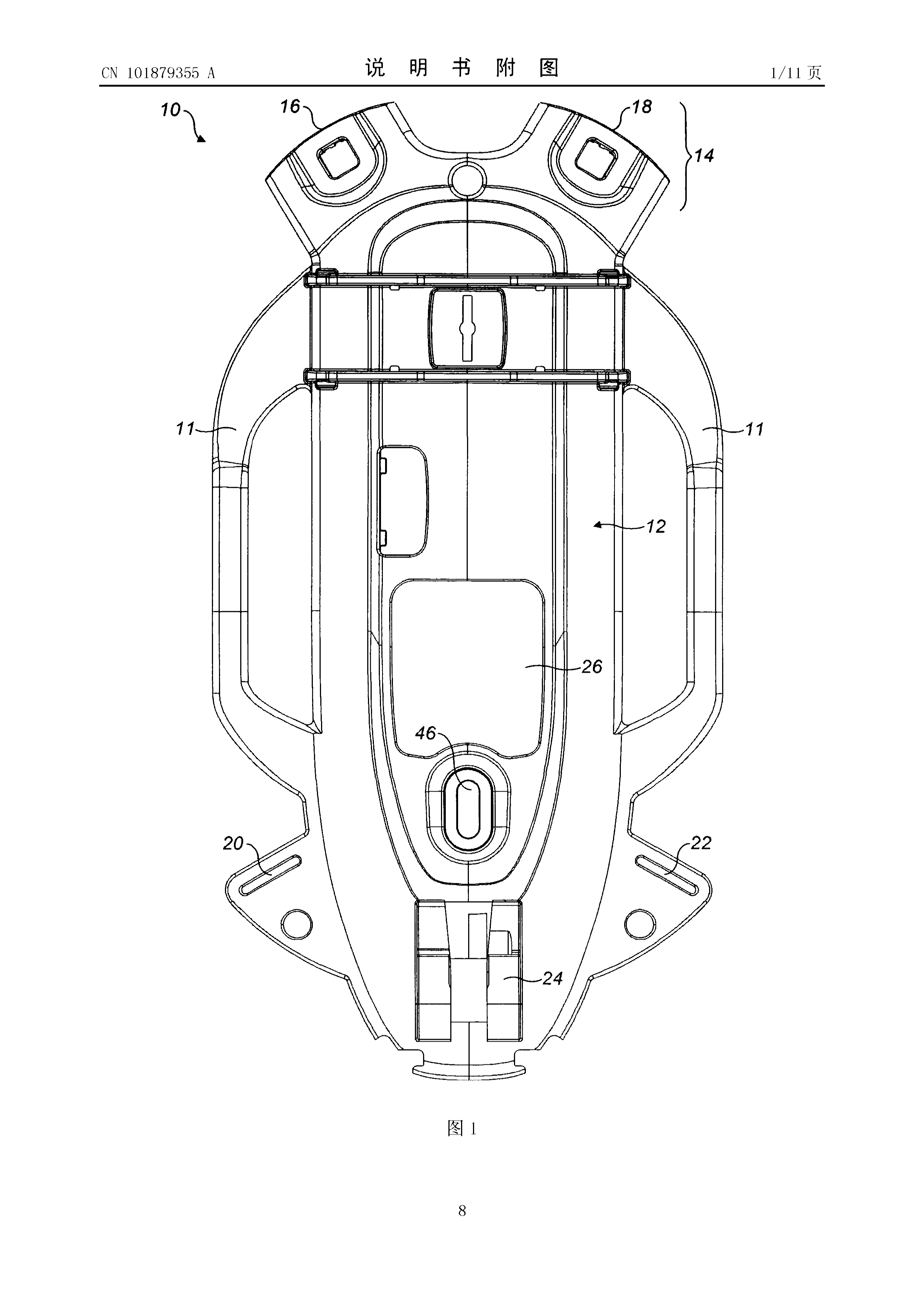
[0001] The present invention relates to a harness for a respirator, in particular a harness for a respirator with a structural support member including a guide groove for a flexible catheter.
Background technique
[0002] The equipment of a self-control breathing apparatus (SCBA) includes a structural support component in the form of a back plate (or back frame), a pair of shoulder straps and a waist belt. The back plate is provided with a valve and a fixing belt toward the lower end thereof. When in use, a gas cylinder that can inhale gas is connected to the valve and fixed to the back plate by a fixing strap. Many flexible tubes extend from the valve to the shoulder strap so that the respirator worn by the user can be easily connected to it.
[0003] It is known that in order to guide the flexible tube from the valve to the shoulder strap, a groove is provided on the back plate. The location of these slots usually determines on which shoulder strap the tube is located. However, regarding the positioning of these tubes, individual users or group users have different preferences.
[0004] For example, some fire brigades specify that all tubes must be worn on the left shoulder strap, while other fire brigades specify that all tubes must be worn on the right shoulder strap. In addition, individual users may prefer to have one tube on the left shoulder and the other on the right shoulder.
[0005] In order to take into account the preferences of individual users or group users, it is necessary to produce differently configured backplanes, which is very expensive, or the tube must follow a route other than the guide groove, which will cause the tube to become tangledofrisk (snagging risk)ο
[0006] Therefore, it is desirable to provide a universal backplane.
Summary of the invention
[0007] According to a first aspect of the present invention, there is provided a device for a respirator, including: a structural support member having a front surface for accommodating a gas cylinder and a back surface for facing the back of the wearer, and Left and right; left and right shoulder straps, which are arranged toward the left and right of the structural support member, respectively, each shoulder strap has a first end connected to the upper part of the structural support member and connected to the structural support member The second end of the lower part; a plurality of flexible conduits extending from the lower part of the structural support member along the structural support member, each flexible conduit reaching a position on the left shoulder strap or the right shoulder strap; and the left guide groove and the right guide Slots, which are longitudinally along the structural support member and extend along the left and right sides, respectively, for accommodating flexible conduits; wherein at least one of the guiding slots is arranged to accommodate at least two flexible conduits.
[0008] The left guide groove and the right guide groove may each be arranged to accommodate at least two flexible conduits. The harness may also include a cross channel that extends laterally through the structural support member from one side to the other for accommodating at least one flexible conduit. Preferably, the transverse guide groove extends through the upper part of the structural support member.
[0009] The guide groove may be located on the back of the structural support member.
[0010] In a preferred embodiment, before at least one of the flexible conduits extends along the structural support member in the guide groove, the at least one flexible conduit extends from the front face of the lower part of the structural support member and passes through The opening in the back panel reaches the back of the structural support member.
[0011] A fixing device may be provided for fixing the flexible catheter in the guide groove. The fixing device may include a clamping element arranged in the guide groove. Alternatively or additionally, the guide groove may be shaped to provide a fixing device.
[0012] In a preferred embodiment, the upper part of the structural support member includes a hub portion having a left shoulder strap connection portion and a right shoulder strap connection portion, and the first ends of the left shoulder strap and the right shoulder strap are respectively connected to the left shoulder strap connection portion and the right shoulder strap. The shoulder strap connecting portion, at least one of the shoulder strap connecting portions has first and second guide grooves, and the guide grooves are arranged to guide the flexible catheter to the position on the respective shoulder strap. The left shoulder strap connecting portion and the right shoulder strap connecting portion may each have first and second guide grooves.
[0013] The flexible conduit may be arranged to be held between the guide groove of the yoke and the shoulder strap.
[0014] The flexible conduit may include a high-pressure pipe and a medium-pressure pipe. The flexible conduit may include one or more cables.
[0015] According to another aspect of the present invention, there is provided a device for a respirator, including: a structural support member having a front surface for accommodating a gas cylinder and a back surface for facing the back of the wearer, and a left Side and right side; left shoulder strap and right shoulder strap, which are respectively arranged toward the left and right side of the structural support member, each shoulder strap has a first end connected to the upper part of the structural support member and a first end connected to the structural support member The second end of the lower part; a plurality of flexible conduits extending from the lower part of the structural support member along the structural support member, each flexible conduit reaching a position on the left shoulder strap or the right shoulder strap; the left guide groove and the right guide groove, It runs longitudinally along the structural support member, and extends along the left and right sides, respectively, for accommodating the flexible conduit; and a lateral guide groove that extends laterally through the structural support member from one side to the other The upper area of the guide groove is used to accommodate at least one flexible conduit; wherein, the transverse guide groove has a first end close to the upper end of the left guide groove, and a second end close to the upper end of the right guide groove. Preferably, at least one of the left guide groove and the right guide groove is arranged to accommodate at least two flexible conduits.
[0016] The present invention may include any combination of the features and/or limitations mentioned herein, unless the combination of these features is mutually exclusive.
Description of the drawings
[0017] The embodiments of the present invention will now be described with reference to the accompanying drawings by way of example only, in which:
[0018] FIG. 1 schematically shows a front view of a back plate of a respirator according to an embodiment of the present invention;
[0019] FIG. 2 schematically shows a rear view of the back plate of FIG. 1;
[0020] FIG. 3 schematically shows a front view of a harness for a respirator, the harness including the back plate of FIGS. 1 and 2;
[0021] FIG. 4 schematically shows a rear view of the harness of FIG. 3;
[0022] FIG. 5 schematically shows a rear view of the back plate, and the flexible conduit is located in the guide groove in the first configuration;
[0023] FIG. 6 schematically shows a rear view of the back plate, and the flexible conduit is located in the guide groove in a second configuration;
[0024] FIG. 7 schematically shows a rear view of the back plate, and the flexible conduit is located in the guide groove in a third configuration;
[0025] FIG. 8 schematically shows a front view of a harness for a respirator, the harness including the back plates of FIGS. 1 and 2 arranged in an alternative manner;
[0026] FIG. 9 schematically shows a rear view of the back plate, and the flexible conduit is located in the guide groove in the first configuration;
[0027] FIG. 10 schematically shows a rear view of the back plate with the flexible conduit in the guide groove in the second configuration; and
[0028] FIG. 11 schematically shows a rear view of the back plate, and the flexible conduit is located in the guide groove in a third configuration.
Detailed ways
[0029] FIG. 1 shows a structural support member 10 (hereinafter referred to as a back plate) of a harness for a respirator. The back plate 10 has a front surface 12 configured to have a gas cylinder for inhalable gas mounted thereon. The back plate has Noir 14, the Noir
14 is located in the upper area of the back plate 10. Noir 14 includes a left shoulder strap connecting portion 16 and a right shoulder strap connecting portion 18 to allow the upper ends of the left and right shoulder straps to be connected to the back plate 10. Toward the lower end of the back plate 10, a left shoulder strap connecting portion 20 and a right shoulder strap connecting portion are provided Part 22 to allow the lower ends of the left and right shoulder straps to be connected to the back plate 10.
[0030] The lower portion of the back plate 10 also includes a reduction valve installation portion 24 to allow the gas cylinder reduction valve to be installed on the back plate 10. An opening 26 is provided in the back plate, and the flexible conduit can pass through the opening 26 when in use. A first side handle and a second side handle, or legs 11 are provided so that the back panel 10 can be carried by the user.
[0031] FIG. 2 shows the back side 28 of the back plate 10. The back side 28 of the back plate 10 includes a left guide groove 30 and a right guide groove 32, which respectively extend longitudinally from the lower part to the upper part along the left and right sides of the back plate 10. A lateral guide groove 34 is also provided, which extends laterally through the back plate 10 from the left side to the right side. The left (or first) end of the transverse guide groove 34 is close to the upper end of the left guide groove 30, and the right (or second) end of the transverse guide groove 34 is close to the upper end of the right guide groove 32.
[0032] In this embodiment, each of the left guide groove 30 and the right guide groove 32 is arranged to accommodate two flexible conduits. In other embodiments, the left guide groove 30 and the right guide groove 32 may include a first left groove and a second left groove, and a first right groove and a second right groove. In order to improve flexibility, at least one of the left guide groove and the right guide groove is arranged to accommodate at least two flexible conduits.
[0033] The guide grooves 30, 32 are shaped with protrusions located inside and along their length, the protrusions being arranged to fix the flexible conduit in the groove. However, as it will be obvious to those skilled in the art, it is also possible to use other means for fixing the flexible catheter in the groove.
[0034] The left shoulder strap connecting portion 16 and the right shoulder strap connecting portion 18 of the yoke 14 are also close to the upper ends of the left guide groove 30 and the right guide groove 32, respectively. The left shoulder strap connecting portion 16 is provided with first and second guide grooves 36, 38, and the right shoulder strap connecting portion 18 is also provided with first and second guide grooves 40, 42.
[0035] A groove 44 is provided in the central portion of the back side 28 of the back plate 10. For example, the groove 44 is arranged to accommodate accessories of the respirator, such as a battery, a pressure sensor or a radio remote sensing device. The groove 44 separates the left guide groove 30 and the right guide groove 32.
[0036] A waist belt mounting portion 46 is also provided on the back side 28 of the back panel 10 so that the waist belt can be pivotally mounted to the back panel 10.
[0037] FIG. 3 shows a harness 100, which includes a back plate 10 as described above. The left shoulder belt 110 and the right shoulder belt 120 are connected to the shoulder belt fixing portions 16, 18, 20, 22, and the waist belt 130 is connected to the waist belt mounting portion 46. The gas cylinder reduction valve 140 is connected to the lower part of the back plate 10 by using the reduction valve installation part 24. In this embodiment, two flexible conduits 150, 152 extend from the reduction valve 140 to a position on the left shoulder strap 110. The flexible pipe includes a high-pressure pipe 150 and a medium-pressure pipe 152. When in use, a gas cylinder (not shown) that can breathe gas is installed on the front surface 12 of the back plate 10, and is connected to the reduction valve 140 at the first end, and fixed with a cylinder fixing strap (not shown) at the second end To the back panel 10. The breathable gas is delivered through the high pressure tube 150 to the pressure gauge 160 and through the medium pressure tube 152 to the connector 162, which can be connected to a breathing mask (not shown). As shown in FIG. 3, the flexible conduits 150, 152 pass through the front surface 12 of the backplane 10, pass through the opening 26 to reach the back surface 28 of the backplane 10.
[0038] Referring now to FIG. 4, the high-pressure pipe 150 and the intermediate-pressure pipe 152 are located in the left guide groove 30 in the back side 28 of the back plate 10. In the left guide groove 30, the high-pressure pipe 150 and the intermediate-pressure pipe 152 extend longitudinally upward along the left side of the back plate 10. As shown in FIG. 5, the high-pressure pipe 150 leaves the left guide groove 30 and enters the first guide groove 36 of the left shoulder strap connecting portion 16, and the medium pressure pipe 152 leaves the left guide groove 30 and enters the second guide groove of the left shoulder strap connecting portion 16.groove38. The tubes 150, 152 are fixed in the first and second guide grooves 36.38 by the shoulder strap 110. Then as shown in Figure 3, the tubes 150, 152 extend along the shoulder strap 110 and pass through the flap
(flap) 112 remains in place.
[0039] As shown in FIG. 6, the high-pressure tube 150 and the medium-pressure tube 152 can be taken out of the left guide groove 30 and placed in the right guide groove 32 if the wearer desires. Then, the tubes 150, 152 are located in the first and second guide grooves 40, 42 of the right shoulder strap connection portion 18. This allows the high pressure tube 150 and the intermediate pressure tube 152 to be located on the right shoulder strap 120.
[0040] In another configuration, and as shown in FIG. 7, the high-pressure pipe 150 and the intermediate-pressure pipe 152 are located in the right guide groove 32. Then the high-pressure pipe 150 is located in the transverse guide groove 34 to take it from the right side of the back plate 10 to the left side of the back plate 10. Thus, the high-pressure tube 150 is located in the second guide groove 28 of the left shoulder strap connecting portion 16. The intermediate pressure tube is located in the first guide groove 40 of the right shoulder strap connecting portion 18. This allows the high pressure tube 150 to be located on the left shoulder belt 110 and the medium pressure tube 152 to be located on the right shoulder belt 120.
[0041] As it will be obvious to those skilled in the art, other configurations of the arrangement of guide grooves in the backplane are possible.
[0042] As shown in FIG. 8, in the second configuration, three flexible conduits 150, 152, 154 extend from the speed reducer 140 mounted on the back plate 10. A second medium pressure tube 154 is provided to allow connection of the breathing mask of the second user in an emergency. The three tubes 150, 152, 154 pass through the opening 26 in the back plate 10 to the back side 28 of the back plate. The high pressure tube 150 extends to a position on the right shoulder belt 120, the first intermediate pressure tube 152 extends to a position on the right shoulder belt 120, and the second intermediate pressure tube 154 extends to a position on the left shoulder belt 110. The tubes 150, 152, 154 are held in place by the flaps 112, 122.
9, the high-pressure pipe 150 and the second intermediate-pressure pipe 154 are located in the left guide groove 30 in the back side 28 of the back plate 10. The first intermediate pressure tube 152 is located in the right guide groove 32. The high-pressure pipe 150 is then located in the lateral guide groove 34, which takes it from the left side of the back plate 10 to the right side of the back plate 10. Then the high-pressure tube 150 is located in the second guide groove 42 of the right shoulder strap connecting portion 18. The first and second intermediate pressure tubes 152 and 154 are respectively located in the first guide grooves 40 and 36 of the right shoulder strap connecting portion 18 and the left shoulder strap connecting portion 16.
[0044] In another configuration shown in FIG. 10, the high pressure pipe 150 and the first intermediate pressure pipe 152 are located in the right guide groove 32, and the first intermediate pressure pipe 154 is located in the left guide groove 30. Then the first intermediate pressure tube 152 extends from the right side of the back plate 10 to the left side of the back plate 10 in the lateral guide groove 34. The high-pressure pipe 150 is located in the first guide groove 40 of the right shoulder strap connection part 18, and the first and second intermediate pressure pipes 152, 154 are located in the guide grooves 16, 18 of the left shoulder belt connection part 16. This allows the high pressure tube 150 to be located on the right shoulder belt 120, and the first and second intermediate pressure tubes 152>154 to be located on the left shoulder belt 110.
[0045] As will be apparent to those skilled in the art, other configurations of pipes in the guide groove are possible.
[0046] As shown in FIG. 11, in an alternative arrangement, the high-pressure pipe 150 extends from the reducer 140 and is connected to a pressure sensor (not shown) to transform the pressure delivered through the pipe 150 into electric signal. The electrical signal is output through the cable 156 located in the left guide slot 30. The cable 156 is located on the left shoulder strap 110 and is connected to the electronic display device 162.
[0047] The arrangement of the guide grooves allows the user to configure his respirator to suit his specific needs or preferences. Different users like different arrangements, and different respirators have different numbers of tubes. The back plate 10 according to the present invention allows a wide variety of tube configurations.
11 sheets
Sheet 1 Sheet 2 Sheet 3 Sheet 4 Sheet 5 Sheet 6 Sheet 7 Sheet 8 Sheet 9 Sheet 10 Sheet 11
Every citation, both ways
| Document | Relation | Office | Cited during |
|---|---|---|---|
| CN103458972A | Cited by | China | Search report |
| CN108883318A | Cited by | China | Search report |
| US10850138B2 | Cited by | United States of America | Applicant |
| EP1952718A1 | Cites | European Patent Office (EPO) | Search report |
| EP1952719A1 | Cites | European Patent Office (EPO) | Search report |
11 members in 4 offices
Priority claims5
| Document | Office | Kind | Date |
|---|---|---|---|
| 0907754 | United Kingdom | A | |
| 0907754 | United Kingdom | A | |
| 09077546 | United Kingdom | – | |
| 09077546 | – | – | – |
| GB20090007754 | – | – | – |
Members11
| Document | Office | Kind | |
|---|---|---|---|
| GB0907754D0 | United Kingdom | D0 | |
| CN101879355AThis record | China | A | |
| EP2248557A1 | European Patent Office (EPO) | A1 | |
| GB2470032A | United Kingdom | A | |
| US2010282252A1 | United States of America | A1 | |
| US8608040B2 | United States of America | B2 | |
| GB2470032B | United Kingdom | B | |
| CN101879355B | China | B | |
| EP2248557B1 | European Patent Office (EPO) | B1 | |
| EP3097953A1 | European Patent Office (EPO) | A1 | |
| EP3097953B1 | European Patent Office (EPO) | B1 |
3 legal events, as the office reported them to INPADOC
Over the term
Point at a mark for the eventEvents
| Event | Code | |
|---|---|---|
| Patent grantGrantedGR01 | GR01 | |
| Entry into substantive examinationC10 | C10 | |
| PublicationC06 | C06 |
Numbers
- Publication
- 101879355
- Publication, DOCDB
- 101879355
- Publication, EPODOC
- CN101879355
- Application
- 101657385
- Application, DOCDB
- 201010165738
- Application, EPODOC
- CN20101165738
Titles2
- Chinese
- 改进的用于呼吸器的装具
- English
- Improved equipment for breathing apparatus
Classification
- CPC, 5
- A62B25/00
- A62B9/04
- A45F3/04
- A45F3/10
- A45F3/14
- IPC, 2
- A62B9 00
- A62B9 04