System, method and apparatus for secure transmission of confidential information
Summary by NHIP
Infrared-to-Radio Secure Link
The system establishes secure wireless radio links by first exchanging encryption data via infrared signals. Mobile stations transmit security requests in infrared mode before switching to radiofrequency mode for encrypted message transceiving.
Claim Score by NHIP
Abstract
A system, method and apparatus for establishing a secure wireless radio communications link between two devices that minimizes the exposure of sensitive information to third party interception is disclosed. The secure link is established by first establishing an infrared link between the two devices for the exchange of sensitive information, such as encryption information. Subsequent communications would then have the benefit of encryption protection, establishing the secure wireless radio communications link.
Term
Term ended
Expired 11 February 2018, 8.6 years ago.
- Priority and filed
- Granted
- Expired
- Today
38 claims: 5 independent, 33 dependent
- 1A private telecommunications system for secure wireless communications, said private telecommunications system comprising:a private base station having transceiving means therein for communicating in a first and a second communication mode;at least one mobile station, in wireless communication with said private base station, said at least one mobile station wirelessly communicating with said private base station in said first communication mode using an infrared signal and in said second communication mode using a radiofrequency signal;and wherein, prior to communicating in said second communication mode, said at least one mobile station transmits a request message in said first communication mode to said base station to request security-related data for use in conducting said communications in said second communication mode between said at least one mobile station and said base station.
- 13A method for establishing a secure communication link between a dual-mode mobile station and a dual-mode private base station of a private telecommunication system, a first mode of said dual-mode being an infrared mode and a second mode of said dual-mode being a radiofrequency mode, said method comprising the steps of:forwarding an infrared request message from said mobile station to said base station to establish a secure communication link in said infrared mode to request security-related data for use in conducting said second communication mode between said at least one mobile station and said base station;establishing said secure communication link between said mobile station and said private base station, said secure communication link operating in said infrared mode;and transferring, during said secure communication link, a security message between said mobile station and said private base station in said infrared mode.
- 21Broadest claimClaim Score 66, broad(NHIP)A mobile station for secure wireless communications in a private telecommunications system, said mobile station comprising:radiofrequency transceiving means for transceiving a plurality of radiofrequency transmissions within said private telecommunications system;infrared transceiving means for transceiving a plurality of infrared transmissions within said private telecommunications system;and wherein, prior to transceiving said plurality of radiofrequency transmissions, transceiving an infrared request signal between said mobile station and a base station to request security-related data for use in encrypting said plurality of radiofrequency transmissions.
- 27A private base station for secure wireless communications in a private telecommunications system, said private base station comprising:radiofrequency transceiving means for transceiving a plurality of radiofrequency transmissions within said private telecommunications system;infrared transceiving means for transceiving a plurality of infrared transmissions within said private telecommunications system;and wherein prior to transceiving said plurality of radiofrequency transmissions, transceiving an infrared request signal between said base station and a mobile station to request security-related data for use in encrypting said plurality of radiofrequency transmissions.
- 33A method for providing secure communications between a mobile station and a base station in a private telecommunications system, comprising the steps of:transmitting an infrared request message between said mobile station and said base station, said infrared request message transmitted in an infrared mode;transmitting an infrared response message in said infrared mode between said mobile station and said base station in response to the infrared request message, said infrared response message including security-related data for use in connection with communications between the mobile station and the base station;and establishing a secure communication link using the security-related data for use in communicating between the mobile station and the base station in a radiofrequency mode.
Independent claims5
33 paragraphs in 5 sections, as filed
BACKGROUND OF THE PRESENT INVENTION
Field of the invention
The present invention relates generally to a system, method and apparatus for establishing a secure wireless communications link between two devices that minimizes the risk of third party interception of sensitive information, such as may be exchanged during communication initialization.
BACKGROUND AND OBJECTS OF THE PRESENT INVENTION
The evolution of wireless communication over the past century, since Guglielmo Marconi's 1897 demonstration of radio's ability to provide continuous contact with ships sailing the English Channel, has been remarkable. Since Marconi's discovery, new wireline and wireless communication methods, services and standards have been adopted by people throughout the world. This evolution has been accelerating, particularly over the least ten years, during which the mobile radio communications industry has grown by orders of magnitude, fueled by numerous technological advances that have made portable radio equipment smaller, cheaper and more reliable. The exponential growth of mobile telephony will continue to rise in the coming decades as well, as this wireless network interacts with and eventually overtakes the existing wireline networks.
Cordless telephony has also been a part of the exponential rise in wireless telephony. Cordless telephones were originally aimed at providing economical, tetherless voice communications inside residences, i.e., using a short wireless link to replace the cord between a telephone base unit and its handset. Although early cordless phones were of marginal quality, with the introduction of improved cordless phones in the 1980s sales dramatically increased. More recent advances, particularly in Europe, have extended the use domain of cordless phones outside of residences.
Another European revolution of cordless telephones is the digital enhanced cordless communications (DECT) standard, which was optimized for use inside buildings. DECT controllers may hand off active calls from one base unit to another as the users move, and can page or ring handsets as a user walks through areas covered by different base units. As is understood in the art, however, the range of cordless telephones is greatly limited compared to the more versatile cellular telephones, i. e., 0.3-30 or more kilometer range for cellular and less than 100 meters in cordless systems, and usually only up to tens of meters.
More recently, the worlds of cellular and cordless telephony have begun to converge with the introduction of cordless standards compatible with that of its cellular cousin. Accordingly, a mobile cellular user may utilize their cellular telephones within a cordless telephony system, thereby avoiding the need to purchase proprietary and typically non-compatible cordless telephones. Shown in FIG. 1 is a private telephone system, generally referred to by the numeral <b>10</b>, having at least one private base station <b>12</b> and a multiplicity of cellular phones <b>14</b> in communication therewith. When in a cordless mode a cellular user, e.g., at phone <b>14</b>A, may communicate with another user within the private telephone system <b>10</b>, e.g., another cordless-mode cellular phone <b>14</b>B or a cordless phone <b>16</b>, via the private base station <b>12</b> which serves as a relay.
One problem with the use of the cellular phones <b>14</b> within the private telephone system <b>10</b> is security. As discussed, original cordless telephones, e.g., phones <b>16</b> in FIG. 1 were stand-alone consumer products that did not require any interoperability specifications. In other words, each cordless phone came with its own base station and needed to be compatible only with that base station. Billing, security and privacy concerns within such systems were addressed by both preventing that cordless phone from operating with any other base station and limiting the transmission range of the cordless phones. With the convergence of cordless and cellular technologies and the use of interoperability specifications, however, the inherent physical limitations of the cordless systems no longer serve a security function. With cellular phones <b>14</b> being capable of transmitting their signals over many kilometers, the use of such phones within private telephone systems <b>10</b> raise genuine security considerations.
As is understood in the art, cellular phone <b>14</b>A may communicate through the private base station <b>12</b> by use of encryption keys or other such security protocol, whereby the messages are encrypted and more difficult to decipher. Accordingly, even though the communications from a cellular user communicating within the private telephone system <b>10</b> may extend well outside the outer reaches of the system <b>10</b>, the conversation or data exchanged is kept relatively confidential. Another problem, however, arises during communication initialization over the radio interface which must occur without encryption since no encryption keys have been exchanged between the cellular user, e.g., of cellular terminal <b>14</b>A. The information is therefore being broadcast across a wide range, including the keys, until encryption protocols are established. Accordingly, third parties may listen in on such pre-encryption transmissions and acquire sensitive information.
Various techniques may be employed to thwart such eavesdropping. A first approach is to use a wireline connection for the initial information exchange, whereby the cellular phone <b>14</b>A must be electrically connected to the private base station to start the private communication. This approach would, accordingly, require the definition of an electrical interface between the two components and limit the manufacturer's freedom to design attractive terminals since a standardized connector may increase the size and weight of the terminal. Further, such a definition may also restrict further improvements of such phones <b>14</b>, e.g., moving to lower voltage technologies for energy conservation and size deduction.
An alternative approach would be using Subscriber Identity Modules (SIMs) in both the private base station <b>10</b> and the respective cellular terminal <b>14</b>, whereby the requisite identification information is readily established and the proper keys applied without transmitting them. In addition to the added component costs, the use of two SIMs in this manner also adds to the administrative costs of mobile network operators who must allocate unique SIM pairings between the private base stations <b>20</b> and respective cellular terminals <b>14</b>. Furthermore, there is a risk that a SIM meant for the cellular terminal <b>14</b> may instead be inserted into the private base station <b>12</b>, further complicating this approach.
A third approach is to utilize the advantages of the radio interface, e.g., standardization. As discussed, however, because radio waves propagate through walls and over large distances, this also poses a security risk which must be overcome.
In view of the disadvantages of each of the aforementioned approaches, it is clear that there is a need for a simple and secure system and method for establishing a communications link between a first device, such as a cellular phone, and another device, such as a private base station.
It is, accordingly, an object of the present invention to provide a system, method and apparatus for establishing such a simple and secure communications link, whereby at least a portion of a transmission, particularly one containing sensitive information, may be transmitted clearly for proper reception while simultaneously minimizing the risk of interception.
SUMMARY OF THE INVENTION
The present invention is directed to a system, method and apparatus for establishing a secure wireless radio communications link between two devices that minimizes the exposure of sensitive information to third party interception. The secure link is established by establishing an infrared link between the two devices for the exchange of sensitive information, such as encryption information. Subsequent communications would then have the benefit of encryption protection, establishing the secure wireless radio communications link.
A more complete appreciation of the present invention and the scope thereof can be obtained from the accompanying drawings which are briefly summarized below, the following detailed description of the presently-preferred embodiments of the invention, and the appended claims.
BRIEF DESCRIPTION OF THE DRAWINGS
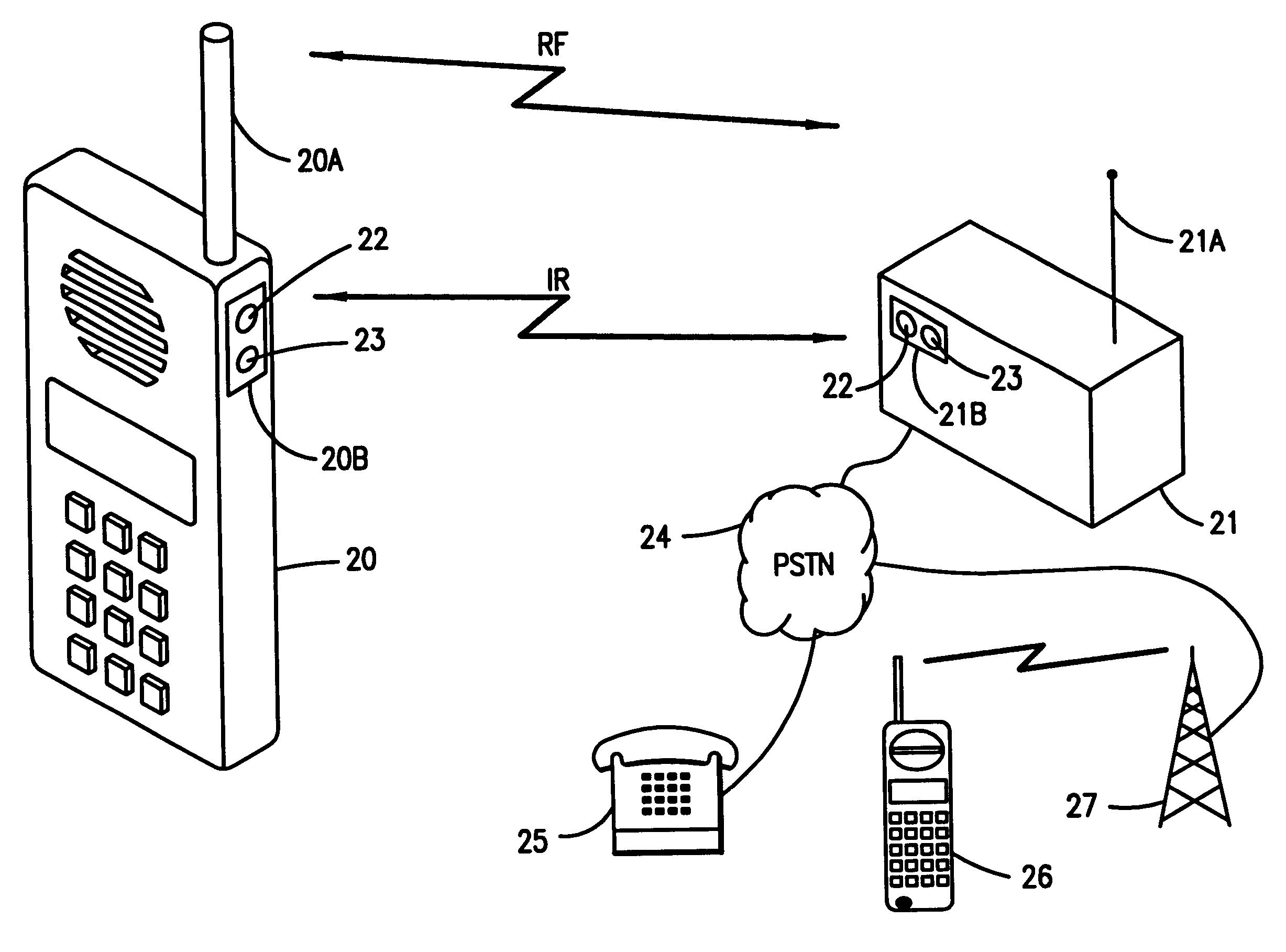
FIG. 1 is a schematic illustration of a private telephone system, including a private base station with cellular and cordless phones in communication therewith;
FIG. 2 illustrates a dual-mode radiofrequency and infrared mobile station and private base station in accordance with the present invention; and
FIG. 3 illustrates various circuitry employed in the dual-mode devices shown in FIG. <b>2</b>.
DETAILED DESCRIPTION OF THE PRESENTLY PREFERRED EXEMPLARY EMBODIMENTS
The present invention will now be described more fully hereinafter with reference to the accompanying drawings, in which preferred embodiments of the invention are shown. This invention may, however, be embodied in many different forms and should not be construed as limited to the embodiments set forth herein; rather, these embodiments are provided so that this disclosure will be thorough and complete, and will fully convey the scope of the invention to those skilled in the art.
The use of infrared (IR) transmissions between diverse electronic devices, e.g., between a television and a remote controller, are known, e.g., U.S. Pat. Nos. 5,508,836, 5,588,009, 5,564,020, 5,617,236 and 5,446,783 each describe various IR-electronic interconnections. U.S. Pat. No. 5,636,264 similarly describes an IR interface between a phone handset and a computer. Although generally describing the usage of IR in these contexts, the references fail to discuss the aforementioned security problems inherent in wireless communications nor the proposed solution set forth in the present invention, described in more detail hereinafter.
Shown in FIG. 2 is a dual mode mobile station <b>20</b> in communication with a dual mode private base station <b>21</b>. As discussed, mobile station <b>20</b> communicates with the private base station <b>21</b> via an RF transmission, which has an effective range of hundreds of meters, and via a more limited, “cordless” communications mode having a much shorter, contained range. As is understood in the art, the RF transmission mode is via the respective antennae <b>20</b>A and <b>21</b>A of the mobile station <b>20</b> and private base station <b>21</b>, respectively, the signals being transceived in a conventional manner.
Also shown in FIG. 2 are IR transceiver interfaces <b>20</b>B and <b>21</b>B on the mobile station <b>20</b> and private base station <b>21</b>, respectively. Each interface preferably includes a photodetector <b>22</b> for receiving IR signals and an IR signal emitter <b>23</b> for transmitting such IR signals. It should be understood that the position of the interfaces <b>20</b>B and <b>21</b>B on the respective bodies of the mobile station <b>20</b> and the private base station <b>21</b> are arbitrary, provided the respective IR signals to and from the interfaces <b>20</b>B and <b>21</b>B are not blocked, e.g., by the palm or fingers of the phone user. In other words, ergonomic considerations may dictate particular placements for the interfaces, as is understood in the art.
With further reference to FIG. 2, one of the practical utilizations of the dual-mode mobile station <b>20</b> is now illustrated. In particular, when the dual-mode mobile station <b>20</b> comes within the more limited range of the private base station <b>21</b>, e.g., in the same or an adjacent room, the subscriber may wish to transfer control from the cellular provider to the private system, e.g., to save money on the cheaper wireline phone rates through the private system to the Public Switched Telephone Network (PSTN). For example, through the PSTN <b>24</b>, the mobile station <b>20</b> can communicate with remote wireline phones <b>25</b> and remote cellular phones <b>26</b> via a base transceiver system <b>27</b>(shown for simplicity as a base transceiver station tower).
With reference now to FIG. 3 of the drawings, there is illustrated a portion of the mobile station <b>20</b> (in FIG. <b>2</b>), particularly, the IR transceiver interface <b>20</b>B and various circuitry within the mobile station <b>20</b> for handling the IR signals. An IR receiver or photodetector <b>30</b> receives the IR signals, such as from the private base station <b>21</b>, and passes the signals to a decoder <b>31</b>, which converts the infrared information within the IR signal to electrical information, e.g, digital pulses. The converted information is then forwarded to a controller <b>32</b>, which controls the flow of the electrical information (pulses). A signal conversion device <b>33</b> receives the aforesaid electrical information flow and groups the incoming pulses into a unit size (frame) pursuant to a known signal format. The controller <b>32</b> may be a UART or other like controller, as is understood in the art.
The incoming signal, now translated, is sent to a processor <b>34</b>, which implements the command(s) set forth in the signal, e.g., forward the incoming signal to another phone such as mobile station <b>14</b>B (in FIG. 1) across the RF communications link. Similarly, the processor <b>34</b>, in response to one or more commands, may send a message across the IR communications link by first forwarding the message to the signal conversion device <b>33</b>, which converts the structured message into the aforesaid electrical information or pulses, which the controller <b>32</b> sends to an encoder <b>35</b>. The electrical pulses are there converted to IR radiation signals which are then transmitted by an IR transmitter <b>36</b>, e.g., light emitting diodes, releasing the IR signal. It should, of course, be understood that the circuitry shown in FIG. 3 is preferably also incorporated within the private base station <b>21</b> so that a wireless IR dialogue may be established with the mobile station <b>20</b>.
As discussed, the effective range of the IR signal so emitted is limited, e.g., on the order of several dozens of meters. With obstacles like walls, floors and ceilings, the effective range is even further reduced, as is encountered by consumers with products such as television remotes. Accordingly, IR signals provide an excellent way to exchange confidential information wirelessly, effectively limiting communications to a point-to-point conversation, albeit preferably temporarily until the security protocols are safely established. Eavesdropping, although still possible, is thwarted by such range restrictions since other security measures, e.g., building control, may be employed in conjunction to provide almost any level of interception prevention.
Since various encryption methods are available to make a wireless conversation almost impervious to code-breakers, wireless communications between a user of the dual-mode phone <b>20</b> (in FIGS. 2 and 3) preferably switches to the RF communications mode to utilize the enhanced security advantages of encryption to prevent deciphering. Wireless RF communications, however, even with encryption, are easily intercepted by a distant eavesdropper. Although encryption data may thwart the eavesdropper's deciphering the intercepted coded message, the caller and recipient must first establish the secure transmission through the exchange of encryption keys over a non-encrypted wireless communication, which the eavesdropper can monitor, easily decipher the pertinent keys and then decipher the supposedly secure encrypted transmissions.
The system, method and apparatus of the present invention provide an improved, more secure way to preserve the confidentiality of wirelessly transmitted information by restricting exposure of the encryption keys and any other confidential information through use of the aforementioned IR transmissions.
In one embodiment of the present invention the subscriber of mobile station <b>20</b> when sufficiently close to the private telephone system, e.g., near the private base station <b>21</b>, activates the mobile station <b>20</b> to emit an IR signal, e.g., via IR transmitter <b>36</b>. Alternatively, the mobile station <b>20</b> may activate IR signaling capability automatically in advance of transceiving any security-related data. In a preferred embodiment of the present invention, the mobile station utilizes conventional radiofrequencies for all non-security-related transmissions, e.g., when initiating communications with the private base station <b>21</b> such as a cordless telephone base station and after the exchange of encryption or other such security data. Upon reaching the aforementioned security data or protocols in the transmission, the mobile station <b>20</b> then switches over to the aforementioned IR signaling using the IR transmitter <b>36</b>. It should be understood, that the RF-to-IR switchover may occur early in the transmission, e.g., in the initial communications attempts, or later during the transmission, so long as any secured portions of the signal are transmitted via IR transmissions.
In either event, the private base station <b>21</b> detects the IR signal transmission from the mobile station <b>20</b>, via the aforementioned photodetector <b>30</b> in the station <b>21</b>, processes the incoming IR signal, and responds with an IR response signal, which preferably includes an encryption key. It should be understood that one or more encryption keys may be inserted into the response signal by an encryption device <b>37</b> in communication with the processor <b>34</b>. Upon the secure receipt of the encryption key(s) from the private base station <b>21</b> via IR transmission, the mobile station <b>20</b> may then safely begin/resume wireless RF communications, which are now encrypted pursuant to the embedded encryption key(s). The subscriber is then able to move more freely throughout the building, all the while taking advantage of the inexpensive wireline communications link through the PSTN <b>24</b>, as discussed hereinbefore.
In another embodiment of the present invention, the private base station <b>21</b> may periodically emit an IR signal, which the mobile station <b>20</b> may intercept, if close enough. In effect, the private base station may perform an IR poll to establish the preliminary IR linkage to exchange security information, such as the aforedescribed encryption keys. For example, upon detection (in photodetector <b>30</b>), the mobile station <b>20</b> may (like the private base station <b>21</b> in the previous embodiment) also respond with an IR response signal, which may include encryption key(s) for governing the subsequent RF transmissions with the private base station <b>21</b>, thereby providing a procedure for periodic or random security measures.
In still another embodiment of the present invention, the more secure IR communications link may be employed by the subscriber of the mobile station <b>20</b> or an administrator of the private telephone system to transfer other, noninitialization-related information. For example, if particularly sensitive information needs to be transmitted during an RF communication, the mobile station <b>20</b> and private base station <b>21</b> may switch to the more private IR communications mode and resume the RF mode transmissions after the sensitive information has been transferred. It should also be understood that the mobile station <b>20</b> and private base station <b>21</b> may automatically revert to the IR communication mode while in range of each other and only switch over when the IR transmissions begin to deteriorate.
The previous description is of preferred embodiments for implementing the invention, and the scope of the invention should not necessarily be limited by this description. The scope of the present invention is instead defined by the following claims.
Contents5
3 sheets
Sheet 1 Sheet 2 Sheet 3
Every citation, both ways
| Document | Relation | Office | Cited during |
|---|---|---|---|
| US7869824B2 | Cited by | United States of America | Search report |
| US7328045B2 | Cited by | United States of America | Search report |
| US7423982B2 | Cited by | United States of America | Search report |
| US6763195B1 | Cited by | United States of America | Search report |
| US2004264701A1 | Cited by | United States of America | Pre-grant |
| US7567828B1 | Cited by | United States of America | Search report |
| US7110678B2 | Cited by | United States of America | Applicant |
| US2008057929A1 | Cited by | United States of America | Pre-grant |
| US6747566B2 | Cited by | United States of America | Search report |
| US2009060515A1 | Cited by | United States of America | Pre-grant |
| US8005364B2 | Cited by | United States of America | Applicant |
| US2009187982A1 | Cited by | United States of America | Pre-grant |
| US2002065099A1 | Cited by | United States of America | Pre-grant |
| US2003112978A1 | Cited by | United States of America | Pre-grant |
| US7549047B2 | Cited by | United States of America | Search report |
| US7505768B2 | Cited by | United States of America | Search report |
| US8566592B2 | Cited by | United States of America | Applicant |
| US6865401B2 | Cited by | United States of America | Search report |
| US2010227556A1 | Cited by | United States of America | Pre-grant |
| US2002171896A1 | Cited by | United States of America | Pre-grant |
| US6889009B2 | Cited by | United States of America | Search report |
| US2011134847A1 | Cited by | United States of America | Pre-grant |
| US6750780B1 | Cited by | United States of America | Search report |
| US2008155261A1 | Cited by | United States of America | Pre-grant |
| US2008123843A1 | Cited by | United States of America | Pre-grant |
| US7739503B2 | Cited by | United States of America | Search report |
| US2003149874A1 | Cited by | United States of America | Pre-grant |
| US8051297B2 | Cited by | United States of America | Search report |
| US8515389B2 | Cited by | United States of America | Search report |
| US8285326B2 | Cited by | United States of America | Search report |
| US2005143129A1 | Cited by | United States of America | Pre-grant |
| US2015046335A1 | Cited by | United States of America | Search report |
| US2005008371A1 | Cited by | United States of America | Pre-grant |
| US2002142769A1 | Cited by | United States of America | Pre-grant |
| EP2400717A3 | Cited by | European Patent Office (EPO) | Search report |
| US6782208B1 | Cited by | United States of America | Search report |
| EP1740003A4 | Cited by | European Patent Office (EPO) | Search report |
| US8126030B2 | Cited by | United States of America | Applicant |
| WO2004025901A2 | Cited by | World Intellectual Property Organization (WIPO) | International search |
| US2004208591A1 | Cited by | United States of America | Pre-grant |
| US8139942B2 | Cited by | United States of America | Search report |
| US7937752B2 | Cited by | United States of America | Applicant |
| EP2400717A2 | Cited by | European Patent Office (EPO) | Search report |
| US2004204028A1 | Cited by | United States of America | Pre-grant |
| US2006109824A1 | Cited by | United States of America | Pre-grant |
| US8156337B2 | Cited by | United States of America | Applicant |
| US2002149796A1 | Cited by | United States of America | Pre-grant |
| US7263361B2 | Cited by | United States of America | Search report |
| US2004103280A1 | Cited by | United States of America | Pre-grant |
| US2002149811A1 | Cited by | United States of America | Pre-grant |
| US10332081B2 | Cited by | United States of America | Search report |
| US7573845B2 | Cited by | United States of America | Search report |
| WO2004025901A3 | Cited by | World Intellectual Property Organization (WIPO) | International search |
| US6901241B2 | Cited by | United States of America | Search report |
| US2004259539A1 | Cited by | United States of America | Pre-grant |
| US2004047364A1 | Cited by | United States of America | Pre-grant |
| US2003090765A1 | Cited by | United States of America | Pre-grant |
| US2007155423A1 | Cited by | United States of America | Pre-grant |
| US2007025554A1 | Cited by | United States of America | Pre-grant |
| US2007047625A1 | Cited by | United States of America | Pre-grant |
| US2002123325A1 | Cited by | United States of America | Pre-grant |
| US2002126035A1 | Cited by | United States of America | Pre-grant |
| EP0756397A2 | Cites | European Patent Office (EPO) | Applicant |
| EP0806878A2 | Cites | European Patent Office (EPO) | Applicant |
| DE19629408A1 | Cites | Germany | Applicant |
| US4856046A | Cites | United States of America | Applicant |
| US4904993A | Cites | United States of America | Search report |
| US5034997A | Cites | United States of America | Search report |
| US5301353A | Cites | United States of America | Search report |
| US5404572A | Cites | United States of America | Search report |
| US5446783A | Cites | United States of America | Applicant |
| US5479595A | Cites | United States of America | Search report |
| US5508836A | Cites | United States of America | Applicant |
| US5564020A | Cites | United States of America | Applicant |
| US5585953A | Cites | United States of America | Search report |
| US5588009A | Cites | United States of America | Applicant |
| US5608723A | Cites | United States of America | Search report |
| US5617236A | Cites | United States of America | Applicant |
| US5617449A | Cites | United States of America | Applicant |
| US5636265A | Cites | United States of America | Applicant |
| US5659883A | Cites | United States of America | Search report |
| US5812293A | Cites | United States of America | Search report |
| US5819184A | Cites | United States of America | Applicant |
| US5835862A | Cites | United States of America | Applicant |
| US5844939A | Cites | United States of America | Applicant |
| US5850444A | Cites | United States of America | Search report |
| US5915021A | Cites | United States of America | Search report |
| US5917425A | Cites | United States of America | Search report |
| US5946120A | Cites | United States of America | Search report |
| US5953323A | Cites | United States of America | Search report |
13 members in 10 offices
Priority claims2
| Document | Office | Kind | Date |
|---|---|---|---|
| 2228998 | United States of America | A | |
| US19980022289 | – | – | – |
Members13
| Document | Office | Kind | |
|---|---|---|---|
| WO9941876A1 | World Intellectual Property Organization (WIPO) | A1 | |
| AU2650199A | Australia | A | |
| BR9907826A | Brazil | A | |
| EP1055307A1 | European Patent Office (EPO) | A1 | |
| CN1290438A | China | A | |
| KR20010034332A | Republic of Korea | A | |
| JP2002503920A | Japan | A | |
| EE200000467A | Estonia | A | |
| US6396612B1This record | United States of America | B1 | |
| US2002065099A1 | United States of America | A1 | |
| AU748426B2 | Australia | B2 | |
| US6901241B2 | United States of America | B2 | |
| MY119743A | Malaysia | A |
6 legal events, as the office reported them to INPADOC
Over the term
Point at a mark for the eventEvents
| Event | Code | |
|---|---|---|
| Lapsed due to failure to pay maintenance feeLapsedFP | FP | |
| Information on status: patent discontinuationPATENT EXPIRED DUE TO NONPAYMENT OF MAINTENANCE FEES UNDER 37 CFR 1.362STCH | STCH | |
| Lapse for failure to pay maintenance feesLapsedLAPS | LAPS | |
| Maintenance fee reminder mailedREMI | REMI | |
| Fee paymentFPAY | FPAY | |
| AssignmentAS | AS |
Numbers
- Publication, DOCDB
- 6396612
- Publication, EPODOC
- US6396612
- Application
- 9022289
- Application, DOCDB
- 2228998
- Application, EPODOC
- US19980022289
Titles
- English
- System, method and apparatus for secure transmission of confidential information
Classification
- CPC, 10
- H04L63/18
- H04L63/0492
- H04M1/725
- H04M2250/02
- H04L9/0838
- H04L9/0891
- H04L9/14
- H04L2209/80
- H04M1/72415
- H04M1/72412
- IPC, 5
- H04L9 08
- H04L29 06
- H04M1 72412
- H04M1 72415
- H04M1 725
- USPC, 5
- 398121000
- 340003430
- 340005200
- 398115000
- 398135000