Content provisioning for wireless back channel
Summary by NHIP
Wireless Back Channel Provisioning
The method determines displayable graphical objects on a source device and selects a subset for rendering at a larger sink device. The source generates configuration data containing graphics programming language commands directly usable by the sink device GPU to render pixel-level representations based on sink display parameters.
Claim Score by NHIP
Abstract
In one example, this disclosure describes a method that includes, in an example, determining, by a source device, that display data rendered by the source device comprises one or more displayable graphical objects. The method also includes in response to determining an event, selecting, by the source device, a set of the one or more graphical objects for rendering at a sink device. The method also includes generating, by the source device, configuration data based at least in part on the set of the one or more graphical objects, wherein the configuration data is usable by the sink device to render representations of graphical objects in the set of one or more graphical objects based at least in part on one or more display parameters associated with the sink device. The method also includes sending, by the source device, the configuration data to the sink device.
Term
6.3 yearsleft in the term
Expires 24 December 2032, including 326 days of term adjustment.
- Priority
- Filed
- Granted
- Today
- Expires
36 claims: 4 independent, 32 dependent
- 1A method comprising:determining, by a source device, that display data rendered and displayed by the source device comprises one or more displayable graphical objects;in response to input, provided at the source device, that corresponds to a set of the one or more graphical objects displayed by the source device, selecting, by the source device, the set of the one or more graphical objects for rendering and displaying at both the source device and a sink device, wherein a size of a display of the sink device is larger than a size of a display of the source device;generating, by the source device, configuration data based at least in part on the set of the one or more graphical objects being rendered and displayed by the source device and based at least in part on one or more display parameters associated with the sink device, wherein the configuration data comprises one or more commands of a graphics programming language that are directly usable by a graphics processing unit (GPU) of the sink device to render pixel-level representations of graphical objects in the set of one or more graphical objects on the sink device;and sending, by the source device, the configuration data to the sink device for rendering the set of one or more graphical objects at the sink device.
- 10A wireless source device comprising:a display;one or more processors;and a non-transitory memory storing instructions that, when executed, cause the one or more processors to: determine that display data rendered and displayed by the display of the source device comprises one or more displayable graphical objects;in response to input, provided at the source device, that corresponds to a set of the one or more graphical objects displayed by the display of source device, select the set of the one or more graphical objects for rendering and displaying at both the source device and a sink device, wherein a size of a display of the sink device is larger than a size of the display of the source device;generate configuration data based at least in part on the set of the one or more graphical objects being rendered and displayed by the source device and based at least in part on one or more display parameters associated with the sink device, wherein the configuration data comprises one or more commands of a graphics programming language that are directly usable by a graphics processing unit (GPU) of the sink device to render pixel-level representations of graphical objects in the set of one or more graphical objects on the sink device;and send the configuration data to the sink device for rendering the set of one or more graphical objects at the sink device.
- 19A non-transitory computer-readable storage medium storing instructions that upon execution by one or more processors of a wireless source device cause the one or more processors to:determine that display data rendered and displayed by the source device comprises one or more displayable graphical objects;in response to input, provided at the source device, that corresponds to a set of the one or more graphical objects displayed by the source device, select the set of the one or more graphical objects for rendering and displaying at the sink device based at both the source device and a sink device, wherein a size of a display of the sink device is larger than a size of a display of the source device;generate configuration data based at least in part on the set of the one or more graphical objects being rendered and displayed by the source device and based at least in part on one or more display parameters associated with the sink device, wherein the configuration data comprises one or more commands of a graphics programming language that are directly usable by a graphics processing unit (GPU) of the sink device to render pixel-level representations of graphical objects in the set of one or more graphical objects on the sink device;and send the configuration data to the sink device for rendering the set of one or more graphical objects at the sink device.
- 28Broadest claimClaim Score 41, average(NHIP)A wireless source device comprising:means for determining that display data rendered and displayed by the source device comprises one or more displayable graphical objects;means for selecting, in response to input, provided at the source device, that corresponds to a set of the one or more graphical objects displayed by the source device, the set of the one or more graphical objects for rendering and displaying at both the source device and the sink device based at a sink device, wherein a size of a display of the sink device is larger than a size of a display of the source device;means for generating configuration data based at least in part on the set of the one or more graphical objects being rendered and displayed by the source device and based at least in part on one or more display parameters associated with the sink device, wherein the configuration data comprises one or more commands of a graphics programming language that are directly usable by a graphics processing unit (GPU) of the sink device to render pixel-level representations of graphical objects in the set of one or more graphical objects on the sink device;and means for sending the configuration data to the sink device for rendering the set of one or more graphical objects at the sink device.
Independent claims4
97 paragraphs in 5 sections, as filed
0001This application claims priority to U.S. Provisional Application No. 61/439,809 entitled “WI-FI DISPLAY REVERSE CHANNEL SETUP AND INPUT DATA ENCAPSULATION,” filed Feb. 4, 2011, and U.S. Provisional Application No. 61/579,059 entitled “CONTENT PROVISIONING FOR WIRELESS BACK CHANNEL,” filed Dec. 22, 2011, the entire contents of which are hereby incorporated by reference in their entirety.
TECHNICAL FIELD
0002This disclosure relates to techniques for transmitting data between a wireless source device and a wireless sink device.
BACKGROUND
0003Wireless display (WD) or Wi-Fi Display (WFD) systems include a source device and one or more sink devices. The source device and each of the sink devices may be either mobile devices or wired devices with wireless communication capabilities. As mobile devices, for example, one or more of the source device and the sink devices may comprise mobile telephones, portable computers with wireless communication cards, personal digital assistants (PDAs), portable media players, or other flash memory devices with wireless communication capabilities, including so-called “smart” phones and “smart” pads or tablets, or other types of wireless communication devices. As wired devices, for example, one or more of the source device and the sink devices may comprise televisions, desktop computers, monitors, projectors, and the like, that include wireless communication capabilities.
0004The source device sends media data, such as audio video (AV) data, to one or more of the sink devices participating in a particular media share session. The media data may be played back at both a local display of the source device and at each of the displays of the sink devices. More specifically, each of the participating sink devices renders the received media data on its screen and audio equipment.
SUMMARY
0005The techniques of this disclosure generally relate to communication between a wireless source device and a wireless sink device. For example, certain aspects of this disclosure relate to enabling a wireless source device to render content at a wireless sink device using wireless communication. According to some aspects of the disclosure, the wireless source device may share graphical content for rendering at the wireless sink device using wireless communication techniques. In addition, aspects of this disclosure relate to enabling the wireless sink device to act as a second display for the wireless source device. In addition, aspects of this disclosure relate to enabling the source device to offload an application being executed by the source device, such that the application is then executed by the sink device.
0006In an example, aspects of this disclosure relate to a method comprising: determining, by a source device, that display data rendered by the source device comprises one or more displayable graphical objects; in response to determining an event, selecting, by the source device, a set of the one or more graphical objects for rendering at a sink device; generating, by the source device, configuration data based at least in part on the set of the one or more graphical objects, wherein the configuration data is usable by the sink device to render representations of graphical objects in the set of one or more graphical objects based at least in part on one or more display parameters associated with the sink device; and sending, by the source device, the configuration data to the sink device.
0007In another example, aspects of this disclosure relate to a wireless source device comprising: a memory storing instructions; one or more processors configured to execute the instructions, wherein upon execution of the instructions the one or more processors cause: determining that display data rendered by the source device comprises one or more displayable graphical objects; in response to determining an event, selecting a set of the one or more graphical objects for rendering at a sink device; generating configuration data based at least in part on the set of the one or more graphical objects, wherein the configuration data is usable by the sink device to render representations of graphical objects in the set of one or more graphical objects based at least in part on one or more display parameters associated with the sink device; and sending the configuration data to the sink device.
0008In another example, aspects of this disclosure relate to a computer-readable storage medium storing instructions that upon execution by one or more processors of a wireless source device cause the one or more processors to: determine that display data rendered by the source device comprises one or more displayable graphical objects; in response to determining an event, select a set of the one or more graphical objects for rendering at a sink device; generate configuration data based at least in part on the set of the one or more graphical objects, wherein the configuration data is usable by the sink device to render representations of graphical objects in the set of one or more graphical objects based at least in part on one or more display parameters associated with the sink device; and send the configuration data to the sink device.
0009In another example, aspects of this disclosure relate to a wireless source device comprising: means for determining that display data rendered by the source device comprises one or more displayable graphical objects; means for selecting, in response to determining an event, a set of the one or more graphical objects for rendering at a sink device; means for generating configuration data based at least in part on the set of the one or more graphical objects, wherein the configuration data is usable by the sink device to render representations of graphical objects in the set of one or more graphical objects based at least in part on one or more display parameters associated with the sink device; and means for sending the configuration data to the sink device.
0010In another example, aspects of this disclosure relate to a method comprising: receiving, by a sink device, configuration data usable by the sink device to render representations of a set of graphical objects, wherein the set of graphical objects is selected by a source device in response to an event; and rendering, by the sink device, the representations of the set of graphical objects using the configuration data based at least in part on one or more display parameters associated with the sink device.
0011In another example, aspects of this disclosure relate to a wireless sink device comprising: a memory storing instructions; one or more processors configured to execute the instructions, wherein upon execution of the instructions the one or more processors cause: receiving configuration data usable by the sink device to render representations of a set of graphical objects, wherein the set of graphical objects is selected by a source device in response to an event; and rendering the representations of the set of graphical objects using the configuration data based at least in part on one or more display parameters associated with the sink device.
0012In another example, aspects of this disclosure relate to a computer-readable storage medium storing instructions that upon execution by one or more processors of a wireless sink device cause the one or more processors to: upon receiving configuration data usable by the sink device to render representations of a set of graphical objects, wherein the set of graphical objects is selected by a source device in response to an event, render the representations of the set of graphical objects using the configuration data based at least in part on one or more display parameters associated with the sink device.
0013In another example, aspects of this disclosure relate to a wireless sink device comprising: means for receiving configuration data usable by the sink device to render representations of a set of graphical objects, wherein the set of graphical objects is selected by a source device in response to an event; and means for rendering the representations of the set of graphical objects using the configuration data based at least in part on one or more display parameters associated with the sink device.
0014The details of one or more examples are set forth in the accompanying drawings and the description below. Other features, objects, and advantages will be apparent from the description and drawings, and from the claims.
BRIEF DESCRIPTION OF DRAWINGS
0015<figref idref="DRAWINGS">FIG. 1A</figref> is a block diagram illustrating an example of a source/sink system having a source device and a sink device, which may implement techniques of this disclosure.
0016<figref idref="DRAWINGS">FIG. 1B</figref> is a block diagram illustrating an example of a source/sink system with more than one sink device, which may implement techniques of this disclosure.
0017<figref idref="DRAWINGS">FIG. 2</figref> is a block diagram that shows an example of a source device, which may implement techniques of this disclosure.
0018<figref idref="DRAWINGS">FIG. 3</figref> is a block diagram that shows an example of a sink device, which may implement techniques of this disclosure.
0019<figref idref="DRAWINGS">FIG. 4</figref> is a block diagram that shows an example of a transmitter system and a receiver system, which may implement techniques of this disclosure.
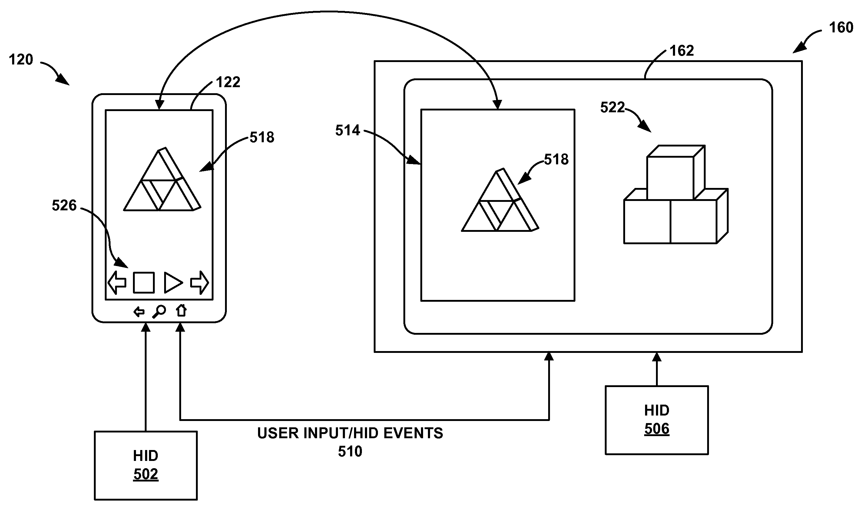
0020<figref idref="DRAWINGS">FIG. 5</figref> is a schematic diagram illustrating an example wireless communication between a source device and a sink device, according to aspects of this disclosure.
0021<figref idref="DRAWINGS">FIG. 6</figref> is a flow diagram illustrating an example method that may enable a source device to communicate with a wireless sink device, according to aspects of this disclosure.
0022<figref idref="DRAWINGS">FIG. 7</figref> is a flow diagram illustrating an example method that may enable a wireless sink device to communicate with a source device, according to aspects of this disclosure.
DETAILED DESCRIPTION
0023Wireless display (WD) systems may include a wireless display (WD) source and one or more wireless display sinks. In general, a wireless display source (“source device”) may send audio video (AV) data to a wireless display sink (“sink device”), which may render the received AV data at a terminal device. The AV data, in some examples, may include a sequence of frames (or pictures) played in rapid succession, which may also include associated audio frames, although sometimes audio frames are not included.
0024In some cases, the source device may be prompted to respond to user inputs applied at a sink device. In such an interactive application, the user inputs applied at the sink device may be sent back to the source device. In one example, a reverse channel architecture may be implemented to enable the wireless display system to transmit the user inputs applied at the sink device to the source device. The reverse channel architecture may include upper layer messages for transporting user inputs and lower layer frames for negotiating user interface capabilities at the sink device and the source device.
0025The wireless display reverse channel may reside above the Internet Protocol (IP) transport layer between a wireless display sink and the wireless display source. To promote reliable transmission and in sequence delivery to user inputs, the wireless display reverse channel may be configured run on top of TCP/IP. In some cases, there may be a mismatch between the user input interfaces at a sink device and a source device. To resolve the problems induced by such a mismatch and to promote a good user experience under such circumstances, user input interface capability negotiations occur between a sink device and a source device.
0026Aspects of this disclosure relate to enabling a source device to share graphical content for rendering at a sink device. In addition, aspects of this disclosure relate to enabling a sink device to act as a second display for a source device. Aspects of this disclosure also relate to enabling a source device to offload an application being executed by the source device, such that the application is then executed by a sink device.
0027<figref idref="DRAWINGS">FIG. 1A</figref> is a block diagram illustrating an exemplary source/sink system <b>100</b> that may implement techniques of this disclosure. As shown in <figref idref="DRAWINGS">FIG. 1</figref>, system <b>100</b> includes source device <b>120</b> that communicates with sink device <b>160</b> via communication channel <b>150</b>. Source device <b>120</b> may include a memory that stores audio/video (AN) data <b>121</b>, display <b>122</b>, speaker <b>123</b>, audio/video encoder <b>124</b> (also referred to as encoder <b>124</b>), audio/video control module <b>125</b>, and transmitter/receiver (TX/RX) unit <b>126</b>. Sink device <b>160</b> may include display <b>162</b>, speaker <b>163</b>, audio/video decoder <b>164</b> (also referred to as decoder <b>164</b>), transmitter/receiver unit <b>166</b>, user input (UI) device <b>167</b>, and user input processing module (UIPM) <b>168</b>. The illustrated components constitute merely one example, and other examples may include fewer components than those illustrated or additional components.
0028In the example of <figref idref="DRAWINGS">FIG. 1</figref>, source device <b>120</b> can display the video portion of audio/video data <b>121</b> on display <b>122</b> and can output the audio portion of audio/video data <b>121</b> on speaker <b>122</b>. Audio/video data <b>121</b> may be stored locally on source device <b>120</b>, accessed from an external storage medium such as a file server, Blu-ray disc, or DVD, or may be streamed to source device <b>120</b> via a network connection such as the internet. In some instances audio/video data <b>121</b> may be captured in real-time via a camera and microphone of source device <b>120</b>. Audio/video data <b>121</b> may include multimedia content such as movies, television shows, or music, but may also include real-time content generated by source device <b>120</b>. Such real-time content may for example be produced by applications running on source device <b>120</b>. Such real-time content may also include, in one example, a video frame of user input options available for a user to select. In some instances, audio/video data <b>121</b> may include video frames that are a combination of different types of content, such as a video frame of a movie or TV program that has user input options overlaid the frame of video.
0029In addition to rendering audio/video data <b>121</b> locally via display <b>122</b> and speaker <b>123</b>, audio/video encoder <b>124</b> of source device <b>120</b> can encode audio/video data <b>121</b>, and transmitter/receiver unit <b>126</b> can transmit the encoded data over communication channel <b>150</b> to sink device <b>160</b>. Transmitter/receiver unit <b>166</b> of sink device <b>160</b> receives the encoded data, and audio/video decoder <b>164</b> decodes the encoded data and outputs the decoded data via display <b>162</b> and speaker <b>163</b>. In this manner, the audio and video data being rendered by display <b>122</b> and speaker <b>12</b> can be simultaneously rendered by display <b>162</b> and speaker <b>163</b>. The audio data and video data may be arranged in frames, and the audio frames may be time-synchronized with the video frames when rendered.
0030Audio/video encoder <b>124</b> and audio/video decoder <b>164</b> may implement any number of audio and video compression standards, such as the ITU-T H.264 standard, alternatively referred to as MPEG-4, Part 10, Advanced Video Coding (AVC), or the newly emerging high efficiency video coding (HEVC) standard, sometimes called the H.265 standard. Generally speaking, audio/video decoder <b>164</b> is configured to perform the reciprocal coding operations of audio/video encoder <b>124</b>. Although not shown in <figref idref="DRAWINGS">FIG. 1</figref>, in some aspects, A/V encoder <b>124</b> and A/V decoder <b>164</b> may each be integrated with an audio encoder and decoder, and may include appropriate MUX-DEMUX units, or other hardware and software, to handle encoding of both audio and video in a common data stream or separate data streams.
0031Although, <figref idref="DRAWINGS">FIG. 1</figref> shows communication channel <b>150</b> carrying audio payload data and video payload data separately, it is to be understood that in some instances video payload data and audio payload data may be part of a common data stream. If applicable, MUX-DEMUX units may conform to the ITU H.223 multiplexer protocol, or other protocols such as the user datagram protocol (UDP). Audio/video encoder <b>124</b> and audio/video decoder <b>164</b> each may be implemented as one or more microprocessors, digital signal processors (DSPs), application specific integrated circuits (ASICs), field programmable gate arrays (FPGAs), discrete logic, software, hardware, firmware or any combinations thereof. Each of audio/video encoder <b>124</b> and audio/video decoder <b>164</b> may be included in one or more encoders or decoders, either of which may be integrated as part of a combined encoder/decoder (CODEC).
0032Display <b>122</b> and display <b>162</b> may comprise any of a variety of video output devices such as a cathode ray tube (CRT), a liquid crystal display (LCD), a plasma display, a light emitting diode (LED) display, an organic light emitting diode (OLED) display, or another type of display device. In these or other examples, the display device may be an emissive display or a transmissive display. Speaker <b>123</b> may comprise any of a variety of audio output devices such as headphones, a single-speaker system, a multi-speaker system, or a surround sound system. Additionally, although display <b>122</b> and speaker <b>123</b> are shown as part of source device <b>120</b> and display <b>162</b> and speaker <b>163</b> are shown as part of sink device <b>160</b>, source device <b>120</b> and sink device <b>160</b> may in fact be a system of devices. As one example, display <b>162</b> may be a television, speaker <b>163</b> may be a surround sound system, and decoder <b>164</b> may be part of an external box connected, either wired or wirelessly, to display <b>162</b> and speaker <b>163</b>. In other instances, sink device <b>160</b> may be a single device, such as a tablet computer or smartphone. In still other cases, source device <b>160</b> and sink device <b>120</b> are similar devices, e.g., both being smartphones, tablet computers, or the like. In this case, one device may operate as the source and the other may operate as the sink. These rolls may even be reversed in subsequent communication sessions.
0033Transmitter/receiver unit <b>126</b> and transmitter/receiver unit <b>166</b> may each include various mixers, filters, amplifiers and other components designed for signal modulation, as well as one or more antennas and other components designed for transmitting and receiving data. Communication channel <b>150</b> generally represents any suitable communication medium, or collection of different communication media, for transmitting video data from source device <b>120</b> to sink device <b>160</b>. Communication channel <b>150</b> is usually a relatively short-range communication channel, similar to WiFi, Bluetooth, or the like. However, communication channel <b>150</b> is not necessarily limited in this respect, and may comprise any wireless or wired communication medium, such as a radio frequency (RF) spectrum or one or more physical transmission lines, or any combination of wireless and wired media. In other examples, communication channel <b>150</b> may even form part of a packet-based network, such as a local area network, a wide-area network, or a global network such as the Internet. Source device <b>120</b> and sink device <b>160</b> may communicate over communication channel using a communications protocol such as a standard from the IEEE 802.11 family of standards.
0034In addition to decoding and rendering data received from source device <b>120</b>, sink device <b>160</b> can also receive user inputs from user input device <b>167</b>. User input device <b>167</b> may, for example, be a keyboard, mouse, trackball or track pad, touch screen, voice command recognition module, another type of human device interface (HDI) unit or device, or any other such user input device. User input processing module <b>168</b>, formats user input commands received by user input device <b>167</b> into a data packet structure that source device <b>120</b> is capable of interpreting. Such data packets are transmitted by transmitter/receiver <b>166</b> to source device <b>120</b> over communication channel <b>150</b>. Transmitter/receiver unit <b>126</b> receives the data packets, and A/V control module parses the data packets to interpret the user input command that was received by user input device <b>167</b>. Based on the command received in the data packet, A/V control module <b>125</b> can change the content being encoded and transmitted. In this manner, a user of sink device <b>160</b> can control the audio payload data and video payload data being transmitted by source device <b>120</b> remotely and without directly interacting with source device <b>120</b>. Examples of the types of commands a user of sink device <b>160</b> may transmit to source device <b>120</b> include commands for rewinding, fast forwarding, pausing, and playing audio and video data, as well as commands for zooming, rotating, scrolling, and so on. Users may also make selections, from a menu of options for example, and transmit the selection back to source device <b>120</b>. Commands may be application-specific or platform-specific, or may comprise general commands applicable to multiple platforms or multiple applications.
0035Source device <b>120</b> can respond to user inputs applied at sink device <b>160</b>. In such an interactive application setting, the user inputs applied at sink device <b>160</b> may be sent back to the wireless display source over communication channel <b>150</b>. In one example, a reverse channel architecture, also referred to as a user interface back channel (UIBC) may be implemented to enable sink device <b>160</b> to transmit the user inputs applied at sink device <b>160</b> to source device <b>120</b>. The reverse channel architecture may include upper layer messages for transporting user inputs and lower layer frames for negotiating user interface capabilities at sink device <b>160</b> and source device <b>120</b>. The UIBC may reside over the Internet Protocol (IP) transport layer between sink device <b>160</b> and source device <b>120</b>. To promote reliable transmission and in sequence delivery of data packets containing user input data, UIBC may be configured run on top of other packet-based communication protocols such as the transmission control protocol/internet protocol (TCP/IP) or the user datagram protocol (UDP).
0036In some cases, there may be a mismatch between the user input interfaces located at source device <b>120</b> and sink device <b>160</b>. To resolve the potential problems created by such a mismatch and to promote a good user experience under such circumstances, user input interface capability negotiation may occur between source device <b>120</b> and sink device <b>160</b> prior to establishing a communication session.
0037The UIBC may be designed to transport various types of user input data, including cross-platform user input data. For example, source device <b>120</b> may run the iOS® operating system, while sink device <b>160</b> runs another operating system such as Android® or Windows®. Regardless of platform, UIPM <b>168</b> can encapsulate received user input in a form understandable to A/V control module <b>125</b>. A number of different types of user input formats may be supported by the UIBC so as to allow many different types of source and sink devices to exploit the protocol. Generic input formats may be defined, and platform specific input formats may both be supported, thus providing flexibility in the manner in which user input can be communicated between source device <b>120</b> and sink device <b>160</b> by the UIBC.
0038In the example of <figref idref="DRAWINGS">FIG. 1</figref>, source device <b>120</b> may comprise a smartphone, tablet computer, laptop computer, desktop computer, WiFi enabled television, or any other device capable of transmitting audio and video data. Sink device <b>160</b> may likewise comprise a smartphone, tablet computer, laptop computer, desktop computer, WiFi enabled television, or any other device capable of receiving audio and video data and receiving user input data. In some instances, sink device <b>160</b> may include a system of devices, such that display <b>162</b>, speaker <b>163</b>, UI device <b>167</b>, and A/V encoder <b>164</b> all parts of separate but interoperative devices. Source device <b>120</b> may likewise be a system of devices rather than a single device. In many cases, source device <b>120</b> and sink device <b>160</b> may be similar or identical device, with one device operating as the source and the other operating as the sink. Moreover, these roles may be reversed in different communication sessions.
0039Aspects of this disclosure relate to enabling source device <b>120</b> to share graphical content for rendering at sink device <b>160</b>. In addition, aspects of this disclosure relate to enabling sink device <b>160</b> to act as a second display for source device <b>120</b>. Aspects of this disclosure also relate to enabling source device <b>120</b> to offload an application being executed by source device <b>120</b>, such that the application is then executed by sink device <b>160</b>.
0040To share graphical content, source device <b>120</b> may initially establish a wireless connection with sink device <b>160</b>. In some examples, sink device <b>160</b> may include a Graphics Processing Unit (GPU) for rendering graphics data. Accordingly, in response to establishing the wireless connection, source device <b>120</b> may receive information that describes the GPU of sink device <b>160</b> (e.g., such as information describing GPU capabilities). As source device <b>120</b> renders graphical content, source device <b>120</b>, using techniques of this disclosure, may generate configuration data that represents graphical objects included in the graphical content.
0041In general, configuration data may represent graphical objects included in the graphical content without providing actual pixel-level data (e.g., pixel values of a particular colorspace). Graphical objects may include, for example, objects comprised of one or more geometric primitives that form a shape for display. Configuration data may require fewer bits than pixel-level display data to represent graphical content. In some examples, configuration data may be similar to OpenGL instructions or instructions of another GPU language. The configuration data may also include graphical commands to modify or manipulate graphical objects. Thus, instead of mirroring display data at a pixel-level, graphical objects (e.g., overlays) and/or graphics commands may be extracted and extended over a wireless connection from source device <b>120</b> to sink device <b>160</b>.
0042According to the techniques of this disclosure, source device <b>120</b> may send configuration data to sink device <b>160</b> rather than pixel-level display data. Upon receiving the configuration data, sink device <b>160</b> (e.g., the GPU of sink device <b>160</b>) may use the configuration data to render graphical content at sink device <b>160</b>. In this way, the source/sink system can leverage the rendering capabilities of sink device <b>160</b>, rather than relaying solely on source device <b>120</b> to process and produce all pixel-level data.
0043In some examples, source device <b>120</b> may also generate configuration data that includes commands to modify or manipulate the graphical objects at sink device <b>160</b>. For instance, if a user provides a user input to source device <b>120</b> to increase the size of a graphical object, source device <b>120</b>, using techniques of the disclosure, may generate configuration data that describes the increase in size of the graphical object. The configuration may be sent to sink device <b>160</b>, which may use the configuration data to modify and/or manipulate the corresponding graphical object (e.g., increase the size of the graphical object). That is, upon receiving the configuration data from source device <b>120</b>, the GPU of sink device <b>160</b> may use the configuration data to modify graphical content rendered at sink device <b>160</b>. According to aspects of this disclosure, as noted above, the configuration data describing the modification to the graphical content may require fewer bits than updated pixel-level display data to represent changes to graphical content.
0044According to some examples, source device <b>120</b> may generate configuration data based on the capabilities of sink device <b>160</b>. That is, for example, source device <b>120</b> may generate configuration data that is interpretable by and/or specific to the capabilities and design of the GPU of sink device <b>160</b>. Thus, source device <b>120</b> may share more of the rendering load with sink device <b>160</b> having relatively powerful rendering capabilities than sink device <b>160</b> having relatively simplistic rendering capabilities.
0045In some examples, techniques of the present disclosure may enable source device <b>120</b> and sink devices <b>160</b> to operate in various different modes. For instance, one mode may cause source device <b>120</b> to generate and send configuration data to sink device <b>160</b>, while in a different mode source device <b>120</b> may send pixel-level display data. In another mode, source device <b>120</b> may send a combination of pixel-level display data for some graphical objects and configuration data for other graphical objects.
0046In this way, aspects of this disclosure may be implemented to conserve power at source device <b>120</b> (e.g., due to a reduced computational load associated with rendering pixel-level data). In addition, aspects of this disclosure may be implemented to use less bandwidth, as the configuration data typically comprises fewer bits than pixel-level data. In some examples, latency associated with rendering and/or modifying graphical content at sink device <b>160</b> (from source device <b>120</b>) may also be reduced.
0047Moreover, the techniques of the disclosure may provide improved display quality of graphical content shared between source device <b>120</b> and sink device <b>160</b> in situations in which source device <b>120</b> and sink device <b>160</b> have different rendering capabilities. That is, in some instances, source device <b>120</b> may have a lower display resolution than sink device <b>160</b>. In an example for purposes of illustration, source device <b>120</b> may be a mobile device (e.g., a tablet or smartphone), while sink device <b>160</b> may be a larger television (e.g., a liquid crystal display (LCD) or other television). In such an example, if sink device <b>160</b> receives pixel-level display data from source device <b>120</b>, sink device <b>160</b> may be required to upscale or otherwise modify the pixel-level graphical content to the native resolution of sink device <b>160</b>. According to aspects of this disclosure, sink device <b>160</b> may instead receive configuration data (e.g., rather than pixel-level data). Thus, sink device <b>160</b> may use the configuration data to generate graphical content in the native resolution of sink device <b>160</b>, thereby providing a higher quality display of the graphical content.
0048As noted above, aspects of this disclosure also relate to enabling sink device <b>160</b> to act as a second display, which may also be referred to as a “secondary display” for source device <b>120</b>. That is, rather than mirroring all content from source device <b>120</b> to sink device <b>160</b>, aspects of this disclosure relate to sharing some content between source device <b>120</b> and sink device <b>160</b> such that sink device <b>160</b> may display certain graphical objects not displayed at source device <b>120</b>. In some examples, a user may select one or more graphical objects being rendered at source device <b>120</b> to be shared for rendering on sink device <b>160</b>. In other examples, an application may automatically determine one or more graphical objects being rendered at source device <b>120</b> to be shared for rendering on sink device <b>160</b>.
0049In some examples, source device <b>120</b> may map a display resolution of source device <b>120</b> to sink device <b>160</b>. For example, when source device <b>120</b> and sink device <b>160</b> initially communicate, the devices may exchange display resolution information. Accordingly, source device <b>120</b> may select different sets of graphical objects for rendering at sink device <b>160</b> based on the resolution of sink device <b>160</b>. For instance, if the resolution of sink device <b>160</b> is relatively high, source device <b>120</b> may send a first set of graphical objects to sink device <b>160</b>. If, however, the resolution of sink device <b>160</b> is relatively low, source device <b>120</b> may send a second set of graphical objects to sink device <b>160</b> that includes fewer graphical objects than the first set. More generally, using techniques of the disclosure, source device <b>120</b> may determine, based on any capability (e.g., resolution) of sink device <b>160</b>, which graphical elements are sent from source device <b>120</b> to sink device <b>160</b>.
0050In one example, source device <b>120</b> (e.g., a mobile device such as a tablet or smartphone) may render video data associated with a movie using a movie player application being executed by source device <b>120</b>. The user may provide user input that causes source device <b>120</b> to share video data representing the movie on sink device <b>160</b> (e.g., a LCD television). The user input may additionally cause graphical controls of the movie player to be rendered at source device <b>120</b>, without being rendered at sink device <b>160</b>. In this way, techniques of the present disclosure may enable source device <b>120</b> to render a first portion of graphical content on source device <b>120</b> and a second portion of the graphical content on sink device <b>160</b>. To render the second portion of the graphical content at sink device <b>160</b>, source device <b>120</b> may generate configuration data usable by sink device <b>160</b> to render the graphical content. By sending the configuration data to sink device <b>160</b>, the second portion of graphical content may be rendered at sink device <b>160</b>.
0051As noted above, aspects of this disclosure also relate to enabling source device <b>120</b> to offload an application being executed by source device <b>120</b>, such that the application is then executed by sink device <b>160</b>. For example, source device <b>120</b> may be initially executing a particular application. The user may then provide a user input to offload execution of the application onto sink device <b>160</b>. In such examples, source device <b>120</b> may request certain information from sink device <b>160</b> regarding the capabilities of sink device <b>160</b>. In response to the request, sink device <b>160</b> may send information to source device <b>120</b> that indicates capabilities of sink device <b>160</b>. For instance, capabilities may include the operating system of sink device <b>160</b>, applications installed on sink device <b>160</b>, and data indicating the computing performing of sink device <b>160</b>.
0052In an example, in response to a request to offload an application to sink device <b>160</b>, source device <b>120</b> may determine that another instance of the application running on source device <b>120</b> is also stored on sink device <b>160</b>. In such examples, source device <b>120</b> may send information to sink device <b>160</b> that identifies the application. The information may further include data previously used by the application on source device <b>120</b> that will be used by the application on sink device <b>160</b>. Upon receiving the application information, sink device <b>160</b> may execute the application on sink device <b>160</b>. That is, sink device <b>160</b> may launch the application at sink device <b>160</b>. In addition, sink device <b>160</b> may use the application information received from source device <b>120</b> to transition to the same state as the application being executed by source device <b>120</b>.
0053In some examples, one or more processes associated with offloading applications or other processes from source device <b>120</b> to sink device <b>160</b> may be performed automatically. For example, rather, source device <b>120</b> and sink device <b>160</b> may exchange information regarding the capabilities of sink device <b>160</b> automatically. That is, in an example, sink device <b>160</b> may send information regarding the capabilities of sink device <b>160</b> automatically upon establishing a connection with source device <b>120</b>. Additionally or alternatively, rather than waiting for a request from a user to offload an application to sink device <b>160</b>, source device <b>120</b> may automatically may an application offload determination. For example, upon establishing a connection and determining the capabilities of sink device <b>160</b>, source device <b>120</b> may offload certain applications or other processes that source device <b>120</b> determines that sink device <b>160</b> has the ability to execute.
0054In some examples, source device <b>120</b> may communicate with more than one sink device <b>160</b> (e.g., as shown and described, for example, with respect to <figref idref="DRAWINGS">FIG. 1B</figref>). That is, for example, user input may be received by source device <b>120</b> from multiple sink devices <b>160</b> to modify graphical content rendered by source device <b>120</b>. Consequently, when events representing the user inputs are transported from multiple sink devices <b>160</b> to source device <b>120</b>, synchronization issues may arise. For instance, display data rendered by source device <b>120</b> may be sent to one or more sink devices <b>160</b> for rendering. A user may provide a user input from a first sink device <b>160</b>, which may generate an event that is sent to source device <b>120</b>. Prior to source device <b>120</b> receiving the event, another user may provide a user input at source device <b>120</b>. In such examples, to facilitate such communication, timestamps may be applied to each user input. The timestamps may be used to synchronize the manner in which user inputs are applied to the display data rendered by source device <b>120</b>. For instance, a first user input with an earlier timestamp may be applied prior to a second user input with a later timestamp.
0055<figref idref="DRAWINGS">FIG. 1B</figref> is a block diagram illustrating an exemplary source/sink system <b>101</b> that may implement techniques of this disclosure. Source/sink system <b>101</b> includes source device <b>120</b>, sink device <b>160</b>A, and sink device <b>160</b>B (collectively, sink devices <b>160</b>). In some examples, source device <b>120</b> and sink devices <b>160</b> may function and operate in the manner described above with respect to <figref idref="DRAWINGS">FIG. 1A</figref>. That is, in a similar manner as described with respect to sink device <b>160</b> shown in <figref idref="DRAWINGS">FIG. 1A</figref>, sink devices <b>160</b>A and <b>160</b>B may receive audio and video data from source device <b>120</b>. For example, in some configurations, audio and video output at source device <b>120</b> may be simultaneously output at sink device <b>160</b>A and sink device <b>160</b>B.
0056Thus, in general, it should be understood that the techniques of this disclosure may be extended to support multiple source and/or sink devices. That is, according to aspects of this disclosure, as described above with respect to <figref idref="DRAWINGS">FIG. 1A</figref>, source device <b>120</b> may share graphical content for rendering at any or all of sink devices <b>160</b>. Additionally or alternatively, any or all of sink devices <b>160</b> may act as secondary displays for source device <b>120</b>. Additionally or alternatively, source device <b>120</b> may offload one or more applications being executed by source device <b>120</b> to sink device <b>160</b>A, sink device <b>160</b>B, or any other sink device in communication with source device <b>120</b>.
0057While sink device <b>160</b>A and sink device <b>160</b>B have been assigned like numerals, it should be understood that, in some examples, sink device <b>160</b>A and sink device <b>160</b>B may have different capabilities and/or perform different functions. For example, in some configurations, sink device <b>160</b>A may be a primary sink device and sink device <b>160</b>B may be a secondary sink device. In such a configuration, sink device <b>160</b>A and sink device <b>160</b>B may be coupled, and sink device <b>160</b>A may display video data while sink device <b>160</b>B outputs corresponding audio data.
0058<figref idref="DRAWINGS">FIG. 2</figref> is a block diagram showing one example of a source device <b>220</b>, such as source device <b>120</b> in <figref idref="DRAWINGS">FIG. 1</figref>. Source device <b>220</b> includes local display <b>222</b>, local speaker <b>223</b>, processors <b>231</b>, memory <b>232</b>, transport module <b>233</b>, and wireless modem <b>234</b>. As shown in <figref idref="DRAWINGS">FIG. 2</figref>, source <b>220</b> device may include one or more processors (i.e. processor <b>231</b>) that encode and/or decode A/V data for transport, storage, and display. The A/V data may for example be stored at memory <b>232</b>. Memory <b>232</b> may store an entire A/V file, or may comprise a smaller buffer that simply stores a portion of an A/V file, e.g., streamed from another device or source. Transport module <b>233</b> may process encoded A/V data for network transport. For example, encoded A/V data may be processed by multimedia processors <b>231</b> and encapsulated by transport module <b>233</b> into Network Access Layer (NAL) units for communication across a network. The NAL units may be sent by wireless modem <b>234</b> to a sink device via a network connection.
0059Source device <b>220</b> may also locally process and display A/V data. In particular display processor <b>235</b> may process video data to be displayed on local display <b>222</b>, audio processor <b>236</b> may process audio data for output on speaker <b>223</b>.
0060As described above with reference to source device <b>120</b> of <figref idref="DRAWINGS">FIG. 1</figref>, source device <b>220</b> may also receive user input commands from a sink device. In this manner, wireless modem <b>234</b> of source device <b>220</b> receives encapsulated data packets, such as NAL units, and sends the encapsulated data units to transport unit <b>233</b> for decapsulation. For instance, transport unit <b>233</b> may extract data packets from the NAL units, and processor <b>231</b> can parse the data packets to extract the user input commands. Based on the user input commands, processor <b>231</b> can adjust the encoded A/V data being transmitted by source device <b>220</b> to a sink device.
0061Processor <b>231</b> of <figref idref="DRAWINGS">FIG. 2</figref> generally represents any of a wide variety of processors, including but not limited to one or more digital signal processors (DSPs), general purpose microprocessors, application specific integrated circuits (ASICs), field programmable logic arrays (FPGAs), other equivalent integrated or discrete logic circuitry, or some combination thereof. Memory <b>232</b> of <figref idref="DRAWINGS">FIG. 2</figref> may comprise any of a wide variety of volatile or non-volatile memory, including but not limited to random access memory (RAM) such as synchronous dynamic random access memory (SDRAM), read-only memory (ROM), non-volatile random access memory (NVRAM), electrically erasable programmable read-only memory (EEPROM), FLASH memory, and the like, Memory <b>232</b> may comprise a computer-readable storage medium for storing audio/video data, as well as other kinds of data. Memory <b>232</b> may additionally store instructions and program code that are executed by processor <b>231</b> as part of performing the various techniques described in this disclosure.
0062<figref idref="DRAWINGS">FIG. 3</figref> shows an example of a sink device <b>360</b>, such as sink device <b>160</b> in <figref idref="DRAWINGS">FIG. 1</figref>. Sink device <b>360</b> includes processor <b>331</b>, memory <b>332</b>, transport unit <b>333</b>, wireless modem <b>334</b>, display processor <b>335</b>, local display <b>362</b>, audio processor <b>336</b>, speaker <b>363</b>, and touch display interface <b>336</b>. Sink device <b>360</b> receives at wireless modem <b>334</b> encapsulated data units sent from a source device. Transport unit <b>333</b> can decapsulate the encapsulated data units. For instance, transport unit <b>333</b> may extract encoded video data from the encapsulated data units and send the encoded A/V data to processor <b>331</b> to be decoded and rendered for output. Display processor <b>335</b> may process decoded video data to be displayed on local display <b>362</b>, and audio processor <b>336</b> may process decoded audio data for output on speaker <b>363</b>.
0063In addition to rendering audio and video data, sink device <b>360</b> can also receive user input through touch display interface <b>336</b>. Although the example of <figref idref="DRAWINGS">FIG. 3</figref> utilizes a touch display interface as an example input device, other input devices such as keyboards, mouse, or voice command modules are all compatible with the techniques of this disclosure. User input received through touch display interface <b>336</b> can be processed by processor <b>331</b>. This processing may include generating data packets that included the received user input command in accordance with the techniques described in this disclosure. Once generated, transport module <b>333</b> may process the data packets for network transport to a wireless source device over a UIBC.
0064Processor <b>331</b> of <figref idref="DRAWINGS">FIG. 3</figref> may comprise one or more of a wide range of processors, such as one or more digital signal processors (DSPs), general purpose microprocessors, application specific integrated circuits (ASICs), field programmable logic arrays (FPGAs), other equivalent integrated or discrete logic circuitry, or some combination thereof. Memory <b>332</b> of <figref idref="DRAWINGS">FIG. 3</figref> may comprise any of a wide variety of volatile or non-volatile memory, including but not limited to random access memory (RAM) such as synchronous dynamic random access memory (SDRAM), read-only memory (ROM), non-volatile random access memory (NVRAM), electrically erasable programmable read-only memory (EEPROM), FLASH memory, and the like, Memory <b>232</b> may comprise a computer-readable storage medium for storing audio/video data, as well as other kinds of data. Memory <b>332</b> may additionally store instructions and program code that are executed by processor <b>331</b> as part of performing the various techniques described in this disclosure.
0065<figref idref="DRAWINGS">FIG. 4</figref> shows a block diagram of an example transmitter system <b>410</b> and receiver system <b>450</b>, which may be used by transmitter/receiver <b>126</b> and transmitter/receiver <b>166</b> of <figref idref="DRAWINGS">FIG. 1</figref> for communicating over communication channel <b>150</b>. At transmitter system <b>410</b>, traffic data for a number of data streams is provided from a data source <b>412</b> to a transmit (TX) data processor <b>414</b>. Each data stream may be transmitted over a respective transmit antenna. TX data processor <b>414</b> formats, codes, and interleaves the traffic data for each data stream based on a particular coding scheme selected for that data stream.
0066The coded data for each data stream may be multiplexed with pilot data using orthogonal frequency division multiplexing (OFDM) techniques. A wide variety of other wireless communication techniques may also be used, including but not limited to time division multi access (TDMA), frequency division multi access (FDMA), code division multi access (CDMA), or any combination of OFDM, FDMA, TDMA and/or CDMA.
0067Consistent with <figref idref="DRAWINGS">FIG. 4</figref>, the pilot data is typically a known data pattern that is processed in a known manner and may be used at the receiver system to estimate the channel response. The multiplexed pilot and coded data for each data stream is then modulated (e.g., symbol mapped) based on a particular modulation scheme (e.g., Binary Phase Shift Keying (BPSK), Quadrature Phase Shift Keying (QPSK), M-PSK, or M-QAM (Quadrature Amplitude Modulation), where M may be a power of two) selected for that data stream to provide modulation symbols. The data rate, coding, and modulation for each data stream may be determined by instructions performed by processor <b>430</b> which may be coupled with memory <b>432</b>.
0068The modulation symbols for the data streams are then provided to a TX MIMO processor <b>420</b>, which may further process the modulation symbols (e.g., for OFDM). TX MIMO processor <b>420</b> can then provides NT modulation symbol streams to NT transmitters (TMTR) <b>422</b><i>a </i>through <b>422</b><i>t</i>. In certain aspects, TX MIMO processor <b>420</b> applies beamforming weights to the symbols of the data streams and to the antenna from which the symbol is being transmitted.
0069Each transmitter <b>422</b> may receive and process a respective symbol stream to provide one or more analog signals, and further conditions (e.g., amplifies, filters, and upconverts) the analog signals to provide a modulated signal suitable for transmission over the MIMO channel. NT modulated signals from transmitters <b>422</b><i>a </i>through <b>422</b><i>t </i>are then transmitted from NT antennas <b>424</b><i>a </i>through <b>424</b><i>t</i>, respectively.
0070At receiver system <b>450</b>, the transmitted modulated signals are received by NR antennas <b>452</b><i>a </i>through <b>452</b><i>r </i>and the received signal from each antenna <b>452</b> is provided to a respective receiver (RCVR) <b>454</b><i>a </i>through <b>454</b><i>r</i>. Receiver <b>454</b> conditions (e.g., filters, amplifies, and downconverts) a respective received signal, digitizes the conditioned signal to provide samples, and further processes the samples to provide a corresponding “received” symbol stream.
0071A receive (RX) data processor <b>460</b> then receives and processes the NR received symbol streams from NR receivers <b>454</b> based on a particular receiver processing technique to provide NT “detected” symbol streams. The RX data processor <b>460</b> then demodulates, deinterleaves and decodes each detected symbol stream to recover the traffic data for the data stream. The processing by RX data processor <b>460</b> is complementary to that performed by TX MIMO processor <b>420</b> and TX data processor <b>414</b> at transmitter system <b>410</b>.
0072A processor <b>470</b> that may be coupled with a memory <b>472</b> periodically determines which pre-coding matrix to use. The reverse link message may comprise various types of information regarding the communication link and/or the received data stream. The reverse link message is then processed by a TX data processor <b>438</b>, which also receives traffic data for a number of data streams from a data source <b>436</b>, modulated by a modulator <b>480</b>, conditioned by transmitters <b>454</b><i>a </i>through <b>454</b><i>r</i>, and transmitted back to transmitter system <b>410</b>.
0073At transmitter system <b>410</b>, the modulated signals from receiver system <b>450</b> are received by antennas <b>424</b>, conditioned by receivers <b>422</b>, demodulated by a demodulator <b>440</b>, and processed by a RX data processor <b>442</b> to extract the reserve link message transmitted by the receiver system <b>450</b>. Processor <b>430</b> then determines which pre-coding matrix to use for determining the beamforming weights then processes the extracted message.
0074<figref idref="DRAWINGS">FIG. 5</figref> is a schematic diagram illustrating an example wireless communication between a source device and a sink device, according to aspects of this disclosure. While <figref idref="DRAWINGS">FIG. 5</figref> is described with respect to source device <b>120</b> and sink device <b>160</b> (<figref idref="DRAWINGS">FIG. 1A</figref>), it should be understood that the techniques of <figref idref="DRAWINGS">FIG. 5</figref> may be performed by a variety of devices, including other source and sink devices.
0075In the example shown in <figref idref="DRAWINGS">FIG. 5</figref>, display <b>122</b> of source device <b>120</b> is configured as a touch sensitive display. For example, display <b>122</b> may be a capacitive, resistive, or other type of touch panel that allows a user to provide user input to source device <b>120</b>.
0076Thus, when a user provides a user input at display <b>122</b>, source device <b>120</b> may generate one or more events that correspond to the user input. In some examples, display <b>122</b> may be designed to simultaneously recognize touches at more than one point, a feature commonly referred to as “multi-touch.” Multi-touch displays may separately identify and interpret touches in different areas of the screen. In addition to display <b>122</b>, according to the example shown in <figref idref="DRAWINGS">FIG. 5</figref>, source device <b>120</b> may receive input from another source, such as one or more human interface devices (HIDs) <b>502</b>. Example, HIDs <b>502</b> include a keyboard, mouse, trackball or track pad, touch screen, voice command recognition module, or any other such user input device.
0077In some examples, display <b>162</b> of sink device <b>160</b> may also be touch sensitive. That is, for example, display <b>162</b> may also be a capacitive, resistive, or other type of touch panel that allows a user to provide user input to source device <b>120</b>. In some examples, display <b>162</b> may comprise a multi-touch display. Moreover, as shown in the example of <figref idref="DRAWINGS">FIG. 5</figref>, sink device <b>160</b> may also receive input from another source, such as one or more human interface devices (HIDs) <b>506</b>.
0078According to aspects of this disclosure, source device <b>120</b> may send one or more events to sink device <b>160</b> (represented by line <b>510</b>). For example, source device <b>120</b> may send certain events associated with user input at source device <b>120</b> to sink device <b>160</b>. That is, the events may correspond to user input provided to display <b>122</b> and/or provided via HIDs <b>502</b>. Likewise, in some examples, sink device <b>160</b> may send certain events associated with user input at sink device <b>160</b> to source device <b>120</b>. Such events may correspond to user input provided to display <b>162</b> and/or provided via HIDs <b>506</b>. In some examples, source device <b>120</b> may use Real-time Transport Protocol (RTP) and User Datagram Protocol (UDP) to send events to sink device <b>160</b>. In other examples, source device <b>120</b> may use Transmission Control Protocol (TCP) and Internet Protocol (IP) to send events to sink device <b>160</b>.
0079In some examples, sink device <b>160</b> may render data from source device <b>120</b> on only a portion of display <b>162</b> of sink device. That is, for example, sink device <b>160</b> may designate an area <b>514</b> in which to render graphical content <b>518</b> from source device <b>120</b>. In some examples, as described in greater detail below, graphical content <b>518</b> may be displayed on display <b>162</b> in the same or in a different resolution than on display <b>122</b>. Moreover, in some examples, sink device <b>160</b> may simultaneously render and display other graphical content <b>522</b> that is natively generated at sink device <b>160</b> on another portion of display <b>162</b>.
0080As shown in <figref idref="DRAWINGS">FIG. 5</figref>, according to some aspects of this disclosure, source device <b>120</b> may share graphical content <b>518</b> for rendering at sink device <b>160</b>. For example, source device <b>120</b> may, using techniques of this disclosure, generate configuration data that represents graphical objects included in the graphical content <b>518</b>. In general, as noted above, configuration data may represent graphical objects included in the graphical content without providing actual pixel data. Moreover, the configuration data may represent the graphical objects using fewer bits than the pixel data associated with the graphical objects. In some examples, configuration data may be similar to OpenGL instructions or instructions of another GPU language. Thus, to achieve a bit savings with respect to the number of bits that are sent from source device <b>120</b> to sink device <b>160</b>, source device <b>120</b> may send configuration data representing graphical content <b>518</b> to sink device <b>160</b> rather than pixel-level data. Upon receiving the configuration data, sink device <b>160</b> may use the configuration data to render the graphical content <b>518</b> at sink device <b>160</b>. That is, sink device <b>160</b> may use the configuration data to render pixel-level data (e.g., RGB values, YCbCr values, or the like) for display.
0081In some examples, source device <b>120</b> may also generate configuration data that includes commands to modify or manipulate graphical content <b>518</b> rendered at sink device <b>160</b>. For instance, if a user provides a user input to source device <b>120</b> (e.g., via display <b>122</b>) to increase the size of a graphical object, source device <b>120</b>, using techniques of the disclosure may generate configuration data that describes the increase in size. This configuration may be sent to sink device <b>160</b>, which may use the configuration data to modify and/or manipulate the corresponding graphical content <b>514</b>. That is, upon receiving the configuration data from source device <b>120</b>, sink device <b>160</b> may use the configuration data to increase the size of the graphical content <b>518</b>.
0082In another example, graphical content <b>518</b> may be associated with a motion picture or other video. In this example, source device <b>120</b> may render graphical content <b>518</b> using an application being executed by source device <b>120</b>. According to aspects of this disclosure, a user may provide user input that causes source device <b>120</b> to share graphical content <b>518</b> included in the video with sink device <b>160</b>. The user input may additionally cause graphical controls <b>526</b> of the application to be rendered at source device <b>120</b>, without being rendered at sink device <b>160</b>. In this way, techniques of the present disclosure may enable source device <b>120</b> to render a first portion of graphical content on source device <b>120</b> and a second portion of the graphical content on sink device <b>160</b>. To render the second portion of the graphical content at sink device <b>160</b>, source device <b>120</b> may generate configuration data usable by sink device <b>160</b> to render the graphical content. By sending the configuration data to sink device <b>160</b>, the second portion of graphical content may be rendered at sink device <b>160</b>.
0083Moreover, the techniques of the disclosure may provide improved display quality of graphical content shared between source device <b>120</b> and sink device <b>160</b> in situations in which source device <b>120</b> and sink device <b>160</b> have different rendering capabilities. In the example shown in <figref idref="DRAWINGS">FIG. 5</figref>, source device <b>120</b> may have a lower display resolution than sink device <b>160</b>. According to aspects of this disclosure, sink device <b>160</b> may receive configuration data from source device <b>120</b>, and utilize the configuration data to generate graphical content <b>514</b> in the native resolution of sink device <b>160</b>. In this way, graphical content <b>514</b> may be displayed differently at sink device <b>160</b> than source device <b>120</b> (e.g., in a higher resolution, an alternative size, and the like).
0084<figref idref="DRAWINGS">FIG. 6</figref> is a flow diagram illustrating an example method that may enable a source device to generate configuration data usable by a sink device. While the method shown in <figref idref="DRAWINGS">FIG. 6</figref> may be described with respect to source device <b>120</b> and sink device <b>160</b> for purposes of explanation, it should be understood that the method of <figref idref="DRAWINGS">FIG. 6</figref> may be performed by a variety of devices, including other source and/or sink devices.
0085As shown in <figref idref="DRAWINGS">FIG. 6</figref>, source device <b>120</b> may initially determine that display data rendered by source device <b>120</b> comprises one or more displayable graphical objects (<b>600</b>). Graphical objects may include, for example, objects comprised of one or more geometric primitives that form a shape for display. Source device <b>120</b>, in response to determining an event, may select a set of the one or more graphical objects for rendering at sink device <b>160</b> (<b>602</b>). For example, an event may be generated in response to a user input. In another example, the event may be generated automatically by an application being executed by the source device <b>120</b>.
0086Source device <b>120</b> may further generate configuration data based at least in part on the set of the one or more graphical objects (<b>604</b>). In general, configuration data may represent graphical objects without including pixel-level data (e.g., pixel values). Configuration data may require fewer bits than pixel-level data to represent the graphical objects. In some examples, configuration data may be similar to OpenGL instructions or instructions of another GPU language.
0087According to aspects of this disclosure, the configuration data may be usable by sink device <b>160</b> to render representations of the graphical objects in the set of one or more graphical objects. In some examples, source device <b>120</b> may generate configuration data based on display parameters of sink device <b>160</b>. Display parameters may include, for example, display resolution, color bit depth, GPU type, or any other parameters that indicate display capabilities of sink device <b>160</b>. Thus, source device <b>120</b> may generate configuration data that is interpretable by and/or specific to the capabilities and design of a GPU of sink device <b>160</b>. In some examples, source device <b>120</b> may share more of the rendering load with sink device <b>160</b> having relatively powerful rendering capabilities than sink device <b>160</b> having relatively simplistic rendering capabilities.
0088Source device <b>120</b> may generate any combination of configuration data and pixel-level data for transmission to sink device <b>160</b>. For example, source device <b>120</b> and sink device <b>160</b> may operate in various modes. One mode may cause source device <b>120</b> to generate only configuration data that represents graphical objects for transmission to sink device <b>160</b>. Another mode may cause source device <b>120</b> to generate only pixel-level display data for transmission to sink device <b>160</b>. In another mode, source device <b>120</b> may generate a combination of pixel-level data for some graphical objects and configuration data for other graphical objects for transmission to sink device <b>160</b>.
0089After generating the configuration data, source device <b>120</b> may send the configuration data to sink device <b>160</b> (<b>606</b>). As described in greater detail with respect to <figref idref="DRAWINGS">FIG. 7</figref> below, sink device <b>160</b> may utilize the configuration data to render the graphical objects represented by the configuration data.
0090<figref idref="DRAWINGS">FIG. 7</figref> is a flow diagram illustrating an example method that may enable a sink device to render representations of a set of graphical objects using configuration data from a source device. While the method shown in <figref idref="DRAWINGS">FIG. 7</figref> may be described with respect to source device <b>120</b> and sink device <b>160</b> for purposes of explanation, it should be understood that the method of <figref idref="DRAWINGS">FIG. 7</figref> may be performed by a variety of devices, including other source and/or sink devices.
0091As shown in <figref idref="DRAWINGS">FIG. 7</figref>, sink device <b>160</b> may receive configuration data from source device <b>120</b> that is usable by sink device <b>160</b> to render representations of a set of graphical objects (<b>700</b>). As noted above, configuration data may represent graphical objects without including pixel-level data (e.g., pixel values), and may require fewer bits than pixel-level data to represent the graphical objects.
0092In some examples, sink device <b>160</b> may render the representations of the set of graphical objects using the configuration data (<b>702</b>). That is, for example, sink device <b>160</b> may interpret the configuration data to generate pixel-level data using the configuration data. In some examples, sink device <b>160</b> may render the representations based at least in part on one or more display parameters associated with the sink device <b>160</b> (<b>702</b>). Display parameters may include display resolution, color bit depth, GPU type, or any other parameters that indicate display capabilities of sink device <b>160</b>.
0093In one or more examples, the functions described may be implemented in hardware, software, firmware, or any combination thereof. If implemented in software, the functions may be stored on or transmitted over as one or more instructions or code on a computer-readable medium and executed by a hardware-based processing unit. Computer-readable media may include computer-readable storage media, which corresponds to a tangible medium such as data storage media, or communication media including any medium that facilitates transfer of a computer program from one place to another, e.g., according to a communication protocol. In this manner, computer-readable media generally may correspond to (1) tangible computer-readable storage media which is non-transitory or (2) a communication medium such as a signal or carrier wave. Data storage media may be any available media that can be accessed by one or more computers or one or more processors to retrieve instructions, code and/or data structures for implementation of the techniques described in this disclosure. A computer program product may include a computer-readable medium.
0094By way of example, and not limitation, such computer-readable storage media can comprise RAM, ROM, EEPROM, CD-ROM or other optical disk storage, magnetic disk storage, or other magnetic storage devices, flash memory, or any other medium that can be used to store desired program code in the form of instructions or data structures and that can be accessed by a computer. Also, any connection is properly termed a computer-readable medium. For example, if instructions are transmitted from a website, server, or other remote source using a coaxial cable, fiber optic cable, twisted pair, digital subscriber line (DSL), or wireless technologies such as infrared, radio, and microwave, then the coaxial cable, fiber optic cable, twisted pair, DSL, or wireless technologies such as infrared, radio, and microwave are included in the definition of medium. It should be understood, however, that computer-readable storage media and data storage media do not include connections, carrier waves, signals, or other transient media, but are instead directed to non-transient, tangible storage media. Disk and disc, as used herein, includes compact disc (CD), laser disc, optical disc, digital versatile disc (DVD), floppy disk and blu-ray disc where disks usually reproduce data magnetically, while discs reproduce data optically with lasers. Combinations of the above should also be included within the scope of computer-readable media.
0095Instructions may be executed by one or more processors, such as one or more digital signal processors (DSPs), general purpose microprocessors, application specific integrated circuits (ASICs), field programmable logic arrays (FPGAs), or other equivalent integrated or discrete logic circuitry. Accordingly, the term “processor,” as used herein may refer to any of the foregoing structure or any other structure suitable for implementation of the techniques described herein. In addition, in some aspects, the functionality described herein may be provided within dedicated hardware and/or software modules configured for encoding and decoding, or incorporated in a combined codec. Also, the techniques could be fully implemented in one or more circuits or logic elements.
0096The techniques of this disclosure may be implemented in a wide variety of devices or apparatuses, including a wireless handset, an integrated circuit (IC) or a set of ICs (e.g., a chip set). Various components, modules, or units are described in this disclosure to emphasize functional aspects of devices configured to perform the disclosed techniques, but do not necessarily require realization by different hardware units. Rather, as described above, various units may be combined in a codec hardware unit or provided by a collection of interoperative hardware units, including one or more processors as described above, in conjunction with suitable software and/or firmware.
0097Various examples have been described. These and other examples are within the scope of the following claims.
Contents5
9 sheets
Sheet 1 Sheet 2 Sheet 3 Sheet 4 Sheet 5 Sheet 6 Sheet 7 Sheet 8 Sheet 9
Every citation, both ways
| Document | Relation | Office | Cited during |
|---|---|---|---|
| US12346624B2 | Cited by | United States of America | Applicant |
| WO0184291A1 | Cites | World Intellectual Property Organization (WIPO) | Applicant |
| WO0210942A1 | Cites | World Intellectual Property Organization (WIPO) | Applicant |
| WO0223825A1 | Cites | World Intellectual Property Organization (WIPO) | Applicant |
| WO0249314A2 | Cites | World Intellectual Property Organization (WIPO) | Applicant |
| WO03030451A1 | Cites | World Intellectual Property Organization (WIPO) | Applicant |
| WO03061240A1 | Cites | World Intellectual Property Organization (WIPO) | Applicant |
| WO03104834A2 | Cites | World Intellectual Property Organization (WIPO) | Applicant |
| KR100398610B1 | Cites | Republic of Korea | Applicant |
| CN101002453A | Cites | China | Applicant |
| CN101018330A | Cites | China | Applicant |
| CN101083825A | Cites | China | Applicant |
| CN101247249A | Cites | China | Applicant |
| CN101247250A | Cites | China | Applicant |
| CN101663640A | Cites | China | Applicant |
| EP1203080A2 | Cites | European Patent Office (EPO) | Applicant |
| EP1206080A1 | Cites | European Patent Office (EPO) | Applicant |
| EP1233326A2 | Cites | European Patent Office (EPO) | Applicant |
| EP1235392A1 | Cites | European Patent Office (EPO) | Applicant |
| EP1325591A1 | Cites | European Patent Office (EPO) | Applicant |
| EP1333373A1 | Cites | European Patent Office (EPO) | Search report |
| EP1385336A2 | Cites | European Patent Office (EPO) | Applicant |
| EP1423778A2 | Cites | European Patent Office (EPO) | Applicant |
| CN1437355A | Cites | China | Applicant |
| EP1507369A1 | Cites | European Patent Office (EPO) | Applicant |
| EP1517228A2 | Cites | European Patent Office (EPO) | Applicant |
| EP1550264A1 | Cites | European Patent Office (EPO) | Applicant |
| CN1561609A | Cites | China | Applicant |
| CN1592884A | Cites | China | Applicant |
| CN1596004A | Cites | China | Applicant |
| EP1653678A2 | Cites | European Patent Office (EPO) | Applicant |
| CN1656750A | Cites | China | Applicant |
| CN1662944A | Cites | China | Applicant |
| CN1774106A | Cites | China | Applicant |
| CN1832481A | Cites | China | Applicant |
| CN1893356A | Cites | China | Applicant |
| EP1944946A1 | Cites | European Patent Office (EPO) | Applicant |
| EP1959685A2 | Cites | European Patent Office (EPO) | Applicant |
| EP1959686A2 | Cites | European Patent Office (EPO) | Applicant |
| CN1983945A | Cites | China | Applicant |
| JP2000278320A | Cites | Japan | Applicant |
| JP2000354031A | Cites | Japan | Applicant |
| JP2001034250A | Cites | Japan | Applicant |
| JP2001282673A | Cites | Japan | Applicant |
| JP2001352533A | Cites | Japan | Applicant |
| US2002007494A1 | Cites | United States of America | Applicant |
| US2002035621A1 | Cites | United States of America | Applicant |
| JP2002064725A | Cites | Japan | Applicant |
| US2002097718A1 | Cites | United States of America | Applicant |
| JP2002142210A | Cites | Japan | Applicant |
| JP2002165248A | Cites | Japan | Applicant |
| JP2002262341A | Cites | Japan | Applicant |
| JP2002330381A | Cites | Japan | Applicant |
| US2003031152A1 | Cites | United States of America | Applicant |
| JP2003050761A | Cites | Japan | Applicant |
| US2003064752A1 | Cites | United States of America | Applicant |
| JP2003102060A | Cites | Japan | Applicant |
| US2003110297A1 | Cites | United States of America | Applicant |
| JP2003124991A | Cites | Japan | Applicant |
| US2003142631A1 | Cites | United States of America | Applicant |
| JP2003143237A | Cites | Japan | Applicant |
| US2003152098A1 | Cites | United States of America | Applicant |
| US2003167171A1 | Cites | United States of America | Applicant |
| US2003225737A1 | Cites | United States of America | Applicant |
| JP2003271279A | Cites | Japan | Applicant |
| JP2003304523A | Cites | Japan | Applicant |
| WO2004030351A1 | Cites | World Intellectual Property Organization (WIPO) | Applicant |
| WO2004034646A1 | Cites | World Intellectual Property Organization (WIPO) | Applicant |
| US2004039934A1 | Cites | United States of America | Applicant |
| WO2004051962A1 | Cites | World Intellectual Property Organization (WIPO) | Applicant |
| JP2004054783A | Cites | Japan | Applicant |
| US2004071169A1 | Cites | United States of America | Applicant |
| US2004083284A1 | Cites | United States of America | Applicant |
| JP2004086550A | Cites | Japan | Applicant |
| US2004103282A1 | Cites | United States of America | Applicant |
| JP2004120441A | Cites | Japan | Applicant |
| US2004147264A1 | Cites | United States of America | Applicant |
| US2004160967A1 | Cites | United States of America | Applicant |
| JP2004192140A | Cites | Japan | Applicant |
| JP2004199454A | Cites | Japan | Applicant |
| US2004202249A1 | Cites | United States of America | Applicant |
| US2004214571A1 | Cites | United States of America | Applicant |
| JP2004265329A | Cites | Japan | Applicant |
| JP2004274159A | Cites | Japan | Applicant |
| JP2004505531A | Cites | Japan | Applicant |
| JP2004531916A | Cites | Japan | Applicant |
| KR20050007533A | Cites | Republic of Korea | Applicant |
| US2005021810A1 | Cites | United States of America | Applicant |
| US2005044142A1 | Cites | United States of America | Applicant |
| JP2005049666A | Cites | Japan | Applicant |
| US2005058090A1 | Cites | United States of America | Applicant |
| US2005060750A1 | Cites | United States of America | Applicant |
| US2005085239A1 | Cites | United States of America | Applicant |
| US2005096086A1 | Cites | United States of America | Applicant |
| US2005102699A1 | Cites | United States of America | Applicant |
| WO2005107187A1 | Cites | World Intellectual Property Organization (WIPO) | Applicant |
| WO2005109781A1 | Cites | World Intellectual Property Organization (WIPO) | Applicant |
| US2005111361A1 | Cites | United States of America | Applicant |
| RU2005113275A | Cites | Russian Federation | Applicant |
| US2005130611A1 | Cites | United States of America | Applicant |
22 members in 6 offices
Priority claims10
| Document | Office | Kind | Date |
|---|---|---|---|
| 201161439809 | United States of America | P | |
| 201161439809 | United States of America | P | |
| 201161579059 | United States of America | P | |
| 201161579059 | United States of America | P | |
| 201213364576 | United States of America | A | |
| 61439809 | – | – | – |
| 61579059 | – | – | – |
| US201161439809P | – | – | – |
| US201161579059P | – | – | – |
| US201213364576 | – | – | – |
Members22
| Document | Office | Kind | |
|---|---|---|---|
| WO2012106649A1 | World Intellectual Property Organization (WIPO) | A1 | |
| WO2012106651A2 | World Intellectual Property Organization (WIPO) | A2 | |
| WO2012106651A3 | World Intellectual Property Organization (WIPO) | A3 | |
| US2013033435A1 | United States of America | A1 | |
| US2013033496A1 | United States of America | A1 | |
| CN103339590A | China | A | |
| CN103339595A | China | A | |
| KR20130132597A | Republic of Korea | A | |
| KR20130135306A | Republic of Korea | A | |
| EP2671144A1 | European Patent Office (EPO) | A1 | |
| EP2671145A2 | European Patent Office (EPO) | A2 | |
| US8674957B2 | United States of America | B2 | |
| JP2014507033A | Japan | A | |
| JP2014511522A | Japan | A | |
| KR101495464B1 | Republic of Korea | B1 | |
| KR101496607B1 | Republic of Korea | B1 | |
| JP5746379B2 | Japan | B2 | |
| JP2016001483A | Japan | A | |
| JP5944414B2 | Japan | B2 | |
| CN103339595B | China | B | |
| CN103339590B | China | B | |
| US10108386B2This record | United States of America | B2 |
219 transactions on the USPTO file
Allowed after 5 non-final rejections, 5 final rejections, 4 RCEs and 1 appeal.
- Non-final rejections
- 5
- Final rejections
- 5
- RCEs
- 4
- Appeals
- 1
Over time
Point at a mark for the transactionTransactions
| Event | Code | |
|---|---|---|
| Payment of Maintenance Fee, 4th Year, Large EntityM1551 | M1551 | |
| Recordation of Patent Grant MailedPGM/ | PGM/ | |
| Patent Issue Date Used in PTA CalculationAllowedPTAC | PTAC | |
| Email NotificationEML_NTR | EML_NTR | |
| Issue Notification MailedAllowedWPIR | WPIR | |
| Email NotificationEML_NTR | EML_NTR | |
| Printer Rush- No mailingTCPB | TCPB | |
| Mailing Corrected Notice of AllowabilityMCNOA | MCNOA | |
| Dispatch to FDCD1935 | D1935 | |
| Application Is Considered Ready for IssuePILS | PILS | |
| Corrected Notice of AllowabilityCNOA | CNOA | |
| Information Disclosure Statement consideredIDSC | IDSC | |
| Pubs Case Remand to TCPUBTC | PUBTC | |
| Issue Fee Payment ReceivedIFEE | IFEE | |
| Information Disclosure Statement (IDS) FiledM844 | M844 | |
| Issue Fee Payment VerifiedN084 | N084 | |
| Information Disclosure Statement (IDS) FiledWIDS | WIDS | |
| Issue Fee Payment ReceivedIFEE | IFEE | |
| Electronic ReviewELC_RVW | ELC_RVW | |
| Email NotificationEML_NTF | EML_NTF | |
| Mail Notice of AllowanceAllowedMN/=. | MN/=. | |
| Notice of Allowance Data Verification CompletedAllowedN/=. | N/=. | |
| Reasons for AllowanceEX.R | EX.R | |
| Appeal Brief Review CompleteAPBR | APBR | |
| Date Forwarded to ExaminerFWDX | FWDX | |
| track 1 OFFT1OFF | T1OFF | |
| Appeal Brief FiledAP.B | AP.B | |
| Email NotificationEML_NTR | EML_NTR | |
| Mail Appeals conf. Proceed to PTABMAPCP | MAPCP | |
| Pre-Appeal Conference Decision - Proceed to PTABAPCP | APCP | |
| Email NotificationEML_NTR | EML_NTR | |
| Mail Appeals conf. Proceed to PTABMAPCP | MAPCP | |
| Pre-Appeal Conference Decision - Proceed to PTABAPCP | APCP | |
| Request for Pre-Appeal Conference FiledAP.C | AP.C | |
| Notice of Appeal FiledN/AP | N/AP | |
| Email NotificationEML_NTR | EML_NTR | |
| Mail Advisory Action (PTOL - 303)MCTAV | MCTAV | |
| Advisory Action (PTOL-303)CTAV | CTAV | |
| Date Forwarded to ExaminerFWDX | FWDX | |
| Response after Final ActionA.NE | A.NE | |
| Mail Interview Summary - Applicant Initiated - TelephonicMEXAT | MEXAT | |
| Interview Summary - Applicant Initiated - TelephonicEXAT | EXAT | |
| Electronic ReviewELC_RVW | ELC_RVW | |
| Email NotificationEML_NTF | EML_NTF | |
| Mail Final Rejection (PTOL - 326)Final rejectionMCTFR | MCTFR | |
| Final RejectionFinal rejectionCTFR | CTFR | |
| Date Forwarded to ExaminerFWDX | FWDX | |
| Response after Non-Final ActionA... | A... | |
| Mail Interview Summary - Applicant Initiated - TelephonicMEXAT | MEXAT | |
| Interview Summary - Applicant Initiated - TelephonicEXAT | EXAT | |
| Email NotificationEML_NTR | EML_NTR | |
| Change in Power of Attorney (May Include Associate POA)PA.. | PA.. | |
| Correspondence Address ChangeC.AD | C.AD | |
| Electronic ReviewELC_RVW | ELC_RVW | |
| Email NotificationEML_NTF | EML_NTF | |
| Mail Non-Final RejectionNon-final rejectionMCTNF | MCTNF | |
| Non-Final RejectionNon-final rejectionCTNF | CTNF | |
| Date Forwarded to ExaminerFWDX | FWDX | |
| Request for Continued Examination (RCE)RCEX | RCEX | |
| Disposal for a RCE / CPA / R129AbandonedABN9 | ABN9 | |
| Workflow - Request for RCE - BeginBRCE | BRCE | |
| Email NotificationEML_NTR | EML_NTR | |
| Mail Advisory Action (PTOL - 303)MCTAV | MCTAV | |
| Advisory Action (PTOL-303)CTAV | CTAV | |
| Date Forwarded to ExaminerFWDX | FWDX | |
| Mail Interview Summary - Applicant Initiated - TelephonicMEXAT | MEXAT | |
| Response after Final ActionA.NE | A.NE | |
| Interview Summary - Applicant Initiated - TelephonicEXAT | EXAT | |
| Electronic ReviewELC_RVW | ELC_RVW | |
| Email NotificationEML_NTF | EML_NTF | |
| Mail Final Rejection (PTOL - 326)Final rejectionMCTFR | MCTFR | |
| Final RejectionFinal rejectionCTFR | CTFR | |
| Date Forwarded to ExaminerFWDX | FWDX | |
| Mail Interview Summary - Applicant Initiated - TelephonicMEXAT | MEXAT | |
| Response after Non-Final ActionA... | A... | |
| Interview Summary - Applicant Initiated - TelephonicEXAT | EXAT | |
| Electronic ReviewELC_RVW | ELC_RVW | |
| Email NotificationEML_NTF | EML_NTF | |
| Mail Non-Final RejectionNon-final rejectionMCTNF | MCTNF | |
| Non-Final RejectionNon-final rejectionCTNF | CTNF | |
| Date Forwarded to ExaminerFWDX | FWDX | |
| Disposal for a RCE / CPA / R129AbandonedABN9 | ABN9 | |
| Request for Continued Examination (RCE)RCEX | RCEX | |
| Workflow - Request for RCE - BeginBRCE | BRCE | |
| Email NotificationEML_NTR | EML_NTR | |
| Mail Advisory Action (PTOL - 303)MCTAV | MCTAV | |
| Interview Summary - Examiner Initiated - TelephonicEXET | EXET | |
| After Final Consideration Program Additional Consideration and/or updated searchAFAC | AFAC | |
| Advisory Action (PTOL-303)CTAV | CTAV | |
| Date Forwarded to ExaminerFWDX | FWDX | |
| PILOT- Request for After Final Consideration ProgramRAFC | RAFC | |
| Response after Final ActionA.NE | A.NE | |
| Electronic ReviewELC_RVW | ELC_RVW | |
| Email NotificationEML_NTF | EML_NTF | |
| Mail Final Rejection (PTOL - 326)Final rejectionMCTFR | MCTFR | |
| Final RejectionFinal rejectionCTFR | CTFR | |
| Date Forwarded to ExaminerFWDX | FWDX | |
| Response after Non-Final ActionA... | A... | |
| Electronic ReviewELC_RVW | ELC_RVW | |
| Email NotificationEML_NTF | EML_NTF |
4 legal events, as the office reported them to INPADOC
Over the term
Point at a mark for the eventEvents
| Event | Code | |
|---|---|---|
| Maintenance fee paymentMAFP | MAFP | |
| Maintenance fee paymentMAFP | MAFP | |
| Information on status: patent grantGrantedPATENTED CASESTCF | STCF | |
| AssignmentAS | AS |
Numbers
- Publication
- 10108386
- Publication, DOCDB
- 10108386
- Publication, EPODOC
- US10108386
- Application
- 13364576
- Application, DOCDB
- 201213364576
- Application, EPODOC
- US201213364576
Titles
- English
- Content provisioning for wireless back channel
Patent term adjustment
- A delay
- +350 daysthe office missed an examination deadline
- B delay
- +141 dayspendency past three years
- Applicant delay
- −165 days
- Net adjustment
- 326 days
Classification
- CPC, 6
- G06F3/1407
- G06F3/14
- G09G2340/0407
- G09G2370/04
- G09G2370/16
- G06F3/048
- IPC, 1
- G06F3 14
- USPC, 1
- 345001300