User interface for providing voice communications over a multi-level secure network
Summary by NHIP
Voice session security indicator
The system establishes independent voice sessions between terminals on separate secure network domains. It displays indicators showing each session's security level and communication types such as left ear, right ear, or speak.
Claim Score by NHIP
Abstract
According to one embodiment, a computer system executing a computer program is coupled to multiple secure network domains configured in a multi-level security architecture. The computer program simultaneously establishes a voice connection with a first terminal configured on a first secure network domain and a second terminal configured on a second secure network domain. The computer program may then selectively couple an electroacoustical transducer to the first terminal or the second terminal, and generate an indicator on a user interface indicating the security level of the selected terminal.
Term
5.6 yearsleft in the term
Expires 17 May 2032, including 855 days of term adjustment.
- Priority
- Filed
- Granted
- Today
- Expires
27 claims: 3 independent, 24 dependent
- 1A computer program product comprising:executable code embodied on a non-transitory computer-readable medium, the nontransitory computer-readable medium, when operably coupled to a first computer system that is configured to display information on a user interface associated with a first terminal, the computer system coupled to a first secure network domain, enabling the computer system to execute the executable code so as to: establish and monitor a plurality of independent voice sessions, each respective independent voice session comprising a voice connection established between the first terminal and at least one other terminal selected from one or more of a plurality of second terminals on a second secure network domain, the second secure network domain being separate and distinct from the first secure network domain;display on the user interface, for each respective one of the plurality of independent voice sessions, a respective first indicator constructed and arranged to indicate the security level of the respective independent voice session, wherein each respective indicator remains on the user interface as long as the respective independent voice session exists;present on the user interface at least one communication type indicator, the communication type indicator corresponding to at least one communication type selected from left ear, right ear, and speak, wherein the communication type indicator designates on the user interface which type of communication a corresponding second terminal is having with a user of the first terminal, wherein: when the communication type indicator comprises left ear, then the communication type indicator identifies a first corresponding second terminal that is operably coupled to a left earpiece used by the operator of the first terminal;when the communication type indicator comprises right ear, then the communication type indicator identifies a second corresponding second terminal that is operably coupled to a right earpiece used by the operator of the first terminal;and when the communication type indicator comprises speak, then the second indicator identifies one or more third corresponding second terminals that are receiving voice signals generated by the operator of first terminal;present on the user interface, for the at least one communication type indicator, a corresponding security indicator, the corresponding security indicator configured to indicate a security level of the corresponding first, second or third corresponding second terminal that is associated with the communication type indicator;and dynamically modify each respective first indicator, during each respective independent voice session, to correspond to a change in the security level of the respective independent voice session that arises during the respective independent voice session.
- 12Broadest claimClaim Score 19, narrow(NHIP)A computer implemented method comprising:establishing and monitoring a plurality of independent voice sessions, each respective independent voice session comprising a voice connection established between a first terminal configured on a first secure network domain and a second terminal configured on a second secure network domain, the second secure network domain being separate and distinct from the first secure network domain;generating, on a user interface associated with the first terminal, for each respective one of the plurality of independent voice sessions, a respective first indicator configured to indicate the security level of the first respective independent voice session, wherein each respective first indicator remains on the user interface during the respective independent first voice session;presenting on the user interface at least one communication type indicator, the communication type indicator corresponding to at least one communication type selected from left ear, right ear, and speak, wherein the communication type indicator designates on the user interface which type of communication a corresponding second terminal is having with a user of the first terminal, wherein: when the communication type indicator comprises left ear, then the communication type indicator identifies a first corresponding second terminal that is operably coupled to a left earpiece used by the operator of the first terminal;when the communication type indicator comprises right ear, then the communication type indicator identifies a second corresponding second terminal that is operably coupled to a right earpiece used by the operator of the first terminal;and when the communication type indicator comprises speak, then the second indicator identifies one or more third corresponding second terminals that are receiving voice signals generated by the operator of first terminal;presenting on the user interface, for the at least one communication type indicator, a corresponding security indicator, the corresponding security indicator configured to indicate a security level of the corresponding first, second or third corresponding second terminal that is associated with the communication type indicator;and dynamically modifying each respective first indicator, during each respective independent voice session, to correspond to a change in the security level of the respective independent voice session that arises during the respective independent voice session.
- 23A system, comprising:a user interface capable of displaying a plurality of respective first indicators corresponding to a plurality of respective independent voice sessions, wherein each indicator is indicative of at least one security level of a plurality of security levels, each respective first indicator corresponding to a security level of a respective independent voice session;a computer system comprising at least one processor implemented at least partially in hardware in operable communication with the user interface, the computer system configured to: establish the plurality of independent voice sessions, each respective independent voice session comprising a voice connection established between a first terminal configured on a first secure network domain, the first terminal in operable communication with the user interface, and at least one other terminal selected from a plurality of second terminals configured on a second secure network domain, the second secure network domain being separate and distinct from the first secure network domain;configure the appearance of each respective the first indicator on the user interface to indicate the security level of the corresponding respective independent voice session, wherein each respective first indicator remains on the user interface during the respective independent voice session;present on the user interface at least one communication type indicator, the communication type indicator corresponding to at least one communication type selected from left ear, right ear, and speak, wherein the communication type indicator designates on the user interface which type of communication a corresponding second terminal is having with a user of the first terminal, wherein: when the communication type indicator comprises left ear, then the communication type indicator identifies a first corresponding second terminal that is operably coupled to a left earpiece used by the operator of the first terminal;when the communication type indicator comprises right ear, then the communication type indicator identifies a second corresponding second terminal that is operably coupled to a right earpiece used by the operator of the first terminal;and when the communication type indicator comprises speak, then the second indicator identifies one or more third corresponding second terminals that are receiving voice signals generated by the operator of first terminal;present on the user interface, for the at least one communication type indicator, a corresponding security indicator, the corresponding security indicator configured to indicate a security level of the corresponding first, second or third corresponding second terminal that is associated with the communication type indicator;and dynamically modify the appearance of each respective first indicator, during the voice session, to correspond to a change in the security level of the respective independent voice session that arises during the respective independent voice session.
Independent claims3
67 paragraphs in 7 sections, as filed
RELATED APPLICATIONS
p-0002This application claims priority to U.S. Provisional Patent Application Ser. No. 61/216,979, entitled “METHOD AND SYSTEM FOR CREW COMMUNICATIONS USING MULTI-LEVEL REAL-TIME VOICE OVER IP INTERCOM,” which was filed on May 22, 2009. U.S. Provisional Patent Application Ser. No. 61/216,979 is hereby incorporated by reference.
GOVERNMENT RIGHTS
p-0003This invention was made with government support under government contract number F09604-03-D-0007, Crew Communications. The Government has certain rights in this invention.
TECHNICAL FIELD OF THE DISCLOSURE
p-0004This disclosure generally relates to communication networks, and more particularly, to a user interface for providing voice communications over a multi-level secure network.
BACKGROUND OF THE DISCLOSURE
p-0005Information provided by network computing systems may incorporate various levels of security for protection of information they process from illicit use or access. Multi-level security (MLS) is one type of secure architecture in which differing processes process information at differing security and releasibility levels according to a one or more authorization levels associated with each user. Multiple independent levels of security (MILS) is another type of secure computing architecture in which processes process information in separately and distinctly from one another according to their assigned security level.
SUMMARY OF THE DISCLOSURE
p-0006According to one embodiment, a computer system executing a computer program is coupled to multiple secure network domains configured in a multi-level security architecture. The computer program simultaneously establishes a voice connection with a first terminal configured on a first secure network domain and a second terminal configured on a second secure network domain. The computer program may then selectively couple an electroacoustical transducer to the first terminal or the second terminal, and generate an indicator on a user interface indicating the security level of the selected terminal.
p-0007Some embodiments of the disclosure may provide numerous technical advantages. For example, one embodiment of the communication network may provide simultaneous communication of terminals with others that may have differing levels of security. Simultaneous communication is provided by an analog voice bridge that transfers analog voice communications while restricting the movement data packets from one secure network domain to the other. Thus, a user may communicate one or more voice messages with another terminal configured on his or her secure network domain simultaneously while communicating one or more other messages with another terminal configured on another secure network domain.
p-0008Some embodiments may benefit from some, none, or all of these advantages. Other technical advantages may be readily ascertained by one of ordinary skill in the art.
BRIEF DESCRIPTION OF THE DRAWINGS
p-0009A more complete understanding of embodiments of the disclosure will be apparent from the detailed description taken in conjunction with the accompanying drawings in which:
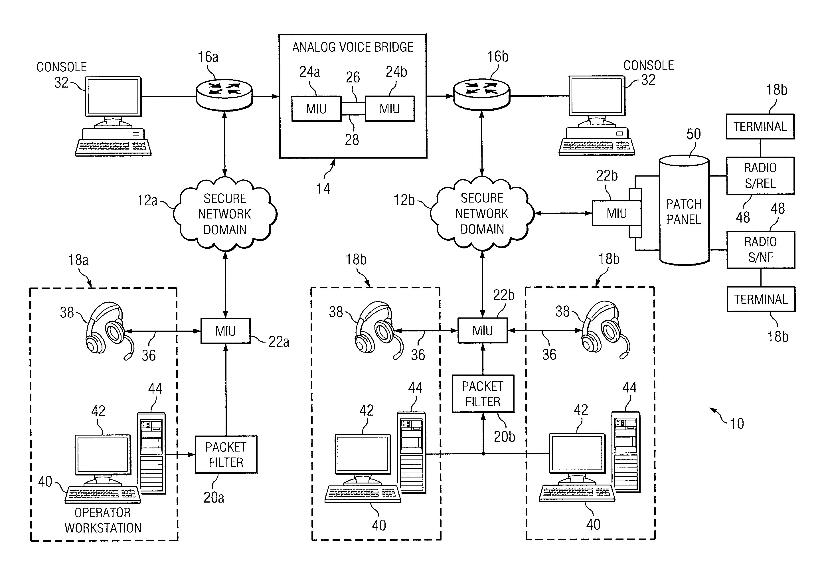
p-0010<figref idrefs="DRAWINGS">FIG. 1</figref> is a diagram showing one embodiment of a multi-level security network that may implement a user interface according to the teachings of the present disclosure;
p-0011<figref idrefs="DRAWINGS">FIG. 2</figref> is a screenshot showing one embodiment of a user interface of the computer system of <figref idrefs="DRAWINGS">FIG. 1</figref>;
p-0012<figref idrefs="DRAWINGS">FIG. 3</figref> is a diagram showing several elements of one embodiment of one network switch of <figref idrefs="DRAWINGS">FIG. 1</figref>;
p-0013<figref idrefs="DRAWINGS">FIG. 4</figref> is a diagram showing an example computing system that may be implemented with one or more codecs of <figref idrefs="DRAWINGS">FIG. 1</figref>;
p-0014<figref idrefs="DRAWINGS">FIG. 5</figref> is a schematic diagram showing one embodiment of multiple analog voice lines and signaling lines that may be configured to route analog voice signals and signaling, respectively between the computing systems of <figref idrefs="DRAWINGS">FIG. 1</figref>; and
p-0015<figref idrefs="DRAWINGS">FIG. 6</figref> is a flowchart showing one embodiment of a series of actions that may be performed by multi-level security network of <figref idrefs="DRAWINGS">FIG. 1</figref> to provide relatively secure voice communications across the security boundary formed by the analog voice bridge.
DETAILED DESCRIPTION OF EXAMPLE EMBODIMENTS
p-0016It should be understood at the outset that, although example implementations of embodiments are illustrated below, various embodiments may be implemented using any number of techniques, whether currently known or not. The present disclosure should in no way be limited to the example implementations, drawings, and techniques illustrated below. Additionally, the drawings are not necessarily drawn to scale.
p-0017Secure enterprise management of information processed on network computing systems may be accomplished by a multi-level security (MLS) architecture or a multiple independent levels of security (MILS) architecture. The multi-level security architecture usually incorporates a multi-tiered security scheme in which users have access to information managed by the enterprise based upon one or more authorization levels associated with each user. For example, enterprises, such as the government, utilize a multi-level security scheme that includes various security levels, such as unclassified, classified, secret, and top secret security levels, and may include one or more releasibility levels, such as a sensitive compartmented information (SCI), releasable (REL), and/or no foreign (NF) releasibility levels.
p-0018The United States Department of Defense (DoD) has issued a Director of Central Intelligence Directive 6/3 (DCID 6/3) entitled “Protecting Sensitive Compartmented Information Within Information Systems” for multi-level security architectures. The Director of Central Intelligence Directive 6/3 generally includes a set of guidelines for multi-level security networks that include several ascending levels of protection extending from a protection level <b>0</b> (PL<b>0</b>) to a protection level <b>5</b> (PL<b>5</b>). Specifically, the protection level <b>4</b> (PL<b>4</b>) protection level specifies that “The security support structure shall maintain separate execution domains (e.g., address spaces) for each executing process.”
p-0019Various protocols, such as a voice over Internet protocol (VoIP) have been established to provide voice communications over data networks. The voice over Internet protocol provides for conversion of analog voice signals to a digital data stream suitable for transmission over a network, and signaling techniques for establishing differing types of voice connections, such as direct calls, conference calls, and intercom sessions between two or more users. Implementation of voice communications on secure data networks using protocols such as voice over Internet protocol have been accomplished with varying degrees of success. One detrimental aspect of implementing voice communications on secure data networks is that spoken communication may not be inherently labeled in the same manner in which data is typically labeled. Thus, implementation of voice communications on secure data networks has been relegated to multiple independent levels of security architectures in which it is often limited to use with in the confines of its particular security level domain.
p-0020<figref idrefs="DRAWINGS">FIG. 1</figref> is a diagram showing one embodiment of a multi-level security network <b>10</b> that may implement a user interface according to the teachings of the present disclosure. Multi-level security network <b>10</b> includes at least two secure network domains <b>12</b><i>a </i>and <b>12</b><i>b </i>that may or may not be classified at different security levels, that may include a multi-level security scheme incorporating classification/releasibility levels. Secure network domain <b>12</b><i>a </i>is coupled to an analog voice bridge <b>14</b> through a network switch <b>16</b><i>a </i>and to one or more terminals <b>18</b><i>a </i>through a packet filter <b>20</b><i>a </i>and a voice interface gateway <b>22</b><i>a</i>, respectively. Respectively, secure network domain <b>12</b><i>b </i>is coupled to analog voice bridge <b>14</b> through a network switch <b>16</b><i>b </i>and to one or more terminals <b>18</b><i>b </i>through a packet filter <b>20</b><i>b </i>and a voice interface gateway <b>22</b><i>b</i>. Analog voice bridge <b>14</b> includes two codec <b>24</b><i>a </i>and <b>24</b><i>b </i>for converting a data packet stream from its respective secure network domain <b>12</b><i>a </i>and <b>12</b><i>b </i>to or from an analog voice stream suitable for transmission across an analog voice line <b>26</b>. Each network switch <b>16</b><i>a </i>and <b>16</b><i>b </i>is coupled to a console <b>32</b> for local configuration of its associated network switch <b>16</b><i>a </i>or <b>16</b><i>b. </i>
p-0021Terminals <b>18</b> may include a headset <b>38</b> and a computer system <b>40</b>. Computer system <b>40</b> has a user interface <b>42</b> for displaying information to a user and receiving input from the user. User interface <b>42</b> displays information about voice connections established in communication network <b>10</b>. User interface <b>42</b> may include an user output device such as a cathode ray tube (CRT), liquid crystal display (LCD), or a plasma display panel (PDP) that provides visual information. User interface <b>42</b> may also include a keyboard, mouse, console button, or other similar type user input device for providing user input to the communication network <b>10</b>. Computer system <b>40</b> may also execute a voice terminal program <b>44</b> for establishing and maintaining voice call sessions on multi-level security network <b>10</b>. In one embodiment, voice terminal program <b>44</b> is stored in the memory of computer system <b>40</b>. In other embodiments, voice terminal program <b>44</b> may be stored on another node of its respective secure network domain <b>12</b> in which the various functions provided by voice terminal program <b>44</b> are served to computer system <b>40</b> using a client/server model.
p-0022Computer system <b>40</b> executing voice terminal program <b>44</b> may be any suitable type, such as a network coupled computing system or a stand-alone computing system. An example stand-alone computer system <b>40</b> may be a personal computer, laptop computer, or mainframe computer capable of executing instructions of voice terminal program <b>44</b>. An example of a network computing system may include multiple computers coupled together via a network, such as a local area network (LAN), a metropolitan area network (MAN), or a wide area network (WAN).
p-0023In one embodiment, voice terminal program <b>44</b> comprises a JAVA applet that is stored in computer system <b>40</b> and executed in a web browser of computer system <b>40</b> in which voice communication through voice interface gateway <b>22</b> may be restricted to those terminals <b>18</b> using port <b>80</b> of the transfer control protocol (TCP) stack. Thus in some embodiments, the security of voice interface gateway <b>22</b> may be enhanced by restricting access to only those terminals <b>18</b> for which secure communication may be provided using commonly used components with well established security mechanisms, such as a hypertext transfer language secure (HTTPS) protocol. Voice interface gateways <b>22</b><i>a </i>and <b>22</b><i>b </i>may be coupled to terminals <b>18</b> in any suitable manner. In one embodiment, voice interface gateway <b>22</b><i>a </i>or <b>22</b><i>b </i>may send and receive analog voice signals through an analog voice line <b>36</b> coupled to headset <b>38</b> of terminal <b>18</b>, and may send and receive data packet information through packet filter <b>20</b><i>a </i>and <b>20</b><i>b </i>to computer system <b>40</b> of terminal <b>18</b>. The data packet information may be used for controlling voice connections of terminal <b>18</b> established through multi-level security network <b>10</b>.
p-0024Headset <b>38</b> may include any suitable type of electroacoustical transducer that converts analog voice signals to sound and vice-versa. For example, headset <b>38</b> may include a microphone for generating analog voice signals from sound and a speaker for generating sound from analog voice signals transmitted from remotely configure terminals <b>18</b>.
p-0025In another embodiment, voice interface gateway <b>22</b> may be coupled to one or more wireless networks <b>48</b>, such as a secret/releasable (S/REL) network or a secret/no foreign (S/NF) network. In some embodiments, a patch panel <b>50</b> may be provided to couple analog voice lines and data packet lines between voice interface gateway <b>22</b> and wireless networks <b>48</b> in an organized manner.
p-0026The multi-level security network <b>10</b> as shown may provide a defense-in-depth solution for voice communications across secure network domains <b>16</b><i>a </i>and <b>16</b><i>b </i>of an multi-level security architecture. Analog voice bridge <b>14</b> provides at least one layer of protection by allowing voice signals to pass while restricting passage of data packets between secure network domains <b>16</b><i>a </i>and <b>16</b><i>b</i>. Network switches <b>16</b><i>a </i>and <b>16</b><i>b </i>configured on either end of analog voice bridge <b>14</b> provide another level of protection by restricting data packets of their respective secure network domains <b>12</b><i>a </i>and <b>12</b><i>b </i>from accessing analog voice bridge <b>14</b> that are not intended for voice communication through analog voice bridge <b>14</b>. Packet filters <b>20</b><i>a </i>and <b>20</b><i>b </i>and voice interface gateways <b>22</b><i>a </i>and <b>22</b><i>b </i>provide yet another level of protection by restricting access of terminals <b>18</b> and users of those terminals <b>18</b> to only those having sufficient authorization to access analog voice bridge <b>14</b>. Additionally, the various elements of multi-level security network <b>10</b> may be configured with other features to provide other levels of protection for ensuring that the integrity of secure network domains <b>12</b><i>a </i>and <b>12</b><i>b </i>are not compromised while implementing voice communications on multi-level security network <b>10</b>.
p-0027Each codec <b>24</b><i>a </i>and <b>24</b><i>b </i>of analog voice bridge <b>14</b> converts data packets from its respective secure network domain <b>12</b> to or from an analog voice stream suitable for transmission across analog voice line <b>26</b>. An example codec <b>24</b><i>a </i>or <b>24</b><i>b </i>may include an analog to digital converter (ADC) for converting the analog voice stream to digital signal stream, a digital to analog converter (DAC) for converting the digital signal stream to the analog stream, and associated logic for encapsulating or decapsulating the analog voice stream to or from the digital signal stream in packets suitable for transmission over secure network domains <b>12</b><i>a </i>and <b>12</b><i>b</i>. Codec <b>24</b><i>a </i>and <b>24</b><i>b </i>may also be coupled to one another through one or more signaling lines <b>28</b> that control operation of analog signal lines <b>26</b>, such as providing call setup, call teardown, or other call negotiation procedures.
p-0028In one embodiment, codec <b>24</b><i>a </i>and <b>24</b><i>b </i>are configured on separate computing systems and coupled together only through analog voice lines <b>24</b> and signaling lines <b>28</b> such that physical separation according to PL<b>4</b> requirements may be maintained. Computing systems embodying codec <b>24</b><i>a </i>and <b>24</b><i>b </i>may be commercial-off-the-shelf computing systems capable of operating with a standard operating system, such as a Unix, Linux, Windows, or Macintosh operating system. Various elements of codec <b>24</b><i>a </i>and <b>24</b><i>b </i>will be described in greater detail below.
p-0029Each voice interface gateway <b>22</b><i>a </i>and <b>22</b><i>b </i>may include a codec for converting analog voice signals to and from a data packet stream suitable for transmission over secure network domains <b>12</b><i>a </i>and <b>12</b><i>b</i>, which may be, for example, an Ethernet network. In one embodiment, the codec configured in voice interface gateway <b>22</b> may be similar in design and construction to codec <b>24</b><i>a </i>and <b>24</b><i>b </i>of analog voice bridge <b>14</b>. In one embodiment, voice interface gateway <b>22</b> includes a commercially available computing system configured with multiple codec <b>24</b><i>a </i>and <b>24</b><i>b </i>and marketed under the tradename “Mercury Interface Unit”, which is available from Trilogy Communications Limited, and located in Andover, Hampshire, United Kingdom.
p-0030In one embodiment, analog voice line <b>26</b> comprises a pair of electrical conducting wires that convey analog voice signals whose voltage is proportional to its amplitude. In other embodiments, analog voice line <b>26</b> may include other types of signaling techniques that convey analog voice signals from codec <b>24</b><i>a </i>to and from codec <b>24</b><i>b</i>. For example, multiple analog voice signals may be multiplexed with one another on analog voice line using a time division multiplex access (TDMA) multiplexing technique. As another example, analog voice line <b>26</b> may convey a digital signal stream, such as a T<b>1</b> signal forming a digital representation of the analog voice signal.
p-0031Voice interface gateway <b>22</b> communicates information from terminals <b>18</b> to network switch <b>16</b> in any suitable manner. In one embodiment, voice interface gateway <b>22</b> communicates signaling information with terminals <b>18</b> using the transfer control protocol/Internet protocol (TCP/IP) and transfers digital voice signals through secure network domains <b>12</b><i>a </i>or <b>12</b><i>b </i>using a Real-Time Protocol (RTP) and Session Initiation Protocol (SIP).
p-0032Each packet filter <b>20</b><i>a </i>and <b>20</b><i>b </i>is coupled between computer system <b>40</b> of terminal <b>18</b> and voice interface gateway <b>22</b>. Packet filters <b>20</b><i>a </i>and <b>20</b><i>b </i>restrict access by terminal <b>18</b> to only those packets that are destined for voice communication. In many respects, packet filters <b>20</b><i>a </i>and <b>20</b><i>b </i>may perform functions that are generally similar to a commercial-off-the-shelf firewall. In one embodiment, each packet filter <b>20</b><i>a </i>and <b>20</b><i>b </i>may store an access control list that includes information associated with terminals <b>18</b> approved for voice communication through analog voice bridge <b>14</b>. Thus, packet filters <b>20</b><i>a </i>and <b>20</b><i>b </i>may provide another layer of protection for analog voice bridge <b>14</b> by implementing a positive inclusion mandatory access control (MAC) policy in which only those terminals <b>18</b> that are pre-registered for use via the access control list in packet filter <b>20</b><i>a </i>and <b>20</b><i>b </i>may be allowed to communicate through voice interface gateway <b>22</b>.
p-0033Packet filters <b>20</b><i>a </i>and <b>20</b><i>b </i>may be executed on any suitable computing system. For example, packet filter <b>20</b><i>a </i>and <b>20</b><i>b </i>may be executed on a stand-alone computing system that is separate and distinct from computer system <b>40</b> of terminal <b>18</b> or voice interface gateway <b>22</b>. As another example, packet filter <b>20</b><i>a </i>and <b>20</b><i>b </i>may be integrated with computer system <b>40</b> or voice interface gateway <b>22</b> in which data packets may be transferred between packet filter <b>20</b><i>a </i>and <b>20</b><i>b </i>and computer system <b>40</b> or voice interface gateway <b>22</b> internally.
p-0034<figref idrefs="DRAWINGS">FIG. 2</figref> is a screenshot showing one embodiment of a user interface <b>42</b> of the computer system <b>40</b> of <figref idrefs="DRAWINGS">FIG. 1</figref>. As shown, user interface <b>42</b> comprises a browser window executing voice terminal program <b>44</b> that performs the various functions of its associated terminal <b>18</b>, such as authorization of the user on terminal <b>18</b>, authorization of terminal <b>18</b><i>a </i>on multi-level security network <b>10</b>, call setup, call teardown, and/or other control sequences used to administer active voice sessions, such as push-to-talk signaling used with intercom voice sessions. In other embodiments, user interface <b>42</b> may be any suitable type of interface having one or more indicators for indicating the security level of active voice sessions to the user.
p-0035User interface <b>42</b> displays multiple cells <b>52</b> that are arranged in columns and rows. Each cell <b>52</b> displays indicators <b>54</b> representative of the security level of active voice sessions that have been established with its associated terminal <b>18</b><i>a</i>. For example, cell <b>52</b><i>a </i>includes an alpha-numeric text field indicator <b>54</b><i>b </i>describing the name and security level of the connected remote terminal <b>18</b>. Cell <b>52</b><i>a </i>is also filled with a color indicator, which is in this case dark gray, to indicate the “seceret” security level of the connected remote terminal <b>18</b> to the user. Cell <b>52</b><i>b </i>also includes an alpha-numeric text field indicator <b>54</b><i>b </i>describing the name and security level of the connected remote terminal <b>18</b>, Cell <b>52</b><i>a </i>is also filled with a color indicator, which is in this case light gray, to indicate the “top secret” security level of another connected remote terminal <b>18</b> to the user.
p-0036Indicators <b>54</b> may have any visual form that may be used to visually diffferentiate from among the differing security levels. For example, indicators <b>54</b> may display differing colors corresponding to differing security levels. As another example, indicators <b>54</b> may include differing patterns, such as cross-hatching, or other shading pattern to differentiate from among the differing security levels.
p-0037Terminals <b>18</b> may establish an intercom connection among one another such that more than two terminals <b>18</b> may communicate simultaneously. In some embodiments, indicators <b>54</b> may provide a visual indication of the security level associated with each connected terminal <b>18</b>. In one embodiment, indicators <b>54</b> may be dynamically modified as remote terminals are added or removed from the intercom connection. For example, a particular terminal <b>18</b> having a “secret” security level may join an ongoing intercom connection of other terminals <b>18</b> having a “top secret” security level. Once the particular terminal <b>18</b> joins, indicators <b>54</b> of the other terminals <b>18</b> having the “top secret” security level may be automatically lowered from “top secret” to “secret” to indicate to its users that the security level of the intercom connection has be lowered to the “secret” level. Conversely, when the particular terminal <b>18</b> leaves the intercom connection, indicators <b>54</b> of the other terminals <b>18</b> having the “top secret” security level may be automatically raised again to indicate a “top secret” security level to its users. Thus, indicators <b>54</b> of each terminal <b>18</b> of the intercom session may indicate the security level of the user having the lowest security level.
p-0038In one embodiment, each cell <b>52</b> displays a left ear indicator <b>54</b><i>b</i>, a speak indicator <b>54</b><i>c</i>, and a right ear indicator <b>54</b><i>d </i>that may be highlighted to indicate which remotely connected terminal <b>18</b> is coupled to the left earpiece, the microphone, and the right earpiece of the headset <b>38</b>. Thus, the user of terminal <b>18</b> may be provided with a visual indication as to which remotely coupled terminal <b>18</b> is speaking into his or her left ear, right ear, and to which remotely coupled terminal <b>18</b> is receiving voice signals generated from the microphone. As an example, the user may wish to listen to voice signals received from the remote terminal <b>18</b> represented by cell <b>52</b><i>a </i>and speak to the remote terminal <b>18</b> represented by cell <b>52</b><i>b </i>in which the user may actuate the left ear indicator <b>54</b><i>a </i>and right ear indicator <b>54</b><i>c </i>of cell <b>52</b><i>a</i>, and the speak indicator <b>54</b><i>b </i>of cell <b>52</b><i>b </i>may be actuated. Voice terminal program <b>44</b> may respond by highlighting the left ear indicator <b>54</b><i>a </i>and right ear indicator <b>54</b><i>c </i>of cell <b>52</b><i>a</i>, and the speak indicator <b>54</b><i>b </i>of cell <b>52</b><i>b</i>. This configuration may be modified at any time during the active voice sessions by actuating different left ear indicators <b>54</b><i>b</i>, speak indicators <b>54</b><i>c</i>, and right ear indicators <b>54</b><i>d </i>of other cells <b>52</b>.
p-0039User interface <b>42</b> may also display a security level summary window <b>56</b> that indicates the lowest security level to which terminal <b>18</b><i>a </i>or <b>18</b><i>b </i>is connected. In the particular embodiment shown, security level summary window <b>56</b> includes three cells corresponding to the left earpiece, microphone, and right earpiece of headset <b>38</b>.
p-0040Console <b>32</b> provides user configuration of its associated network switch <b>16</b><i>a </i>and <b>16</b><i>b </i>and may provide various features for ensuring proper operation of analog voice bridge <b>14</b>. In one embodiment, console <b>32</b> may monitor voice connections communicated through analog voice bridge <b>14</b> to ascertain any suspicious activity that may occur through illicit use. For example, console <b>32</b> may monitor signaling lines <b>28</b> for abnormal signaling sequences that may be attempted, such as repeated call setup attempts in an inordinately short period of time, or other call setup attempts to terminals <b>18</b> for which the calling terminal <b>14</b> may not be authorized to call. If suspicious activity is detected, console <b>32</b> may generate an alarm message that is sent to an appropriate system administrator for further investigation. In one embodiment, console <b>32</b> may also include a voice recording mechanism, such as a Stancil recorder or other similar device, that selectively records voice communications transmitted across analog voice bridge <b>18</b> for review at a later time. For example, it may be determined through various means that a particular user has been illicitly transmitting or receiving voice communications through analog voice bridge <b>14</b>. Thus, console <b>32</b> may be configured to record further voice communications of that user through analog voice bridge <b>14</b> and analyzed at a later time to determine the nature of the communications conducted through analog voice bridge <b>14</b>.
p-0041In one embodiment, console <b>32</b> may audit voice communications through analog voice bridge <b>14</b>. For example, console <b>32</b> may perform periodic audits of some or all terminals <b>14</b> that access other terminals <b>18</b> through analog voice bridge <b>14</b>. These audits may reveal certain patterns of voice call activity that may deviate from normal accepted usage. In this case, console <b>32</b> may generate an alarm message that is sent to an appropriate system administrator for further investigation.
p-0042<figref idrefs="DRAWINGS">FIG. 3</figref> is a diagram showing several elements of one embodiment of one network switch <b>16</b> of <figref idrefs="DRAWINGS">FIG. 1</figref>. Network switch <b>16</b> includes a console port <b>58</b>, two data ports <b>60</b><i>a </i>and <b>60</b><i>b</i>, a memory <b>62</b>, and a processor <b>64</b> coupled as shown. Memory <b>62</b> includes a monitoring tool <b>66</b>, an auditing tool <b>68</b>, and an accounting tool <b>70</b> that may be executed by processor <b>64</b>. Memory <b>62</b> also includes an access control list <b>72</b> that may be configured by console <b>32</b> to include those terminals <b>18</b> that may establish voice connections through analog voice bridge <b>14</b>. In the particular embodiment shown, network switch <b>20</b> switches data packets at the network layer (layer <b>3</b>) of the open system interconnect (OSI) model.
p-0043Network switch <b>16</b> restricts transmission of data packets between its associated secure network domain <b>12</b> and analog voice bridge <b>14</b> to only those data packets associated with digitized voice streams that are destined for transmission through analog voice bridge <b>14</b>. In one embodiment, each network switch <b>16</b> restricts all data packets to analog voice bridge <b>14</b> that have not originated from a voice interface gateway <b>22</b> configured on its associated secure network domain <b>12</b>. Thus in certain embodiments, security of the boundary formed by analog voice bridge <b>14</b> may be enhanced by restricting access from other nodes that may be coupled to its associated secure network domain <b>12</b>.
p-0044Network switch <b>16</b> provides various functions for maintaining security of its respective secure network domain <b>12</b>. In one embodiment for example, access control list <b>72</b> is configurable only by a console <b>32</b> coupled through console port <b>58</b>. By limiting configuration only through console <b>32</b>, configuration of access control list <b>72</b> from remotely coupled devices may be restricted. In this manner, illicit access across secure network domains <b>12</b> provided by reconfiguration of access control list <b>72</b> may be effectively mitigated or eliminated. Without this feature, for example, a particular node coupled to network switch <b>16</b> through its respective secure network domain <b>12</b> may be able to gain illicit access to the other secure network domain <b>12</b> by remotely configuring access control list <b>72</b> to allow unauthorized access to the other secure network domain <b>12</b> through analog voice bridge <b>14</b>.
p-0045Network switch <b>20</b> uses access control list <b>58</b> to regulate access of terminals <b>14</b> to analog voice bridge <b>18</b>. In one embodiment, network switch <b>20</b> implements a mandatory access control (MAC) such that only those terminals <b>14</b> previously registered in access control list <b>58</b> are allowed to place or receive intercom calls through analog voice bridge <b>18</b>.
p-0046<figref idrefs="DRAWINGS">FIG. 4</figref> is a diagram showing an example computing system <b>76</b> that may be implemented with one or more codecs <b>24</b> of <figref idrefs="DRAWINGS">FIG. 1</figref>. Computing system <b>76</b> includes a motherboard <b>78</b> coupled to a codec adapter card <b>80</b> and a signaling adapter card <b>82</b> through a suitable type of computer bus, such as a peripheral component interconnect (PCI) or an industry standard architecture (ISA) computer bus. Motherboard <b>78</b> has a processor <b>84</b> coupled to an Ethernet port <b>86</b> and a memory <b>88</b> that stores a codec/signaling controller <b>90</b> and a routing table <b>92</b>. Ethernet port <b>86</b> is coupled to a console <b>94</b> for configuration of routing table <b>92</b>. Although only one computing system <b>76</b> implemented with codec <b>24</b> is shown, it should be understood that codec <b>24</b> may be implemented in another computing system similar in design and construction to computing system <b>76</b> shown and described.
p-0047Processor <b>84</b> executes codec/signaling controller <b>90</b> to control codec adapter card <b>80</b> and signaling adapter card <b>82</b> for implementing the various features of analog voice bridge <b>14</b>. In one embodiment, computing system <b>76</b> is a commercial-off-the-shelf computing system capable of operating with a standard operating system, such as a Unix, Linux, Windows, or Macintosh operating system. In a particular embodiment, computing system <b>76</b> is a commercially available computing system configured with multiple codecs <b>24</b> and marketed under the tradename “Mercury Interface Unit”, which is available from Trilogy Communications Limited, and located in Andover, Hampshire, United Kingdom.
p-0048Routing table <b>92</b> stores routing information about terminals <b>18</b> that communicate through analog voice bridge <b>14</b>. Additionally, routing table <b>92</b> stores routing information about terminals <b>18</b> that communicate through analog voice bridge <b>14</b>. Two computing systems <b>76</b> embodying each codec <b>24</b><i>a </i>and <b>24</b><i>b </i>(<figref idrefs="DRAWINGS">FIG. 1</figref>) of analog voice bridge <b>14</b> may have their own routing table <b>92</b><i>a </i>and <b>92</b><i>b </i>such that registration of a communication link between terminals <b>18</b><i>a </i>and <b>18</b><i>b </i>configured on differing secure network domains <b>12</b><i>a </i>and <b>12</b><i>b </i>may be conducted independently of one another. Routing tables <b>92</b> may be configured according to a positive inclusion policy. That is, the only voice connections allowed through analog voice bridge <b>14</b> are those that have been previously registered on the routing tables <b>92</b> of both computing systems <b>76</b> embodying codecs <b>24</b> of analog voice bridge <b>14</b>.
p-0049In one embodiment, codec adapter card <b>80</b> may include one or more codecs <b>24</b> for providing multiple voice connections between secure network domains <b>24</b> simultaneously. Codec adapter card <b>80</b> also includes a dedicated Ethernet port <b>96</b> that receives and transmits digital voice packets from its respective secure network domain <b>12</b>. Providing an Ethernet port <b>96</b> separate from Ethernet port <b>86</b> may provide certain advantages including separation of voice traffic from configuration data packets used to configure the operation of codec/signaling controller <b>90</b>. Providing Ethernet port <b>96</b> separately from Ethernet port <b>86</b> may also provide another advantage in that its coupling to codecs <b>24</b> may be provided without connection through the computing system's computer bus connectors that may otherwise reduce throughput and/or signal quality of voice signals transferred between codecs <b>24</b> and Ethernet port <b>96</b>.
p-0050In one embodiment, routing table <b>92</b> is only locally configurable using console <b>94</b>. That is, modification of routing table <b>92</b> may be restricted from other access points of computing system <b>76</b>, such as Ethernet port <b>96</b> that would otherwise allow its modification through another node remotely configured on its associated secure network domain <b>12</b>. In this manner, illicit access across secure network domains <b>12</b> enabled by modification of routing table <b>92</b> may be effectively mitigated or eliminated. Without this feature, for example, a particular node coupled to computing system <b>76</b> through its respective secure network domain <b>12</b><i>b </i>(<figref idrefs="DRAWINGS">FIG. 1</figref>) may be able to gain illicit access to the other secure network domain <b>12</b><i>a </i>by remotely configuring routing table <b>92</b> to allow unauthorized access to the other secure network domain <b>12</b><i>b </i>through analog voice bridge <b>14</b>.
p-0051Signaling adapter card <b>82</b> includes one or more I/O ports <b>98</b> for transferring logic signals with signaling adapter card of its complementary computing system. Logic signals may include any suitable quantity and/or sequence of signals associated with voice connections across analog voice bridge <b>14</b>, such as calling sequences associated with a conference call session, or push-to-talk signaling used within conference call sessions. For example, codec/signaling controller <b>90</b> may receive a call request from terminal <b>18</b> configured on secure network domain <b>12</b><i>a </i>requesting a conference call session with terminal <b>18</b> configured on secure network domain <b>12</b><i>b</i>. In response to the call request, codec/signaling controller <b>90</b> controls I/O ports <b>98</b> to generate logic signals that are transmitted to I/O ports <b>98</b> of its complementary computing system for setting up a conference call with terminal <b>18</b>. Codec/signaling controller <b>90</b> of the complementary computing system <b>76</b> processes the received logic signals to initiate the conference call session with terminal <b>18</b>. In one embodiment, generation of logic signals through I/O ports <b>98</b> is restricted to control only by codec/signaling controller <b>90</b>. That is, the operation of I/O ports <b>98</b> may not be manipulated through instructions or messages received through Ethernet port <b>86</b>, Ethernet port <b>96</b>, or other communication interface provided on computing system <b>76</b>. In this manner, the security boundary provided between secure network domains <b>12</b><i>a </i>and <b>12</b><i>b </i>may not be breeched by performing illicit call signaling techniques from one computing system <b>76</b> to the other.
p-0052<figref idrefs="DRAWINGS">FIG. 5</figref> is a schematic diagram showing one embodiment of multiple analog voice lines <b>26</b> and signaling lines <b>28</b> that may be configured to route analog voice signals and signaling, respectively between computing systems <b>76</b>. Codec adapter card <b>80</b> and signaling adapter card <b>82</b> each include one or more connectors <b>100</b> and <b>102</b>, respectively, for physical interconnection with analog voice lines <b>26</b> and signaling lines <b>28</b>. In one embodiment, computing systems <b>76</b> embodying codecs <b>24</b> are configured in relatively close proximity to each other such that interconnection of analog voice lines <b>26</b> between computing systems <b>76</b> may be closely controlled. In one embodiment, analog voice lines <b>26</b> may be void of any active circuitry, such as busses, routers, or amplifiers that may increase their complexity and thus increase the possibility of an incorrect connection between computing systems <b>76</b>. In another embodiment, analog voice lines <b>26</b> and signaling lines <b>28</b> are color coded to match a color coding scheme of their associated connectors <b>100</b> and <b>102</b>. For the example shown in which codec adapter card includes eight connectors <b>100</b>, each connector <b>100</b> of codec adapter card <b>80</b> may be labeled with one of a black, brown, red, orange, yellow, green, blue, or violet colored label. Correspondingly, each of eight analog voice lines <b>26</b> may be labeled with similar individual colored labels. Using this color coding scheme, the possibility of inadvertent mismatch of analog voice lines <b>26</b> between computing system <b>76</b> may be reduced or eliminated.
p-0053Modifications, additions, or omissions may be made to analog voice bridge <b>14</b> without departing from the scope of the disclosure. The components of analog voice bridge <b>14</b> may be integrated or separated. For example, the components of codec adapter card <b>80</b> and/or signaling adapter card <b>82</b> may be implemented on a separate circuit card as shown or may be implemented with the other Moreover, the operations of analog voice bridge <b>14</b> may be performed by more, fewer, or other components. For example, computing systems <b>76</b> may each be configured with a hardware of software firewall to further restrict access to analog voice lines <b>26</b> and/or signaling lines <b>28</b> between the two secure network domains <b>12</b><i>a </i>and <b>12</b><i>b</i>. Additionally, operations of codec/signaling controller <b>90</b> may be performed using any suitable logic comprising software, hardware, and/or other logic.
p-0054<figref idrefs="DRAWINGS">FIG. 6</figref> is a flowchart showing one embodiment of a series of actions that may be performed by multi-level security network <b>10</b> to provide relatively secure voice communications across the security boundary formed by analog voice bridge <b>14</b>. In act <b>200</b>, the process is initiated.
p-0055In act <b>202</b>, terminals <b>18</b><i>a </i>and <b>18</b><i>b </i>configured on each secure network domain <b>12</b><i>a </i>and <b>12</b><i>b </i>are registered for use on multi-level security network <b>10</b>. Each terminal <b>18</b><i>a </i>and <b>18</b><i>b </i>may be registered for use in their respective secure network domains <b>12</b><i>a </i>and <b>12</b><i>b </i>by adding information associated with each terminal <b>18</b><i>a </i>and <b>18</b><i>b </i>in access control list <b>72</b> of its associated network switch <b>16</b><i>a </i>and <b>16</b><i>b </i>and the access control list configured in its associated packet filter <b>20</b><i>a </i>and <b>20</b><i>b</i>. In one embodiment, terminals <b>18</b><i>a </i>and <b>18</b><i>b </i>may also be registered for use by adding information associated with each terminal <b>18</b><i>a </i>and <b>18</b><i>b </i>in routing tables <b>92</b> associated with both codecs <b>24</b> configured in analog voice bridge <b>10</b>.
p-0056Registration of terminals <b>18</b><i>a </i>and <b>18</b><i>b </i>may include an authentication, authorization scheme for themselves as well as an authentication, authorization scheme for the user of terminals <b>18</b><i>a </i>and <b>18</b><i>b</i>. In one embodiment, authorization of the user of a terminal <b>18</b><i>a </i>or <b>18</b><i>b </i>may include validation of the user to use that particular terminal <b>18</b><i>a </i>or <b>18</b><i>b</i>. For example, a particular user having a security clearance level of secret may attempt to access a particular terminal <b>18</b><i>a </i>configured on a top secret secure network domain <b>12</b><i>a</i>. Thus, analog voice bridge <b>14</b> may reject the communication attempt due to lack of proper authorization of the user with that particular terminal <b>18</b><i>a. </i>
p-0057Registration of terminals <b>18</b><i>a </i>and <b>18</b><i>b </i>using routing tables <b>92</b> associated with each codec <b>24</b><i>a </i>and <b>24</b><i>b </i>provides a positive inclusion policy in which only voice sessions that have been previously registered may be allowed to communicate through analog voice bridge <b>14</b>. Routing table <b>92</b> may include information associated with terminals <b>18</b><i>a </i>configured on its secure network domain <b>12</b><i>a</i>, and terminals <b>18</b><i>b </i>coupled to the other secure network domain <b>12</b><i>b</i>. In one embodiment, registration of terminals <b>18</b><i>a </i>and <b>18</b><i>b </i>on each routing table <b>92</b> is only modifiable through a locally configured console <b>32</b>. That is, modification of routing tables <b>92</b> through a remote node that is remotely configured on secure network domain <b>12</b><i>a </i>or <b>12</b><i>b </i>may be restricted.
p-0058In one embodiment, routing tables <b>92</b> associated with each secure network domain <b>12</b><i>a </i>and <b>12</b><i>b </i>are manually modified by an information system security officer (ISSO) responsible for his or her secure network domain <b>12</b><i>a </i>or <b>12</b><i>b</i>. In this manner, registration of communication sessions through analog voice bridge <b>14</b> may be registered while maintaining physical separation of secure network domains <b>12</b><i>a </i>and <b>12</b><i>b </i>from one another. For example, it may be desired to provide a voice communication path from a terminal <b>18</b><i>a </i>configured on secure network domain <b>12</b><i>a </i>with another terminal <b>18</b><i>b </i>configured on the other secure network domain <b>12</b><i>b</i>. Following registration of terminals <b>18</b><i>a </i>and <b>18</b><i>b </i>with their associated secure network domains <b>12</b><i>a </i>and <b>12</b><i>b </i>as described with reference to act <b>202</b>, the information system security officers responsible for secure network domain <b>12</b><i>a </i>may modify their associated routing table <b>92</b> and communicate the desired voice communication path to the other information system security officer responsible for the other secure network domain <b>12</b><i>b</i>. The other information system security officer may then modify the routing table <b>92</b> associated with secure network domain <b>12</b><i>b </i>in analog voice bridge <b>14</b>.
p-0059In act <b>204</b>, packet filter <b>20</b> validates a connection request from terminal <b>18</b><i>a</i>. Packet request may validate the connection request in any suitable manner. In one embodiment, packet filter <b>20</b><i>a </i>validates the connection request according to a type of terminal <b>18</b><i>a </i>issuing the request. For example, packet filter <b>20</b><i>a </i>may forward only those connection requests that have originated from a particular browser application executed on computing system <b>76</b> of terminal <b>18</b><i>a</i>. In another embodiment, packet filter <b>20</b><i>a </i>validates the connection request according to information associated with that particular terminal <b>18</b><i>a </i>stored in its access control list. If the connection request is validated by packet filter <b>20</b><i>a</i>, processing continues at act <b>206</b>; otherwise the connection request is terminated and processing ends in act <b>216</b>.
p-0060In act <b>206</b>, network switch <b>16</b><i>a </i>receives the connection request from voice interface gateway <b>22</b><i>a </i>and validates the connection request. Network switch <b>16</b><i>a </i>validates the connection request in any suitable manner. In one embodiment, network switch <b>16</b><i>a </i>validates the connection request according to information stored in its access control list <b>72</b><i>a </i>associated with the terminal <b>18</b><i>a </i>issuing the connection request. If the connection request is validated by network switch <b>16</b><i>a</i>, processing continues at act <b>208</b>; otherwise the connection request is terminated and processing ends in act <b>216</b>.
p-0061In act <b>208</b>, analog voice bridge <b>14</b> receives the connection request from network switch <b>16</b><i>a </i>and validates the connection request according to routing table <b>92</b> associated with secure network domain <b>12</b><i>a</i>. If the connection request is validated in routing table <b>92</b>, computing system <b>76</b> transmits, using signaling lines <b>28</b>, the connection request to the other computing system <b>76</b> of analog voice bridge <b>14</b>. Computing system <b>76</b> may then verify that terminal <b>18</b><i>a </i>configured on its secure network domain <b>12</b><i>a </i>has been registered to communicate with other terminal <b>18</b><i>b </i>configured on secure network domain <b>12</b><i>b</i>. In one embodiment, computing systems <b>76</b> may use a proprietary signaling protocol to communicate through signaling lines <b>28</b>. In this manner, spoofing of connection requests transmitted through analog voice bridge <b>14</b> may be reduced or eliminated. In another embodiment, signaling lines <b>28</b> are restricted to convey only information necessary for establishing, maintaining, or tearing down voice connections through analog voice bridge <b>14</b>. Thus, signaling lines <b>28</b> may be restricted from transferring any information, such as data packets, from one computing system <b>76</b> to the other. If the connection request is validated by both computing systems <b>76</b>, an unused analog voice line <b>26</b> may be allocated for conveying analog voice signals between terminals <b>18</b><i>a </i>and <b>18</b><i>b </i>in which processing continues at act <b>210</b>. If the connection request is not validated, the connection request is terminated and processing ends in act <b>216</b>.
p-0062In act <b>210</b>, network switch <b>16</b><i>b </i>receives the connection request from analog voice bridge <b>14</b> and validates the connection request according to the receiving terminal <b>18</b><i>b</i>. In one embodiment, network switch <b>16</b><i>b </i>validates the connection request according to information stored in its access control list <b>72</b> associated with the terminal <b>18</b><i>b </i>coupled to its associated secure network domain <b>12</b><i>b</i>. If the connection request is validated by network switch <b>16</b><i>b</i>, processing continues at act <b>212</b>; otherwise the connection request is terminated and processing ends in act <b>216</b>.
p-0063In act <b>212</b>, packet filter <b>20</b><i>b </i>validates a connection request received from network switch <b>16</b><i>b</i>. Packet filter <b>20</b><i>b </i>validates the connection request in any suitable manner. In one embodiment, packet filter <b>20</b><i>b </i>validates the connection request according to a type of receiving terminal <b>18</b><i>b </i>receiving the connection request. In another embodiment, packet filter <b>20</b><i>b </i>validates the connection request according to information associated with that particular terminal <b>18</b><i>b </i>stored in its access control list. If the connection request is validated by packet filter <b>20</b><i>b</i>, processing continues at act <b>214</b>; otherwise the connection request is terminated and processing ends in act <b>216</b>.
p-0064In act <b>214</b>, user interface <b>42</b> prompts its user to accept or reject the incoming connection request from packet filter <b>20</b><i>b</i>. The connection request may alternatively be accepted or rejected by a user of terminal <b>18</b><i>b </i>in any suitable manner. For example, the user of terminal <b>18</b><i>b </i>may reject the connection request by ignoring the connection request, or may accept the connection request by actuating terminal <b>18</b><i>b </i>in a manner that causes the various elements of multi-level security network <b>10</b> to establish a voice connection between terminal <b>18</b><i>a </i>and terminal <b>18</b><i>b</i>. If the connection request is accepted by the user of terminal <b>18</b><i>b</i>, processing continues at act <b>216</b>; otherwise the connection request is terminated and processing ends in act <b>216</b>.
p-0065In act <b>216</b>, the connection is established and voice communications may be conducted from terminal <b>18</b><i>a </i>to terminal <b>18</b><i>b</i>. Once the connection is established, users of terminals <b>18</b><i>a </i>and terminal <b>18</b><i>b </i>may conduct a secure voice communication with one another through analog voice bridge <b>14</b>. When voice communication between terminals <b>18</b><i>a </i>and <b>18</b><i>b </i>are no longer needed or desired, the voice connection is removed and the process ends in act <b>216</b>.
p-0066Any suitable type of connection may be established through multi-level security network <b>10</b>. In one embodiment, terminal <b>18</b><i>a </i>may attempt to initiate an intercom connection in which ensuing voice messages with terminal <b>18</b><i>b </i>may be provided by a push-to-talk (PTT) voice message transmission scheme. Using the PTT voice message transmission scheme, voice messages originating at one terminal <b>18</b><i>a </i>or terminal <b>18</b><i>b </i>may be transmitted in half-duplex fashion to the other terminal <b>18</b><i>b </i>or <b>18</b><i>a </i>at the push of a button configured on the transmitting terminal <b>18</b><i>a </i>and <b>18</b><i>b</i>. In another embodiment, voice transmissions across multi-level security network <b>10</b> using a “hot mic” voice message transmission scheme may be restricted. The term “hot mic” voice message transmission scheme generally refers to transmission of voice messages over an intercom connection without manually operating a physical actuation device, such as a terminal mounted button. By restricting the use of “hot mic” voice message transmission schemes, therefore, the possibility of inadvertent voice transmission across security boundaries may be reduced or eliminated.
p-0067Modifications, additions, or omissions may be made to the method without departing from the scope of the disclosure. The method may include more, fewer, or other acts. For example, voice interface gateways <b>22</b><i>a </i>and <b>22</b><i>a </i>may include one or more voice compression/decompression algorithms for converting analog voice signals generated by terminals <b>18</b><i>a </i>and <b>18</b><i>b </i>into another form that may be transmitted over multi-level security network <b>10</b> at a reduced bandwidth. As another example, network switch <b>16</b><i>a </i>or <b>16</b><i>b </i>may execute any suitable auditing, monitoring, or accounting procedure for enhancing the security of voice communications transmitted between secure network domains <b>12</b><i>a </i>and <b>12</b><i>b. </i>
p-0068Although the present disclosure has been described with several embodiments, a myriad of changes, variations, alterations, transformations, and modifications may be suggested to one skilled in the art, and it is intended that the present disclosure encompass such changes, variations, alterations, transformation, and modifications as they fall within the scope of the appended claims.
Contents7
6 sheets
Sheet 1 Sheet 2 Sheet 3 Sheet 4 Sheet 5 Sheet 6
Every citation, both ways
| Document | Relation | Office | Cited during |
|---|---|---|---|
| US10257205B2 | Cited by | United States of America | Search report |
| US2018253565A1 | Cited by | United States of America | Search report |
| US10867065B2 | Cited by | United States of America | Search report |
| US11212257B2 | Cited by | United States of America | Search report |
| US10666643B2 | Cited by | United States of America | Applicant |
| US2018253565A1 | Cited by | United States of America | Search report |
| US10735196B2 | Cited by | United States of America | Applicant |
| US10834075B2 | Cited by | United States of America | Applicant |
| WO0137585A2 | Cites | World Intellectual Property Organization (WIPO) | Applicant |
| WO0137585A2 | Cites | World Intellectual Property Organization (WIPO) | Applicant |
| US2002097708A1 | Cites | United States of America | Applicant |
| US2002129236A1 | Cites | United States of America | Applicant |
| US2003018918A1 | Cites | United States of America | Applicant |
| US2003051130A1 | Cites | United States of America | Applicant |
| US2003128696A1 | Cites | United States of America | Applicant |
| US2003167394A1 | Cites | United States of America | Applicant |
| US2003224807A1 | Cites | United States of America | Applicant |
| US2004008423A1 | Cites | United States of America | Applicant |
| US2004034723A1 | Cites | United States of America | Applicant |
| US2004203799A1 | Cites | United States of America | Applicant |
| US2005257052A1 | Cites | United States of America | Search report |
| US2005268336A1 | Cites | United States of America | Search report |
| US2006020800A1 | Cites | United States of America | Applicant |
| US2006029050A1 | Cites | United States of America | Applicant |
| US2006230143A1 | Cites | United States of America | Applicant |
| US2007250921A1 | Cites | United States of America | Applicant |
| US2007297588A1 | Cites | United States of America | Applicant |
| US2008008312A1 | Cites | United States of America | Applicant |
| US2008275813A1 | Cites | United States of America | Search report |
| US2009260066A1 | Cites | United States of America | Search report |
| US2009271858A1 | Cites | United States of America | Applicant |
| WO2010135124A1 | Cites | World Intellectual Property Organization (WIPO) | Applicant |
| WO2010135124A1 | Cites | World Intellectual Property Organization (WIPO) | Applicant |
| WO2010135162A1 | Cites | World Intellectual Property Organization (WIPO) | Applicant |
| WO2010135162A1 | Cites | World Intellectual Property Organization (WIPO) | Applicant |
| WO2010135163A1 | Cites | World Intellectual Property Organization (WIPO) | Applicant |
| WO2010135163A1 | Cites | World Intellectual Property Organization (WIPO) | Applicant |
| US2010245107A1 | Cites | United States of America | Search report |
| US2010260173A1 | Cites | United States of America | Applicant |
| GB2264210A | Cites | United Kingdom | Applicant |
| US4981371A | Cites | United States of America | Applicant |
| US5577209A | Cites | United States of America | Applicant |
| US5974142A | Cites | United States of America | Applicant |
| US6122359A | Cites | United States of America | Applicant |
| US6243376B1 | Cites | United States of America | Applicant |
| US6392999B1 | Cites | United States of America | Applicant |
| US6411965B2 | Cites | United States of America | Applicant |
| US6445931B1 | Cites | United States of America | Applicant |
| US6728784B1 | Cites | United States of America | Applicant |
| US6760421B2 | Cites | United States of America | Applicant |
| US6771740B1 | Cites | United States of America | Applicant |
| US6775273B1 | Cites | United States of America | Applicant |
| US6813264B2 | Cites | United States of America | Applicant |
| US6829234B1 | Cites | United States of America | Applicant |
| US6857072B1 | Cites | United States of America | Applicant |
| US6930730B2 | Cites | United States of America | Applicant |
| US6967958B2 | Cites | United States of America | Applicant |
| US7099653B2 | Cites | United States of America | Applicant |
| US7127048B2 | Cites | United States of America | Applicant |
| US7133514B1 | Cites | United States of America | Applicant |
| US7139263B2 | Cites | United States of America | Applicant |
| US7149208B2 | Cites | United States of America | Applicant |
| US7221660B1 | Cites | United States of America | Applicant |
| US7343177B2 | Cites | United States of America | Applicant |
| US7415005B1 | Cites | United States of America | Applicant |
| US7508310B1 | Cites | United States of America | Search report |
| US7512967B2 | Cites | United States of America | Applicant |
| US7567555B1 | Cites | United States of America | Applicant |
| US7571317B1 | Cites | United States of America | Applicant |
| US7626951B2 | Cites | United States of America | Applicant |
| US7634533B2 | Cites | United States of America | Applicant |
| US7660575B2 | Cites | United States of America | Applicant |
| US7693131B2 | Cites | United States of America | Applicant |
| US7701974B2 | Cites | United States of America | Applicant |
| US7711828B2 | Cites | United States of America | Applicant |
| US7782826B2 | Cites | United States of America | Applicant |
| US7983199B1 | Cites | United States of America | Search report |
| CISCO Unified Comunications Manager: Security Guide, Release 7.0(1), CISCO Systems Inc., 2008, pp. 1-0 to 18-6. | Non-patent | – | Search report |
| Masiyowski et al., U.S. Appl. No. 12/686,886, filed Jan. 13, 2010, entitled "Analog Voice Bridge". | Non-patent | – | Applicant |
| Masiyowski et al., U.S. Appl. No. 12/686,814, filed Jan. 13, 2010, entitled "System and Method for Providing Voice Communications over a Multi-Level Secure Network". | Non-patent | – | Applicant |
| PCT Notification of Transmittal of the Intl. Search Report and the Written Opinion of the Intl. Searching Authority, or the Declaration mailed Oct. 1, 2010, re PCT/US2010/034823 filed May 14, 2010. | Non-patent | – | Applicant |
| PCT Notification of Transmittal of the Intl. Search Report and the Written Opinion of the Intl. Searching Authority, or the Declaration mailed Oct. 1, 2010, re PCT/US2010/034629 filed May 13, 2010. | Non-patent | – | Applicant |
| PCT Notification of Transmittal of the Intl. Search Report and the Written Opinion of the Intl. Searching Authority, or the Declaration mailed Oct. 5, 2010, re PCT/US2010/034824 filed May 14, 2010. | Non-patent | – | Applicant |
| Examination Report dated Dec. 8, 2011; for GB Pat. App. No. 1119955.1, Nov. 18, 2011; 6 pages. | Non-patent | – | Applicant |
| Response to Examination Report dated Dec. 8, 2011; for GB Pat. App. No. 1119955.1, filed Nov. 8, 2011; 7 pages. | Non-patent | – | Applicant |
| Examination Report under Section 18(3) of Great Britain; dated Jul. 9, 2012; for GB Pat. App. No. 111-9955.1; 2 pages. | Non-patent | – | Applicant |
| PCT/US2010/034823 International Report on Patentability dated Oct. 1, 2010, 8 pages. | Non-patent | – | Applicant |
| PCT/US2010/034824 Int'l Preliminary Report on Patentability dated Nov. 22, 2011, 8 pages. | Non-patent | – | Applicant |
| Office Action dated Jul. 9, 2012 for GB Appl. No. 1119955.1, 2 pages. | Non-patent | – | Applicant |
| Response to Office Action dated Jul. 9, 2012, filed Sep. 10, 2012 for GB Appl. No. 1119955.1, 3 pages. | Non-patent | – | Applicant |
| PCT Notification of Transmittal of the Intl. Search Report and the Written Opinion on the Intl. Searching Authority, or the Declaration mailed Oct. 5, 2010, re PCT/US2010/034824 filed May 14, 2010, 14 pages. | Non-patent | – | Applicant |
| U.S. Appl. No. 12/686,814, filed Jan. 13, 2010, file through Oct. 19, 2012, 611 pages, Part1. | Non-patent | – | Applicant |
| U.S. Appl. No. 12/686,814, filed Jan. 13, 2010, file through Oct. 19, 2012, 579 pages, Part2. | Non-patent | – | Applicant |
| U.S. Appl. No. 12/686,814, filed Jan. 13, 2010, file through Nov. 2, 2012, 64 pages. | Non-patent | – | Applicant |
| Letter dated Dec. 4, 2012 enclosing Official Notification of Grant of UK patent application No. GB1119955.1, issued Dec. 26, 2012, 3 pages. | Non-patent | – | Applicant |
| Office Action dated Nov. 20, 2012 for U.S. Appl. No. 12/086,814, filed Jan. 13, 2012, 18 pages. | Non-patent | – | Applicant |
| Response to Office Action dated Nov. 20, 2012 for U.S. Appl. No. 12/086,814, filed Feb. 19, 2013, 9 pages. | Non-patent | – | Applicant |
| Terminal Disclaimer filed Feb. 19, 2013, for U.S. Appl. No. 12/086,814, 1 page. | Non-patent | – | Applicant |
| Notice of Allowance in U.S. Appl. No. 12/666,814, filed Jan. 13, 2010, date mailed May 31, 2013, 12 pages. | Non-patent | – | Applicant |
| Office Action dated Aug. 30, 2013 in U.S. Appl. No. 12/688,836, filed Jan. 13, 2010, 26 pages. | Non-patent | – | Applicant |
12 members in 3 offices
Priority claims6
| Document | Office | Kind | Date |
|---|---|---|---|
| 21697909 | United States of America | P | |
| 21697909 | United States of America | P | |
| 68694610 | United States of America | A | |
| 61216979 | – | – | – |
| US20090216979P | – | – | – |
| US20100686946 | – | – | – |
Members12
| Document | Office | Kind | |
|---|---|---|---|
| US2010296444A1 | United States of America | A1 | |
| US2010296507A1 | United States of America | A1 | |
| US2010299724A1 | United States of America | A1 | |
| WO2010135124A1 | World Intellectual Property Organization (WIPO) | A1 | |
| WO2010135162A1 | World Intellectual Property Organization (WIPO) | A1 | |
| WO2010135163A1 | World Intellectual Property Organization (WIPO) | A1 | |
| GB201119955D0 | United Kingdom | D0 | |
| GB2481961A | United Kingdom | A | |
| GB2481961B | United Kingdom | B | |
| US8730871B2 | United States of America | B2 | |
| US8863270B2This record | United States of America | B2 | |
| US9160753B2 | United States of America | B2 |
103 transactions on the USPTO file
Allowed after 2 non-final rejections, 1 final rejection and 1 RCE.
- Non-final rejections
- 2
- Final rejections
- 1
- RCEs
- 1
- Appeals
- 0
Over time
Point at a mark for the transactionTransactions
| Event | Code | |
|---|---|---|
| Payment of Maintenance Fee, 12th Year, Large EntityM1553 | M1553 | |
| Payment of Maintenance Fee, 8th Year, Large EntityM1552 | M1552 | |
| Payment of Maintenance Fee, 4th Year, Large EntityM1551 | M1551 | |
| Recordation of Patent Grant MailedPGM/ | PGM/ | |
| Patent Issue Date Used in PTA CalculationAllowedPTAC | PTAC | |
| Email NotificationEML_NTR | EML_NTR | |
| Issue Notification MailedAllowedWPIR | WPIR | |
| Dispatch to FDCD1935 | D1935 | |
| Email NotificationEML_NTR | EML_NTR | |
| Printer Rush- No mailingTCPB | TCPB | |
| Mailing Corrected Notice of AllowabilityMCNOA | MCNOA | |
| Application Is Considered Ready for IssuePILS | PILS | |
| Reasons for AllowanceEX.R | EX.R | |
| Examiner's Amendment CommunicationEX.A | EX.A | |
| Corrected Notice of AllowabilityCNOA | CNOA | |
| Issue Fee Payment VerifiedN084 | N084 | |
| Response to Reasons for AllowanceREAS | REAS | |
| Issue Fee Payment ReceivedIFEE | IFEE | |
| Pubs Case Remand to TCPUBTC | PUBTC | |
| Printer Rush- No mailingTCPB | TCPB | |
| Printer Rush- No mailingTCPB | TCPB | |
| Pubs Case Remand to TCPUBTC | PUBTC | |
| Email NotificationEML_NTR | EML_NTR | |
| Mailing Corrected Notice of AllowabilityMCNOA | MCNOA | |
| Reasons for AllowanceEX.R | EX.R | |
| Examiner's Amendment CommunicationEX.A | EX.A | |
| Corrected Notice of AllowabilityCNOA | CNOA | |
| Interview Summary - Applicant Initiated - TelephonicEXAT | EXAT | |
| Interview Summary- Applicant InitiatedEXIA | EXIA | |
| Electronic ReviewELC_RVW | ELC_RVW | |
| Email NotificationEML_NTF | EML_NTF | |
| Mail Notice of AllowanceAllowedMN/=. | MN/=. | |
| Notice of Allowance Data Verification CompletedAllowedN/=. | N/=. | |
| Reasons for AllowanceEX.R | EX.R | |
| Examiner's Amendment CommunicationEX.A | EX.A | |
| Interview Summary - Examiner Initiated - TelephonicEXET | EXET | |
| Interview Summary - Examiner InitiatedEXIE | EXIE | |
| Information Disclosure Statement consideredIDSC | IDSC | |
| Information Disclosure Statement consideredIDSC | IDSC | |
| Date Forwarded to ExaminerFWDX | FWDX | |
| Response after Non-Final ActionA... | A... | |
| Mail Interview Summary - Applicant Initiated - TelephonicMEXAT | MEXAT | |
| Information Disclosure Statement (IDS) FiledM844 | M844 | |
| Information Disclosure Statement (IDS) FiledWIDS | WIDS | |
| Interview Summary- Applicant InitiatedEXIA | EXIA | |
| Interview Summary - Applicant Initiated - TelephonicEXAT | EXAT | |
| Electronic ReviewELC_RVW | ELC_RVW | |
| Email NotificationEML_NTF | EML_NTF | |
| Mail Non-Final RejectionNon-final rejectionMCTNF | MCTNF | |
| Information Disclosure Statement (IDS) FiledM844 | M844 | |
| Information Disclosure Statement (IDS) FiledWIDS | WIDS | |
| Non-Final RejectionNon-final rejectionCTNF | CTNF | |
| Date Forwarded to ExaminerFWDX | FWDX | |
| Disposal for a RCE / CPA / R129AbandonedABN9 | ABN9 | |
| Request for Continued Examination (RCE)RCEX | RCEX | |
| Workflow - Request for RCE - BeginBRCE | BRCE | |
| Interview Summary- Applicant InitiatedEXIA | EXIA | |
| Electronic ReviewELC_RVW | ELC_RVW | |
| Email NotificationEML_NTF | EML_NTF | |
| Mail Final Rejection (PTOL - 326)Final rejectionMCTFR | MCTFR | |
| Final RejectionFinal rejectionCTFR | CTFR | |
| Information Disclosure Statement consideredIDSC | IDSC | |
| Reference capture on IDSRCAP | RCAP | |
| Information Disclosure Statement (IDS) FiledM844 | M844 | |
| Information Disclosure Statement (IDS) FiledWIDS | WIDS | |
| Date Forwarded to ExaminerFWDX | FWDX | |
| Information Disclosure Statement consideredIDSC | IDSC | |
| Information Disclosure Statement (IDS) FiledM844 | M844 | |
| Information Disclosure Statement (IDS) FiledWIDS | WIDS | |
| Response after Non-Final ActionA... | A... | |
| Information Disclosure Statement consideredIDSC | IDSC | |
| Information Disclosure Statement (IDS) FiledM844 | M844 | |
| Reference capture on IDSRCAP | RCAP | |
| Information Disclosure Statement (IDS) FiledWIDS | WIDS | |
| Electronic ReviewELC_RVW | ELC_RVW | |
| Email NotificationEML_NTF | EML_NTF | |
| Mail Non-Final RejectionNon-final rejectionMCTNF | MCTNF | |
| Non-Final RejectionNon-final rejectionCTNF | CTNF | |
| Email NotificationEML_NTR | EML_NTR | |
| Change in Power of Attorney (May Include Associate POA)PA.. | PA.. | |
| Correspondence Address ChangeC.AD | C.AD | |
| Case Docketed to Examiner in GAUDOCK | DOCK | |
| Case Docketed to Examiner in GAUDOCK | DOCK | |
| Email NotificationEML_NTR | EML_NTR | |
| PG-Pub Issue NotificationPG-ISSUE | PG-ISSUE | |
| Information Disclosure Statement consideredIDSC | IDSC | |
| Information Disclosure Statement consideredIDSC | IDSC | |
| Reference capture on IDSRCAP | RCAP | |
| Information Disclosure Statement (IDS) FiledM844 | M844 | |
| Information Disclosure Statement (IDS) FiledWIDS | WIDS | |
| Information Disclosure Statement (IDS) FiledWIDS | WIDS | |
| Information Disclosure Statement consideredIDSC | IDSC | |
| Reference capture on IDSRCAP | RCAP | |
| Information Disclosure Statement (IDS) FiledM844 | M844 | |
| Information Disclosure Statement (IDS) FiledWIDS | WIDS | |
| Application Dispatched from OIPEOIPE | OIPE | |
| Email NotificationEML_NTR | EML_NTR | |
| Filing ReceiptFLRCPT.O | FLRCPT.O | |
| Sent to Classification ContractorPGPC | PGPC | |
| Cleared by L&R (LARS)L128 | L128 |
20 legal events, as the office reported them to INPADOC
Over the term
Point at a mark for the eventEvents
| Event | Code | |
|---|---|---|
| Maintenance fee paymentMAFP | MAFP | |
| AssignmentAS | AS | |
| AssignmentAS | AS | |
| AssignmentAS | AS | |
| Maintenance fee paymentMAFP | MAFP | |
| AssignmentAS | AS | |
| AssignmentAS | AS | |
| AssignmentAS | AS | |
| AssignmentAS | AS | |
| AssignmentAS | AS | |
| AssignmentAS | AS | |
| Maintenance fee paymentMAFP | MAFP | |
| AssignmentAS | AS | |
| AssignmentAS | AS | |
| AssignmentAS | AS | |
| AssignmentAS | AS | |
| AssignmentAS | AS | |
| Information on status: patent grantGrantedPATENTED CASESTCF | STCF | |
| Fee payment procedurePAYOR NUMBER ASSIGNED (ORIGINAL EVENT CODE: ASPN); ENTITY STATUS OF PATENT OWNER: LARGE ENTITYFEPP | FEPP | |
| AssignmentAS | AS |
Numbers
- Publication
- 08863270
- Publication, DOCDB
- 8863270
- Publication, EPODOC
- US8863270
- Application
- 12686946
- Application, DOCDB
- 68694610
- Application, EPODOC
- US20100686946
Titles
- English
- User interface for providing voice communications over a multi-level secure network
Patent term adjustment
- A delay
- +658 daysthe office missed an examination deadline
- B delay
- +364 dayspendency past three years
- Overlap
- −49 daysdelays counted once
- Applicant delay
- −118 days
- Net adjustment
- 855 days
Classification
- CPC, 6
- H04L63/105
- H04L63/00
- H04L63/30
- H04L65/1076
- H04L65/103
- H04L63/14
- IPC, 2
- G06F9 00
- H04L29 06
- USPC, 7
- 726015000
- 713151000
- 713153000
- 713166000
- 726004000
- 726014000
- 726030000