Female electrical contact, connector unit, and process for production
Summary by NHIP
Female electrical contact with tapered groove
The female electrical contact features a first connecting end with longitudinal slots that shifts between non-stressed and stressed states to reduce its diameter. An annular groove on the wall wall possesses a tapered cross-section in the non-stressed state and a straight cross-section in the stressed state, with a slope angle matching the required tightening angle.
Claim Score by NHIP
Abstract
A female electrical contact (100) has one connecting end (102) which is able to have two states, respectively a non-stressed state, and a stressed state, in which a connecting diameter is reduced, for receiving and maintaining the connection with a mating electrical contact. An annular gorge (107) in an undercut is provided on the wall (105) of the female electrical contact, such that in the non-stressed state, it has a tapered longitudinal cross-section, and in the stressed state, it has a straight longitudinal cross-section. A connector unit that includes at least one such contact, and a process for production are also described.
Term
Projected expiry 25 August 2031.
- Priority
- Filed
- Granted
- Today
- Projected expiry
12 claims: 1 independent, 11 dependent
- 1Broadest claimClaim Score 40, average(NHIP)A female electrical contact ( 100 ) with a general cylindrical circular shape that comprises two connecting ends ( 102 , 103 ), at least one first connecting end having at least two longitudinal slots, with said first connecting end being able to have two states, respectively a non-stressed state, in which said first connecting end has a straight, longitudinal cross-section, and a stressed state, in which said first connecting end has a tapered longitudinal cross-section, with an annular groove ( 107 ) being hollowed out from an outside surface ( 106 ) of the wall ( 105 ) of the female electrical contact, at the first connecting end, designed to receive a tightening element ( 108 ), characterized in that the annular groove has, when the first connecting end is in the non-stressed state, a tapered longitudinal cross-section such that the diameter of a front end of the annular groove is larger than the diameter of a rear end of said annular groove, and in that the annular groove has, when the first connecting end is in the stressed state, a straight cross-section;and wherein the annular groove has—in the non-stressed state of the first connecting end—a slope that has an angle (X 1 ) relative to a longitudinal axis (A′) of the female electrical contact that is essentially equal to a tightening angle (X 2 ) that has to be applied to the first connecting end to shift to the stressed state and to obtain a reduced connecting diameter (D″).
66 paragraphs in 4 sections, as filed
FIELD OF THE INVENTION
The invention relates to a female electrical contact that is designed to be equipped, around one of its connecting ends, with a tightening element that can keep said connecting end in a stressed state in order to reduce its connecting diameter. More particularly, the invention relates to a housing that is provided on the wall of the electrical contact and that is designed to receive and keep in position said tightening element. The invention also relates to a connector unit that comprises at least one such female electrical contact. The invention also relates to a process for production of such a female electrical contact.
BACKGROUND OF THE INVENTION
In the field of connection technology, it is sometimes necessary, in particular for uses in aeronautics and in the automotive industry, to use connecting elements that can maintain their electrical connections under extreme conditions. Actually, the electrical connections can be subjected to strong vibrations and/or elevated temperature differentials, tending to deteriorate the electrical connection between two mating contacts.
In general, one connecting end of a female electrical contact or socket is specifically sized to receive a mating male contact or pin. The materials that are used, namely copper alloys such as brass or bronze, are selected for their ability to maintain their mechanical characteristics at temperature so as to prevent untimely expansions from breaking the electrical connection.
Most of these materials most often have a loss of their elasticity when they are subjected to temperatures of greater than 200° C., such that when the pin is introduced into the socket, there is not necessarily a sufficient tightening of said socket around said pin when the temperature approaches or exceeds 200° C.
Also, it is known to use a female electrical contact, or socket, such as a female power contact, equipped with an annular tightening element, so as to tighten the wall of the socket around the pin and thus promote maintaining the electrical connection even in the case of strong vibrations and/or high temperatures.
The characteristics of the materials used for this annular tightening element are such that their elasticity is maintained for temperatures of greater than 200° C.
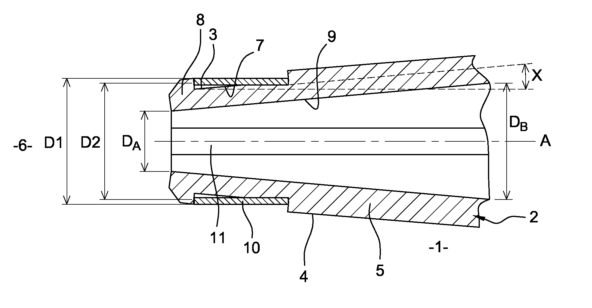
<figref idrefs="DRAWINGS">FIG. 1</figref> shows a partial longitudinal cutaway of such a female electrical contact <b>1</b> at the end of the tightened connection <b>6</b>.
DETAILED DESCRIPTION OF THE INVENTION
More specifically, the socket <b>1</b> comprises a socket body <b>2</b> that has a general cylindrical circular shape. Longitudinal slots are made in the socket body, extending along the longitudinal axis A, from the opening <b>11</b> of the connecting end <b>6</b> and over a partial length of the socket body <b>2</b>. In general, at least two longitudinal slots are made on the connecting end <b>6</b>.
Only the connecting end <b>6</b> under consideration has been tightened in such a way as to have a connecting diameter DA, corresponding to the inside diameter at the opening <b>11</b> of said end <b>6</b>, reduced relative to the inside diameter DB of the rest of the socket body <b>2</b>. The diameter DA is bordered by the inside surface <b>9</b> of the wall <b>5</b> of the female contact <b>1</b>.
The connecting diameters DA and DB are determined based on the diameter D of the pin that is to be introduced in such a way as to have DA<D<DB. Actually, the inside surface <b>9</b> of the wall <b>5</b> at the connecting end <b>6</b> is to be attached with pressure to the outside wall of the pin, and this pressure is to be maintained so as to ensure the electrical connection between these two elements. Thus, the deformation is such that the connecting end <b>6</b> has a tapered longitudinal cross-section, with the inside diameter of the cavity increasing from the connecting diameter DA at the opening <b>11</b> toward DB at the bottom of the cavity.
An annular groove <b>3</b> is hollowed out from the outside surface <b>4</b> of the wall <b>5</b> of the socket body <b>2</b> to receive a tightening ring. The groove <b>3</b> extends over the entire outside perimeter of the connecting end <b>6</b> of the socket <b>1</b>. Lips of stop <b>8</b> are provided upstream from the groove <b>3</b>. Thus, the groove <b>3</b> is bordered upstream by the lips of stop <b>8</b> and downstream by the wall <b>5</b> of the non-machined socket body <b>2</b>. Upstream and downstream are defined relative to the direction of the connection at the end being considered.
A bottom <b>7</b> of the groove <b>3</b> is inclined by an angle X relative to a longitudinal axis A of the socket body <b>2</b>, corresponding to the tightening angle applied to the connecting end <b>6</b> to obtain the desired connecting diameter DA.
The tightening ring <b>10</b> is housed in the groove <b>3</b> in such a way as to surround the connecting end <b>6</b>. The tightening ring <b>10</b> conventionally has a tubular shape and has a straight cross-section relative to the axis A, such that it does not rest over its entire length on the bottom <b>7</b> of the groove <b>3</b>.
To house the tightening ring <b>10</b> in the groove <b>3</b>, said tightening ring <b>10</b> is slid along the wall <b>5</b> of the socket body <b>2</b>, from the lips of stop <b>8</b> that border the opening <b>11</b>.
The tightening ring <b>10</b> is therefore to pass above lips of stop <b>8</b> before ending in the groove <b>3</b>. However, an outside diameter D<b>1</b> of the connecting end <b>6</b> at the lips of stop <b>8</b> is larger than an inside diameter D<b>2</b> of the tightening ring <b>10</b>, since said lips of the stop are to prevent the untimely removal of said tightening ring <b>10</b>. Inside diameter is defined as the diameter that is measured from the inside surface of the element being considered, while the outside diameter corresponds to the diameter that is measured from the outside surface of the element being considered.
The tightening ring <b>10</b> is generally made of material that can withstand high temperatures, while preserving its elastic properties thus providing a spring action.
It often happens that such materials have elastic characteristics over reduced operating ranges and that strong deformations linked to assembly operations make them shift from an elastic range to a plastic range, with the consequent loss of the spring action.
Also, it is common that the stresses imposed on the tightening ring <b>10</b> during the shifting of the lips of stop <b>8</b>, above the diameter D<b>1</b> in particular, make it shift to the plastic state, taking into account the strong deformation imposed. The tightening ring <b>10</b> is then no longer able to correctly perform its function of tightening and maintaining the connecting diameter DA.
In the invention, it is sought to provide a female electrical contact that can be used even under conditions of strong vibrations and high temperatures, not exhibiting all or part of the drawbacks of the female electrical contacts of the prior art.
For this purpose, the invention proposes machining—at the end of the connection of interest—a groove in an undercut, with the angle of the undercut corresponding essentially to the tightening angle to obtain the desired reduced diameter at said connecting end. Undercut is defined as the groove being provided in such a way that its bottom is inclined longitudinally. Thus, the bottom of the groove in an undercut has, before the tightening of the first connecting end, a slope relative to the longitudinal axis of the female electrical contact such that the diameter of the front end of the groove in an undercut is larger than the diameter of the rear end of said groove in an undercut. In a general manner, front and rear, or upstream and downstream, are defined relative to the direction of the connection at the connecting end being considered. The diameter of the groove is considered at the bottom of said groove. Once the tightening is done, the groove has a straight cross-section, parallel to the longitudinal axis of the contact. An annular tightening element, such as a ring, also with a straight cross-section, can then be used in an optimum manner, since its entire surface rests in an equal manner on the bottom of the groove. The diameter of the connecting end at the lips of the stop is reduced relative to the system of the prior art described above, reducing the displacement in order for the tightening element to pass through this stop.
The invention therefore has as its object a female electrical contact with a general cylindrical circular shape that comprises two connecting ends, at least one first connecting end having at least two longitudinal slots, with said first connecting end being able to have two states, respectively a non-stressed state, in which said first connecting end has a straight longitudinal cross-section, and a stressed state, in which said first connecting end has a tapered longitudinal cross-section, with an annular groove being hollowed out from an outside surface of the wall of the female electrical contact, at the first connecting end, designed to receive a tightening element,
characterized in that the annular groove has, when the first connecting end is in the non-stressed state, a tapered longitudinal cross-section such that the diameter of a front end of the annular groove is larger than the diameter of a rear end of said annular groove, and in that the annular groove has, when the first connecting end is in the stressed state, a straight cross-section.
The non-stressed state is the state in which the contact is found before being tightened to have a reduced connecting diameter at one of its two connecting ends.
When one of the two connecting ends is deformed/tightened to reduce its opening diameter, the rest of the body of the contact and the second connecting end are not deformed, and it continues to have a cylindrical circular shape. The deformation/stress is only local.
Connecting diameter is defined as the inside diameter of the contact at the connecting end being considered.
Reduced diameter means that the diameter that is being considered is less than the diameter of the rest of the cylindrical circular contact.
The groove extends over a certain length of the connecting end, enough to receive a tightening element that is also annular, able to maintain a tightening pressure around said connecting end and to make it possible to hold the reduced connecting diameter under all circumstances.
Length is defined as the dimension that extends parallel to the longitudinal axis of the element being considered.
The stressed state is obtained mechanically by tightening the opening diameter at the connecting end. The tightening of the connecting end tends to bring the bottom of the groove parallel to the longitudinal axis of the contact. The slope of the groove decreases to almost zero, it being understood that the fact of manufacturing stresses, a slight slope relative to the longitudinal axis in one direction or in the other, may be acceptable.
Longitudinal cross-section is defined as a cross-section in a longitudinal plane of the female electrical contact.
Advantageously, the annular groove has—in the non-stressed state of the first connecting end—a slope that has an angle relative to a longitudinal axis of the female electrical contact that is essentially equal to a tightening angle that has to be applied to the first connecting end to shift to the stressed state and to obtain a reduced connecting diameter.
According to the invention, the female electrical contact can comprise a tightening element that is placed in the annular groove and is able to keep the first connecting end in the stressed state, whereby said tightening element has a straight longitudinal cross-section.
The annular tightening element is designed to be mounted on the connecting end once it is in the constrained/tightened state. Thus, during assembly, because of the initial shape in an undercut of the groove, excessive stresses are not exerted on said ring.
The tightening element is to be able to keep the connecting end in the stressed state even when significant forces are applied, tending to make said connecting end return to a non-stressed state.
Preferably, the tightening element has mechanical properties such as elasticity, which make it particularly suitable for operating at temperatures of more than 200° C.
In one embodiment, the front end of the annular groove is bordered by lips of a stop. These lips of a stop can be obtained by, for example, machining the groove downstream from the opening of the connecting end in such a way that said groove does not protrude at said opening. Thus, the non-hollowed-out wall of the contact, upstream from the groove, forms the lips of the stop. Otherwise, these lips of the stop can be connected to the connecting end and attached in particular by welding.
The groove is thus bordered by two vertical walls, and the outside diameter of the contact at said lips of the stop, as well as downstream from the groove, is larger than the outside diameter of the contact at the bottom of the groove. Likewise, the outside diameter at said lips of the stop, as well as downstream from the groove, is larger than the inside diameter of the tightening element, which ensures—once it is installed—that the tightening element will remain in the proper position in the groove.
The tightening element can be, for example, a slit cylindrical circular ring.
The slot thus makes it possible to facilitate the passage of the lips of the stop without exerting excessive stresses on the ring.
The tightening element can otherwise be a cylindrical circular helical spring, with the manufacturing cost of such a spring often being less.
The invention also relates to a connector unit comprising an insert that is equipped with at least one through cavity, designed to receive two mating electrical contacts, whereby said connector unit comprises at least one female electrical contact, or socket, according to the invention, and at least one mating male electrical contact, or pin, able to be inserted into at least one through cavity of the insert.
The male and female contacts are each introduced into a cavity of the insert that is being considered, by an opposite end, in such a way that a connecting zone between the two mating electrical contacts is located inside said cavity.
The invention also relates to a process for the production of a female contact element according to the invention, comprising the following stages: <ul><li id="ul0001-0001" num="0000"><ul><li id="ul0002-0001" num="0044">A female electrical contact, of general circular cylindrical shape, equipped at each of its ends with a connecting end, is produced to be connected to a mating electrical contact or a cable;</li><li id="ul0002-0002" num="0045">At least one longitudinal slot is machined at a first connecting end;</li><li id="ul0002-0003" num="0046">An annular groove is machined from the outside surface of the wall of the female electrical contact, at the first connecting end, in such a way that a bottom of the groove extends along an axis that is inclined relative to a longitudinal axis of the female electrical contact, such that the diameter of a front end of the annular groove is larger than the diameter of a rear end of said annular groove;</li><li id="ul0002-0004" num="0047">The first connecting end is tightened in such a way as to reduce the connecting diameter at said first connecting end, until the bottom of the groove extends along an axis that is parallel to the longitudinal axis of the female electrical contact;</li><li id="ul0002-0005" num="0048">A tightening element is slid along the outside wall of the female contact until it is housed entirely in the annular groove.</li></ul></li></ul>
According to an embodiment of the process of the invention, it is possible to provide the following additional stage: <ul><li id="ul0003-0001" num="0000"><ul><li id="ul0004-0001" num="0050">Simultaneously with the annular groove, lips of the stop are provided, upstream from said annular groove, such that the outside diameter of the female electrical contact at said lips of the stop is larger than the outside diameter of the female electrical contact at the bottom of the groove and larger than the inside diameter of the tightening element.</li></ul></li></ul>
BRIEF DESCRIPTION OF THE DRAWING
The invention will be better understood from reading the following description and from the examination of the accompanying figures. The latter are presented by way of indication and are in no way limiting of the invention. The figures show:
<figref idrefs="DRAWINGS">FIG. 1</figref>: A longitudinal cutaway view of a connecting end of a female electrical contact of the prior art already described,
<figref idrefs="DRAWINGS">FIG. 2</figref>: A general view of a female electrical contact according to the invention;
<figref idrefs="DRAWINGS">FIGS. 3A to 3C</figref>: Longitudinal cutaway views of a connecting end of a female electrical contact according to the invention;
<figref idrefs="DRAWINGS">FIG. 4</figref>: A longitudinal cutaway view of a female electrical contact according to the invention, connected to a mating male electrical contact.
For the purpose of simplifying and clarifying the figures, the same references in different figures designate the same elements.
<figref idrefs="DRAWINGS">FIG. 2</figref> shows an embodiment of a female electrical contact <b>100</b> according to the invention.
The female electrical contact <b>100</b>, or socket, comprises a socket body <b>101</b>, with a general hollow cylindrical shape with a circular cross-section, or a cylindrical circular cross-section. The two ends <b>102</b>, <b>103</b> of the cylinder are open and provide connecting ends, each designed to receive a mating male electrical contact, or pin, or a cable. The connecting end <b>102</b> that is designed to receive a pin (at the right in <figref idrefs="DRAWINGS">FIG. 2</figref>) is slit longitudinally. The two slots <b>104</b> make it possible to facilitate the tightening of said end <b>102</b>, without an overlapping of material.
A wall <b>105</b> of the socket body <b>101</b> is hollowed out from an outside surface <b>106</b> in such a way as to provide an annular groove <b>107</b> in an undercut. A slit annular tightening element <b>108</b> surrounds an outside perimeter of the socket body <b>101</b>. The tightening ring <b>108</b> is more specifically housed in the annular groove <b>107</b>, in which it is held in position, in particular using lips of stop <b>109</b>.
<figref idrefs="DRAWINGS">FIGS. 3A</figref>, <b>3</b>B and <b>3</b>C show more precisely the shape of the undercut of the annular groove <b>107</b> (<figref idrefs="DRAWINGS">FIG. 3A</figref>) in the non-stressed state (<figref idrefs="DRAWINGS">FIG. 3A</figref>), and the shape of the straight cross-section of said annular groove <b>107</b> in the stressed state (<figref idrefs="DRAWINGS">FIGS. 3B and 3C</figref>).
In a first step, the annular groove <b>107</b> is hollowed out or machined on the socket body <b>101</b>, on a slant from the outside surface <b>106</b> of the wall <b>105</b>, which it extends essentially parallel to a longitudinal axis A′ of the socket body <b>101</b>. Thus, an upstream depth p of the annular groove <b>107</b> is less than a downstream depth p′ of said groove <b>107</b>. Depth is defined as the dimension that extends radially relative to the axis A′. In other words, the outside diameter at the upstream level of the annular groove <b>107</b> is larger than the outside diameter at the downstream level of the annular groove <b>107</b>. The bottom <b>110</b> of the groove <b>107</b>, flat, extends along an axis I that is inclined by an angle X<b>1</b> relative to the longitudinal axis A′. An inside diameter D′ of the opening <b>111</b> of the connecting end <b>102</b> corresponds to the general inside diameter of the socket body <b>101</b>.
The angle X<b>1</b> is advantageously predetermined based on the tightening angle X<b>2</b> that will next be applied at the connecting end <b>102</b>, in such a way that once the tightening is carried out, the bottom <b>110</b> of the groove <b>107</b> extends essentially parallel to the axis A′ of the contact <b>100</b>. The tightening angle X<b>2</b> should correspond to the angle to be applied to obtain a reduced connecting diameter D″ (<figref idrefs="DRAWINGS">FIG. 3B</figref>) that can allow the electrical connection with a mating male contact. The reduced connecting diameter D″ corresponds to the inside diameter of the connecting end at the opening <b>111</b>. In a general manner, according to the invention, the angle X<b>1</b> is essentially equal to the tightening angle X<b>2</b>.
The groove <b>107</b> is produced at a distance from the opening <b>111</b> of the connecting end <b>102</b> in such a way as to provide lips of stop <b>109</b> upstream from the groove <b>107</b>.
Next, the connecting end <b>102</b> is tightened in such a way as to reduce the diameter of the opening <b>111</b> until the reduced diameter D″ corresponding to the desired diameter is obtained based on the dimensions of the pin that is to be inserted. The wall <b>105</b> of the socket body <b>101</b> is thus locally inclined by the angle X<b>2</b>, while the bottom <b>110</b> of the groove <b>107</b> is itself parallel to the axis A′. Also, the outside diameter at the annular groove <b>107</b> is constant over its entire length. Length is defined as the dimension that extends essentially parallel to the longitudinal axis A′.
The longitudinal cross-section of the connecting end <b>102</b> is then tapered. The inside diameter like the outside diameter of the connecting end are increasing from the opening <b>111</b> that has the reduced inside diameter D″ to a separation partition <b>112</b> (<figref idrefs="DRAWINGS">FIG. 4</figref>) that separates the two connecting ends <b>102</b>, <b>103</b>. The rest of the socket body <b>101</b>, as is visible in <figref idrefs="DRAWINGS">FIG. 2</figref>, is not deformed by this tightening stage of the connecting end <b>102</b>, whose inside diameter remains equal to the initial diameter D′.
Once the reduced diameter D″ is obtained, the tightening ring <b>108</b> is brought opposite the opening <b>111</b> of the connecting end <b>102</b>. The passage of said tightening ring <b>108</b> is forced at the opening <b>111</b> so as to make it overlap the lips of stop <b>109</b>. Actually, the connecting end <b>102</b> has—at the lips of stop <b>109</b>—an outside diameter D<b>1</b>′ that is larger than the inside diameter D<b>2</b>′ of the tightening ring <b>108</b>. However, according to the invention, with the groove <b>107</b> that at this time has a straight cross-section, the outside diameter D<b>1</b>′ at the lips of the stop of the socket <b>100</b> is strictly smaller than the outside diameter D<b>1</b> at the lips of the stop of a socket <b>1</b> (<figref idrefs="DRAWINGS">FIG. 1</figref>) of the prior art of equivalent dimensions.
Thus, in a general manner, the difference in diameter between D<b>1</b>′ and D<b>2</b>′ is between 0.2 mm and 0.8 mm, whereas for a socket <b>1</b> of the prior art, the difference in diameter between D<b>1</b> and D<b>2</b> (<figref idrefs="DRAWINGS">FIG. 1</figref>) is, by contrast, between 1 mm and 1.2 mm. This difference in the diameter fluctuations makes it possible to prevent the tightening ring <b>108</b> from being subjected to stresses as it transitions to a detrimental plastic state. It is therefore possible to use—for the tightening ring <b>108</b> or in a general manner for the tightening element—materials that are less elastic, such as simple brasses ensuring a better tightening behavior of the connecting end <b>102</b> and thus of the connection between the socket and the associated pin.
The tightening ring <b>108</b> is next slid along the outside surface <b>106</b> of the wall <b>105</b> of the socket body <b>101</b> until it is entirely contained in the groove <b>107</b> (<figref idrefs="DRAWINGS">FIG. 3C</figref>).
The upstream depth p and downstream depth p′ of the groove <b>107</b> are enough to prevent the involuntary withdrawal of the tightening ring <b>108</b>. With the tightening ring <b>108</b> having a straight cross-section, it extends over its entire length parallel to the bottom <b>110</b> of the groove <b>107</b> in such a way that the stresses exerted by said tightening ring <b>108</b> on the connecting end <b>102</b> are essentially constant.
<figref idrefs="DRAWINGS">FIG. 4</figref> shows a female electrical contact <b>100</b> according to the invention, connected at one connecting end <b>102</b> with a reduced connecting diameter to a mating male electrical contact <b>200</b>.
The largest outside diameter D<b>3</b> of the male contact <b>200</b>, at the connecting end <b>201</b> inserted into the reduced connecting end <b>102</b>, is 5.41 mm. The outside diameter D<b>1</b>′ at the lips of stop <b>109</b> is 6.8 mm, while the inside diameter D<b>2</b>′ of the tightening element <b>108</b> (here a cylindrical circular helical spring) is 6.5 mm. The reduced connecting diameter D″, corresponding to the smallest diameter of the connecting end <b>102</b>, located at the opening <b>111</b> of said connecting end <b>102</b>, is 5.4 mm.
Thus, the male contact <b>200</b> is introduced in force in the connecting end <b>102</b> of the female contact <b>100</b>, and the tightening element <b>108</b> ensures that the reduced connecting diameter D″ is maintained.
Contents4
4 sheets
Sheet 1 Sheet 2 Sheet 3 Sheet 4
Every citation, both waysCites: the store holds 32 of 33
| Document | Relation | Office | Cited during |
|---|---|---|---|
| US10535948B2 | Cited by | United States of America | Search report |
| US2015311615A1 | Cited by | United States of America | Pre-grant |
| US8834212B2 | Cited by | United States of America | Search report |
| US2017244196A1 | Cited by | United States of America | Pre-grant |
| US2022173600A1 | Cited by | United States of America | Search report |
| US9431741B2 | Cited by | United States of America | Search report |
| US10348037B2 | Cited by | United States of America | Search report |
| US11522375B2 | Cited by | United States of America | Search report |
| US8733689B2 | Cited by | United States of America | Search report |
| US2012295492A1 | Cited by | United States of America | Pre-grant |
| US2017244196A1 | Cited by | United States of America | Search report |
| US2011111605A1 | Cited by | United States of America | Pre-grant |
| WO2019082816A1 | Cited by | World Intellectual Property Organization (WIPO) | International search |
| US1677068A | Cites | United States of America | Search report |
| US2007190868A1 | Cites | United States of America | Search report |
| JP2009054374A | Cites | Japan | Applicant |
| US2009278788A1 | Cites | United States of America | Search report |
| CN201038406Y | Cites | China | Applicant |
| US2346831A | Cites | United States of America | Search report |
| US3229243A | Cites | United States of America | Search report |
| US3586802A | Cites | United States of America | Search report |
| US3924922A | Cites | United States of America | Search report |
| US4035045A | Cites | United States of America | Search report |
| US4168878A | Cites | United States of America | Search report |
| US4192572A | Cites | United States of America | Search report |
| US4341434A | Cites | United States of America | Search report |
| US4412718A | Cites | United States of America | Search report |
| US4550972A | Cites | United States of America | Search report |
| US4591222A | Cites | United States of America | Search report |
| US4634201A | Cites | United States of America | Applicant |
| US4655526A | Cites | United States of America | Search report |
| US4917630A | Cites | United States of America | Search report |
| US4938720A | Cites | United States of America | Search report |
| US5277605A | Cites | United States of America | Search report |
| US5413503A | Cites | United States of America | Search report |
| US5468164A | Cites | United States of America | Search report |
| US5486124A | Cites | United States of America | Search report |
| US5525069A | Cites | United States of America | Search report |
| US5785560A | Cites | United States of America | Search report |
| US5938486A | Cites | United States of America | Search report |
| US6827608B2 | Cites | United States of America | Search report |
| US6899572B1 | Cites | United States of America | Search report |
| US7094114B2 | Cites | United States of America | Search report |
| US7658657B1 | Cites | United States of America | Search report |
| US7837519B2 | Cites | United States of America | Search report |
| French Search Report dated Apr. 1, 2011, corresponding to the priority application. | Non-patent | – | Applicant |
6 members in 3 offices
Priority claims4
| Document | Office | Kind | Date |
|---|---|---|---|
| 1056810 | France | A | |
| 1056810 | France | A | |
| 1056810 | – | – | – |
| FR20100056810 | – | – | – |
Members6
| Document | Office | Kind | |
|---|---|---|---|
| EP2424047A1 | European Patent Office (EPO) | A1 | |
| US2012052750A1 | United States of America | A1 | |
| FR2964260A1 | France | A1 | |
| FR2964260B1 | France | B1 | |
| US8317552B2This record | United States of America | B2 | |
| EP2424047B1 | European Patent Office (EPO) | B1 |
50 transactions on the USPTO file
Allowed after 1 non-final rejection.
- Non-final rejections
- 1
- Final rejections
- 0
- RCEs
- 0
- Appeals
- 0
Over time
Point at a mark for the transactionTransactions
| Event | Code | |
|---|---|---|
| Expire PatentEXP. | EXP. | |
| Maintenance Fee Reminder MailedREM. | REM. | |
| Recordation of Patent Grant MailedPGM/ | PGM/ | |
| Patent Issue Date Used in PTA CalculationAllowedPTAC | PTAC | |
| Email NotificationEML_NTR | EML_NTR | |
| Issue Notification MailedAllowedWPIR | WPIR | |
| Dispatch to FDCD1935 | D1935 | |
| Application Is Considered Ready for IssuePILS | PILS | |
| Issue Fee Payment VerifiedN084 | N084 | |
| Issue Fee Payment ReceivedIFEE | IFEE | |
| Electronic ReviewELC_RVW | ELC_RVW | |
| Email NotificationEML_NTF | EML_NTF | |
| Mail Notice of AllowanceAllowedMN/=. | MN/=. | |
| Notice of Allowance Data Verification CompletedAllowedN/=. | N/=. | |
| Case Docketed to Examiner in GAUDOCK | DOCK | |
| Date Forwarded to ExaminerFWDX | FWDX | |
| Response after Non-Final ActionA... | A... | |
| Request for Extension of Time - GrantedXT/G | XT/G | |
| Electronic ReviewELC_RVW | ELC_RVW | |
| Email NotificationEML_NTF | EML_NTF | |
| Mail Non-Final RejectionNon-final rejectionMCTNF | MCTNF | |
| Non-Final RejectionNon-final rejectionCTNF | CTNF | |
| Email NotificationEML_NTR | EML_NTR | |
| PG-Pub Issue NotificationPG-ISSUE | PG-ISSUE | |
| Case Docketed to Examiner in GAUDOCK | DOCK | |
| Preliminary AmendmentA.PE | A.PE | |
| Email NotificationEML_NTR | EML_NTR | |
| Mail Non-Compliant Preliminary AmendmentMNPRL | MNPRL | |
| Case Docketed to Examiner in GAUDOCK | DOCK | |
| Non-Compliant Preliminary AmendmentNPRL | NPRL | |
| Application Dispatched from OIPEOIPE | OIPE | |
| Application Is Now CompleteCOMP | COMP | |
| Email NotificationEML_NTR | EML_NTR | |
| Filing Receipt - UpdatedFLRCPT.U | FLRCPT.U | |
| Sent to Classification ContractorPGPC | PGPC | |
| Request for Foreign Priority (Priority Papers May Be Included)RQPR | RQPR | |
| Additional Application Filing FeesADDFLFEE | ADDFLFEE | |
| A statement by one or more inventors satisfying the requirement under 35 USC 115, Oath of the ApplicOATHDECL | OATHDECL | |
| Electronic ReviewELC_RVW | ELC_RVW | |
| Email NotificationEML_NTF | EML_NTF | |
| Email NotificationEML_NTR | EML_NTR | |
| Notice Mailed--Application Incomplete--Filing Date AssignedINCD | INCD | |
| Filing ReceiptFLRCPT.O | FLRCPT.O | |
| Cleared by OIPE CSRL194 | L194 | |
| Information Disclosure Statement consideredIDSC | IDSC | |
| Electronic Information Disclosure StatementEIDS. | EIDS. | |
| Preliminary AmendmentA.PE | A.PE | |
| Information Disclosure Statement (IDS) FiledWIDS | WIDS | |
| IFW Scan & PACR Auto Security ReviewSCAN | SCAN | |
| Initial Exam Team nnIEXX | IEXX |
7 legal events, as the office reported them to INPADOC
Over the term
Point at a mark for the eventEvents
| Event | Code | |
|---|---|---|
| Lapsed due to failure to pay maintenance feeLapsedFP | FP | |
| Lapse for failure to pay maintenance feesLapsedPATENT EXPIRED FOR FAILURE TO PAY MAINTENANCE FEES (ORIGINAL EVENT CODE: EXP.); ENTITY STATUS OF PATENT OWNER: LARGE ENTITYLAPS | LAPS | |
| Information on status: patent discontinuationPATENT EXPIRED DUE TO NONPAYMENT OF MAINTENANCE FEES UNDER 37 CFR 1.362STCH | STCH | |
| Fee payment procedureMAINTENANCE FEE REMINDER MAILED (ORIGINAL EVENT CODE: REM.); ENTITY STATUS OF PATENT OWNER: LARGE ENTITYFEPP | FEPP | |
| Fee paymentFPAY | FPAY | |
| Information on status: patent grantGrantedPATENTED CASESTCF | STCF | |
| AssignmentAS | AS |
Numbers
- Publication
- 08317552
- Publication, DOCDB
- 8317552
- Publication, EPODOC
- US8317552
- Application
- 13217399
- Application, DOCDB
- 201113217399
- Application, EPODOC
- US201113217399
Titles
- English
- Female electrical contact, connector unit, and process for production
Patent term adjustment
- Applicant delay
- −30 days
- Net adjustment
- 0 days
Classification
- CPC, 4
- H01R13/111
- H01R13/18
- H01R13/533
- Y10T29/49117
- IPC, 1
- H01R4 48
- USPC, 1
- 439839000