Crystal display shielded by one or more protective guards
Summary by NHIP
Crystal assembly with protective guard
The crystal assembly features a bezel surrounding a concave crystal with a guard on the crystal's upper surface. The guard extends beyond the crystal surface toward the bezel and may be hard, flexible, adhered, or co-molded to the crystal.
Claim Score by NHIP
Abstract
Structures are disclosed that can improve the visibility of instrument displays. With some implementations, an instrument is provided with a bezel surrounding a crystal, wherein the upper surface of the bezel extends above the upper surface of the crystal. Also, a guard system may be embedded into and/or otherwise provided at portions of the crystal, wherein an upper surface of the guard also extends above the upper surface of the crystal.
Term
Projected expiry 11 January 2029.
- Priority and filed
- Granted
- Today
- Projected expiry
26 claims: 4 independent, 22 dependent
- 1Broadest claimClaim Score 77, broad(NHIP)A crystal assembly for an instrument, comprising:a bezel having a first surface;a crystal engaged with the bezel, the crystal having a first surface and an opposite second surface, the first surface being concave such that at least a portion of the first surface of the crystal is between the first surface of the bezel and the second surface of the crystal;anda crystal guard located on the first surface of the crystal, wherein at least a portion of the crystal guard extends in a direction toward the first surface of the bezel and beyond the first surface of the crystal.
- 12A crystal assembly for an instrument, comprising:a bezel having a first surface;a crystal engaged with the bezel, the crystal having a first surface and an opposite second surface, the first surface being positioned to lie below the first surface of the bezel;anda crystal guard located on the first surface of the crystal, wherein at least a portion of the crystal guard extends in a direction toward the first surface of the bezel and beyond the first surface of the crystal,wherein the first surface of the crystal defines a recess. wherein the first surface of the crystal includes a first raised portion located within the recess. and wherein the crystal guard is positioned within the recess and includes a first aperture into which the first raised portion extends.
- 15An instrument, comprising:a case structure including a bezel having a first surface;a display system;a crystal engaged with the bezel and at least partially covering the display system, the crystal having a first surface and an opposite second surface, the first surface positioned so as to lie below the first surface of the bezel;anda crystal guard located on the first surface of the crystal, wherein at least a portion of the crystal guard extends in a direction toward the first surface of the bezel and beyond the first surface of the crystalwherein the first surface of the crystal is concave.
- 23A crystal assembly for an instrument, comprising:a bezel having a first surface;a crystal engaged with the bezel, the crystal having an upper surface and an opposite lower surface, the upper surface being positioned to lie vertically below the first surface of the bezel;anda crystal guard in contact with the crystal, wherein at least a portion of the crystal guard extends in a direction toward the first surface of the bezel and beyond the upper surface of the crystal, and at least another portion of the crystal guard extends between the upper surface of the crystal and the lower surface of the crystal.
Independent claims4
46 paragraphs in 5 sections, as filed
FIELD OF THE INVENTION
The present invention relates to structures for improving the visibility of instruments, such as wristwatches, other wrist-borne devices, portable electronic devices, and the like. Various examples of the invention may be particularly applicable for protecting a surface of a watch crystal or other display device from being scratched or otherwise damaged.
BACKGROUND OF THE INVENTION
A variety of instruments are commonly used in modern society. Many adults, for example, will wear some type of wristwatch. Many people also will frequently wear or carry portable electronic devices, such as wireless telephones, digital music players, and personal digital assistants (PDAs). Still other types of instruments, such as pedometers, compasses, and satellite positioning devices, may be carried by individuals, e.g., during athletic activities, such as running, hiking, boating, and biking. Typically, these instruments include a mechanism, a display, and a transparent crystal or lens covering the display. With analog displays, the display often will have a dial and one or more hands that move relative to the display. Additionally or alternatively, some types of analog displays may have one or more moving dials that move below an aperture in a stationary upper dial. With digital displays, the display may have some type of electronic device that changes appearance when activated, such as liquid crystal displays (LCDs), light emitting diodes (LEDs), plasma displays, and organic light emitting displays (OLEDs).
The usefulness of most instruments, however, is limited by their visibility. For example, if the crystal covering the display becomes scratched, gouged, or otherwise damaged, then it may be difficult for the user to view the display below the crystal and/or it may be difficult to protect the underlying displays and mechanisms from damage (e.g., due to moisture, dirt, debris, impact, etc.). A variety of techniques have been developed to address these problems. For example, some instrument makers will employ a scratch-resistant material for the crystal, such as sapphire. These materials, however, typically are very expensive and are only partially resistant to scratching.
SUMMARY
Various aspects of this invention relate to structures that can shield an instrument's crystal from damage while still allowing the instrument display underneath the crystal to be accurately viewed. According to some implementations of the invention, for example, an instrument is provided with a bezel surrounding a crystal (optionally, a concave crystal), so that the upper surface of the bezel extends above the upper surface of the crystal. Still further, a protective guard may be embedded into or otherwise provided at various locations and portions of the crystal, so that an upper surface of the protective guard extends above the upper surface of the crystal. By manufacturing the bezel and the guard from hard materials, such as metal, or from impact-attenuating materials, such as a foam, the crystal can be shielded from scratching, gouging, and other types of damage.
BRIEF DESCRIPTION OF THE DRAWINGS
A more complete understanding of the present invention and at least some features and advantages thereof may be acquired by referring to the following description and the accompanying drawings, in which like reference numbers indicate like features throughout, and wherein:
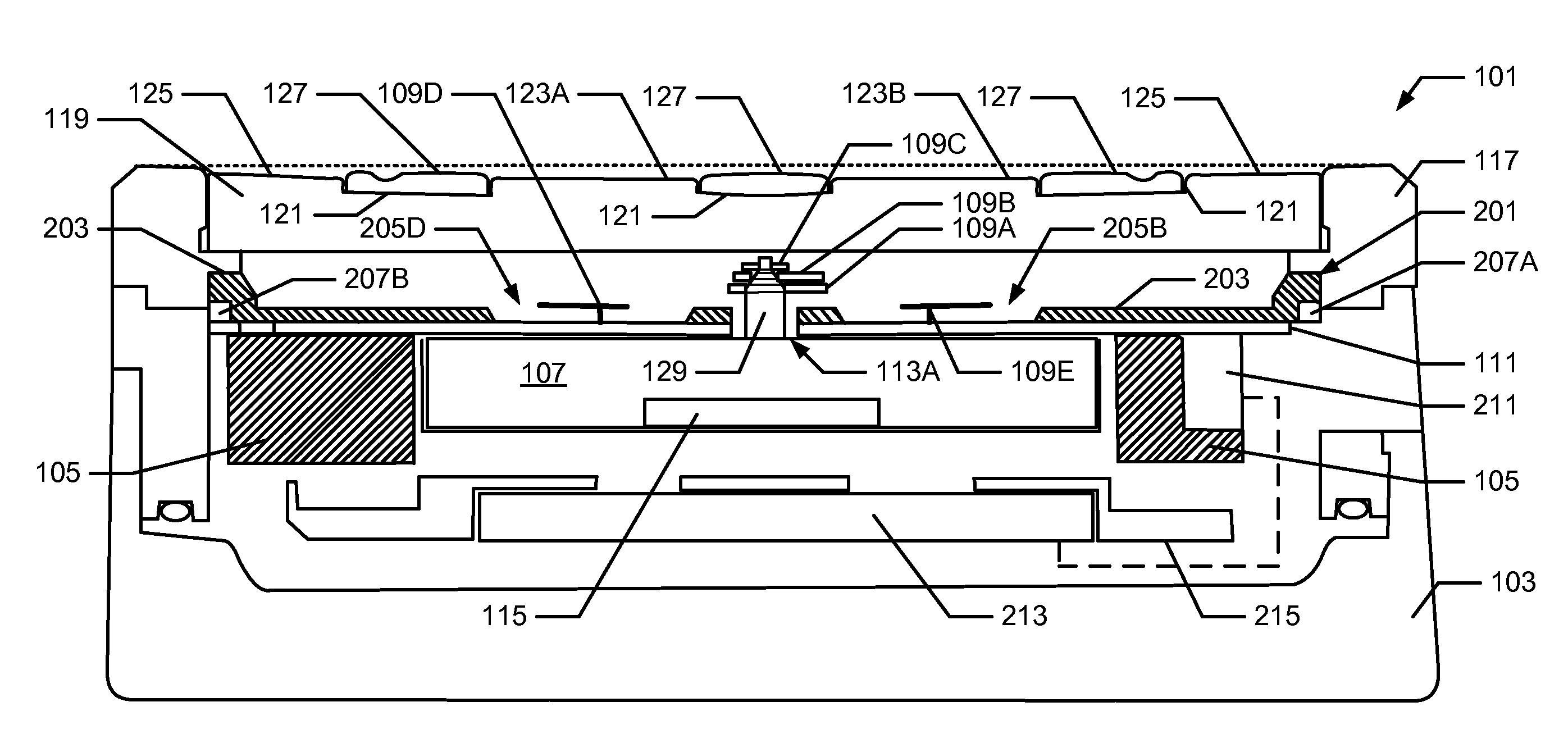
<figref idrefs="DRAWINGS">FIG. 1</figref> illustrates a cross-section of an example watch or other instrument according to the invention;
<figref idrefs="DRAWINGS">FIG. 2</figref> illustrates a perspective exploded view of an example crystal and bezel structure for an example instrument according to the invention; and
<figref idrefs="DRAWINGS">FIG. 3</figref> illustrates a perspective exploded view of an illumination system for an example instrument according to the invention.
The reader is advised that the drawings do not necessarily illustrate all of the elements of an instrument and/or the various features of the instrument to scale.
DETAILED DESCRIPTION
I. General Description of Watches and other Instruments in Accordance with Examples of the Invention
In the following description of various example structures in accordance with the invention, reference is made to the accompanying drawings, which form a part hereof, and in which are shown by way of illustration various example instrument assemblies in accordance with the invention. Additionally, it is to be understood that other specific arrangements of parts and structures may be utilized, and structural and functional modifications may be made without departing from the scope of the present invention. Also, while the terms “top,” “bottom,” “front,” “back,” “rear,” “side,” “underside,” “overhead,” and the like may be used in this specification to describe various example features and elements of the invention, these terms are used herein as a matter of convenience, e.g., based on the example orientations shown in the figures and/or the orientations in typical use. Nothing in this specification should be construed as requiring a specific three dimensional or spatial orientation of structures in order to fall within the scope of this invention.
Aspects of this invention relate to watches and other instruments that include a display panel and/or device, such as pedometers, compasses, GPS devices, telephones, PDAs, and other wrist-borne instruments or other portable electronic devices. In at least some examples of this invention, crystal assemblies for such instruments may include: (a) a bezel having a first surface; (b) a crystal engaged with the bezel, the crystal having a first surface and an opposite second surface, the first surface being positioned to lie below the first surface of the bezel and the second surface positioned below the bezel's first surface; and (c) a crystal guard located on the first surface of the crystal, wherein at least a portion of the crystal guard extends in a direction toward the first surface of the bezel and beyond the first surface of the crystal (e.g., such that at least some portion of the crystal guard extends to a location beyond and outside of the first surface of the crystal). If desired, the first surface of the crystal may be concave such that at least a portion of the first surface of the crystal is located between the first surface of the bezel and the second surface of the crystal (i.e., the first surface of the crystal lies below the uppermost surface of the bezel).
The crystal guard may be formed of a hard material, such as a metal, a hard plastic material, a ceramic material, a stone material, etc. Alternatively, if desired, the crystal guard may be formed of a flexible material, such as a foam material or other material that compresses somewhat under an incident force. Similarly, the bezel may be formed of a hard material, such as a metal, a hard plastic material, a ceramic material, a stone material, etc., or it may be formed of a flexible material, such as a foam material or other material that compresses somewhat under an incident force. If desired, either or both the crystal guard and the bezel may include indicia thereon, such as trademarks or logos, design elements, elements that assist in reading the instrument display (e.g., scales, numbers, letters, hour markings, minute markings, words, etc.), etc. As additional examples, if desired, the crystal guard and/or bezel (or at least some portions thereof) may be releasably mounted in the overall instrument structure, e.g., to allow removal and/or interchange, such as for repair, replacement, and/or personalization/customization purposes, etc.
In at least some example structures in accordance with the invention, the first surface of the crystal defines a recess, and the crystal guard may be positioned at least partially within this recess. The crystal guard may be secured to the first surface of the crystal (e.g., within the recess) in any desired manner without departing from this invention, such as via cements or adhesives, via a tight friction fit, via one or more mechanical connectors, via one or more retaining structures, via releasable connections (as mentioned above), via combinations thereof. As yet another example, if desired, the crystal guard may be integrally formed with the crystal structure, such as by a co-molding structure. In still other examples of this invention, the first surface of the crystal may define one or more recesses, and the first surface of the crystal may be formed to include one or more raised portions located within the recess(es). One or more crystal guards may be positioned within the recess(es), and the crystal guard(s) may be formed to include one or more apertures into which the various raised portions extend. Optionally, a recess may be positioned on the first surface of the crystal so as to define a raised annular ring of material around the crystal, and the crystal guard or guards may be sized and arranged such that they do not extend over and/or cover this raised annular ring.
Additional aspects of this invention relate to instruments that include crystal assemblies, e.g., of the various types described above. Such instruments may take the form of watches and other instruments that include display panels, such as pedometers, compasses, GPS devices, telephones, PDAs, audio/video playing equipment, and other wrist-borne instruments or other portable electronic devices.
Specific examples of instrument structures according to this invention are described in more detail below. The reader should understand that these specific examples are set forth merely to illustrate examples of the invention, and they should not be construed as limiting the invention.
II. Specific Examples of Watches and Other Instruments in Accordance with This Invention
A. The Instrument Assembly
<figref idrefs="DRAWINGS">FIG. 1</figref> illustrates an example of a watch <b>101</b> that may be implemented according to various examples of the present invention. <figref idrefs="DRAWINGS">FIG. 2</figref> illustrates an example crystal structure for such an instrument <b>101</b>, and <figref idrefs="DRAWINGS">FIG. 3</figref> illustrates an example illumination system for such an instrument. As seen in these figures, the watch <b>101</b> includes a casing <b>103</b>, a movement holder <b>105</b>, and a movement <b>107</b>. With this illustrated example, the watch <b>101</b> provides an analog display. Accordingly, the movement <b>107</b> in this example structure <b>101</b> drives one or more pinions to rotate a plurality of hands <b>109</b>. The watch <b>101</b> of this example structure includes three longer hands, namely: an hour hand <b>109</b>A, a minute hand <b>109</b>B, and a second hand <b>109</b>C. The watch <b>101</b> of this example structure also includes three smaller chronographic hands, namely: an hour hand <b>109</b>D, a minute hand <b>109</b>E, and a second hand <b>109</b>F. Any desired number of hands or other display indicating elements, and/or combinations of such hands or other elements, for any desired functions or combinations of functions, may be provided in a watch or other instrument structure <b>101</b> without departing from this invention.
As is well known in the art, the movement <b>107</b> rotates the hour hand <b>109</b>A so that it makes one complete revolution every 12 hours, and it rotates the hour hand <b>109</b>D one complete revolution every 24 hours to indicate the elapse of hours. Similarly, the movement <b>107</b> rotates the minute hands <b>109</b>B and <b>109</b>E so each makes one complete revolution every hour to indicate the elapse of minutes in an hour. The movement <b>107</b> also rotates the second hands <b>109</b>C and <b>109</b>F so that each makes one complete revolution every minute, to indicate the elapse of seconds in a minute. Conventionally, the movement <b>107</b> continuously drives the hands <b>109</b>A, <b>109</b>B and <b>109</b>F. The movement <b>107</b> also may be designed and structured to start and stop the operation of the hands <b>109</b>C, <b>109</b>D and <b>109</b>E in response to input from a user. In accordance with at least some examples of the invention, the movement <b>107</b> also may provide a date counter (not shown) that increments one value every 24 hour period, to indicate the passage of days in a month. Other arrangements and functions also are possible.
A movement case cover <b>111</b> is provided over the movement holder <b>105</b>. The movement case cover <b>111</b> protects the movement <b>107</b> from dust, debris and, with various examples of the invention, moisture. The movement case cover <b>111</b> defines apertures <b>113</b>A-<b>113</b>D, each corresponding to a pinion or connection stem (e.g., connection stem <b>129</b> in <figref idrefs="DRAWINGS">FIG. 1</figref>) that drives one of the hands <b>109</b>. Thus, the pinion or connection stem for each of the hands <b>109</b> passes through a corresponding aperture <b>113</b>A-<b>113</b>D to rotate its corresponding hand <b>109</b>. The movement case cover <b>111</b> of this example structure <b>101</b> also defines an aperture <b>113</b>E, corresponding to a date counter. In some examples of the invention, a date indicator simply may be viewed through the aperture <b>113</b>E. With still other examples of the invention, however, the date counter (when present) may have a raised portion that extends through the aperture <b>113</b>E or some other desired structure.
The movement case cover <b>111</b> may be formed of any desired material, such as brass. With some implementations of the invention, the surface of the movement case cover <b>111</b> that faces the hands <b>109</b> (i.e., the upper surface in <figref idrefs="DRAWINGS">FIGS. 1 and 3</figref>) may have a reflective appearance, as will be discussed in more detail below. With still other examples of the invention, the surface of the movement case cover <b>111</b> that faces the hands <b>109</b> may be painted, etched, and/or otherwise marked (or modified) to display indicators (e.g., indicator <b>131</b> in <figref idrefs="DRAWINGS">FIG. 3</figref>), as also will be discussed in more detail below.
With the illustrated implementation of the invention, the movement <b>107</b> is an electronic movement, such as a quartz movement. Accordingly, the watch <b>101</b> also includes a battery <b>115</b> for powering the operation of the movement <b>107</b>. With alternate examples of the invention, however, the movement <b>107</b> may be a mechanical movement that operates using an arrangement of springs and gears to store and release kinetic energy. A variety of both quartz and mechanical movements are well known in the art, and thus will not be detail in more detail here.
The watch <b>101</b> also includes a bezel <b>117</b>, which in turn holds a crystal <b>119</b>. The bezel <b>117</b> may be formed of a relatively hard material that will resist scratching and gouging, such as hard plastic or resin, aluminum, steel, titanium, or other metal. The bezel <b>117</b> also may be formed of a flexible material that will compress before registering a scratch or gouge, such as rubber. If desired, the bezel <b>117</b> may form a part of the case <b>103</b> and/or it may be removably mounted to other portions of the watch structure <b>101</b> (e.g., to allow removal and replacement, e.g., when damaged, for personalization/customization purposes, etc.), by mechanical connectors or in any other desired manner. The bezel <b>117</b> also may include indicia thereon, such as trademarks or logos, design elements, instrument display markings to convey information to the user (such as scales, numbers, letters, hour markings, minute markings, words, etc.), etc.
The crystal <b>119</b> may be formed of any desired transparent or semi-transparent material, such as sapphire, glass, clear acrylic, or clear polycarbonate. In the illustrated example of the invention, the crystal <b>119</b> is secured in the bezel <b>117</b> by an adhesive. With still other implementations of the invention, however, the crystal <b>119</b> may be secured in the bezel <b>117</b> by any desired means, such as by flanges, by threads, by welding, by press-fitting, etc. Optionally, an O-ring or gasket may be provided around the junction of the bezel <b>117</b> and the crystal <b>119</b>, e.g., to help prevent moisture or water from entering the instrument casing <b>103</b> via this junction.
In the illustrated example of the invention, the crystal <b>119</b> has a circular shape. With still other examples of the invention, however, the crystal <b>119</b> may have any desired shape, such as a rectangular, square, oval or irregular shape.
The surface of the crystal <b>119</b> facing away from the hands <b>109</b> is concave in this structure <b>101</b>, so that it does not extend past the surface of the bezel <b>117</b> facing away from the hands <b>109</b> (note the broken straight and planar line in <figref idrefs="DRAWINGS">FIG. 1</figref>, which helps to illustrate the overall concave nature of the top surface of the crystal <b>119</b>). Further, and as also illustrated in <figref idrefs="DRAWINGS">FIG. 2</figref>, the surface of the crystal <b>119</b> facing away from the hands <b>109</b> may have a topography that defines at least one recess <b>121</b>. With this illustrated example of the invention, the recess(es) <b>121</b> is (are) defined so that four non-recessed circular areas <b>123</b> remain in the central part of the crystal <b>119</b>. As seen in <figref idrefs="DRAWINGS">FIGS. 1 and 2</figref>, the non-recessed circular areas <b>123</b>A and <b>123</b>B correspond to the area traversed by a chronometer hands <b>109</b>D and <b>109</b>E, respectively. The third non-recessed circular area <b>123</b>C corresponds to the area traversed by a chronometer hand <b>109</b>F, while the fourth non-recessed circular area <b>123</b>D corresponds to the aperture <b>205</b>E in the light diffusion device <b>203</b> and the aperture <b>113</b>E in the movement cover <b>111</b> (e.g., for viewing the date counter). The recess(es) <b>121</b> is (are) defined so that the crystal <b>119</b> also has a non-recessed, ring-shaped area <b>125</b> encircling the perimeter of the crystal <b>119</b>. This non-recessed ring-shaped area <b>125</b> corresponds to an area of the display traversed by the ends of the hands <b>109</b>A-<b>109</b>C.
The watch <b>101</b> of this example structure also includes a crystal guard <b>127</b>, e.g., formed as a protective plate. The shape of the crystal guard <b>127</b> may be selected so as to generally match the shape of the recess <b>121</b>, e.g., so that the guard <b>127</b> defines a plurality of recesses or openings corresponding to the non-recessed areas <b>123</b> in the crystal <b>119</b>. Further, the guard <b>127</b> is positioned within the recess <b>121</b>. As seen in <figref idrefs="DRAWINGS">FIG. 1</figref>, however, the height of the guard <b>127</b> is taller than the depth of the recess <b>121</b>. Accordingly, the surface of the guard <b>127</b> facing away from the hands <b>109</b> (that is, the upper surface of the guard <b>127</b> as shown in <figref idrefs="DRAWINGS">FIGS. 1 and 2</figref>) extends beyond the upper surface of the crystal <b>119</b>. Like the bezel <b>117</b>, the guard <b>127</b> may be formed of a relatively hard material that will resist scratching and gouging, such as hard plastic or resin (optionally a transparent material), aluminum, steel, titanium, or other metal. The guard <b>127</b> also may be formed of a flexible material that will compress before registering a scratch or gouge, such as rubber. These features can help protect the crystal <b>119</b> from damage.
It should be appreciated that, while the illustrated example of the invention has only a single guard <b>127</b>, still other examples of the invention may employ multiple guards <b>127</b> that fit into the one or more recesses <b>121</b>. Still further, as noted above, some implementations of the invention may have a crystal <b>119</b> with multiple recesses <b>121</b>. One or more guards <b>127</b> can then be inserted into each recess. With the illustrated example of the invention, the guard <b>127</b> is fixed into the recess <b>121</b> of the crystal <b>119</b> using an adhesive. It should be appreciated, however, that other embodiments of the invention may employ any desired technique to fix the guard <b>127</b> into the recess <b>121</b>. For example, the crystal <b>119</b> may be co-molded onto the guard <b>127</b> so that the guard <b>127</b> defines the recess <b>121</b> when the crystal is formed, the guard <b>127</b> may be press-fit or friction fit into the recess <b>121</b>, retaining structures may be provided to hold the guard <b>127</b> in the recess, mechanical connectors may hold the guard <b>127</b> with respect to the recess <b>121</b>, etc.
If desired, the crystal guard <b>127</b> (or at least portions thereof) may be removably mounted to the crystal <b>119</b>, e.g., to allow removal and/or replacement, for example, when damaged, for personalization/customization purposes, etc. The crystal guard <b>127</b> may include indicia thereon, such as trademarks or logos, design elements, instrument display markings to convey information to the user (such as scales, letters, numbers, words, hour markings, minute markings, etc.), etc.
B. Illumination System
<figref idrefs="DRAWINGS">FIGS. 1 and 3</figref> also illustrate an illumination system <b>201</b> that can be implemented according to various examples of the invention. The illumination system <b>201</b> of this example structure <b>101</b> includes a light diffusion device <b>203</b> defining a plurality of apertures <b>205</b> and two light sources <b>207</b>. As seen in these figures, the light diffusion device <b>203</b> is positioned between the movement <b>107</b> and the hands <b>109</b>. With the illustrated example of the invention, the light diffusion device <b>203</b> is formed as a generally circular disk or plate, having a major surface that faces the hands <b>109</b> (i.e., the upper surface in <figref idrefs="DRAWINGS">FIGS. 1 and 3</figref>) and a major surface that faces the movement <b>107</b> (i.e., the lower surface in <figref idrefs="DRAWINGS">FIGS. 1 and 3</figref>). This light diffusion device <b>203</b> also has one or more minor side surfaces that may be arranged to extend between the major surfaces, e.g., substantially orthogonal to the surface that faces the hands <b>109</b>. The side surface(s) may produce a raised ledge appearance, as shown in <figref idrefs="DRAWINGS">FIGS. 1 and 3</figref>.
As previously noted, the light diffusion device <b>203</b> of this example structure <b>101</b> defines five separate apertures <b>205</b>A-<b>205</b>E. The aperture <b>205</b>A allows the pinions driving the hands <b>109</b>A-<b>109</b>C to pass through the light diffusion device <b>203</b> (see connection stem <b>129</b> in <figref idrefs="DRAWINGS">FIG. 1</figref>), while the apertures <b>205</b>B-<b>205</b>D provide space for the rotation of the chronographic hands <b>109</b>D-<b>109</b>F. With some examples of the invention, the aperture <b>205</b>E provides open and unobstructed viewing of a date counter. For implementations of the invention where the date counter has a raised portion, the aperture <b>205</b>E may allow the raised portion of the date counter to extend into or through the light diffusion device <b>203</b>.
With various implementations of the invention, the light diffusion device <b>203</b> is formed of a transparent or semi-transparent material that diffuses incident light. For example, the light diffusion device <b>203</b> may be formed of glass, acrylic, or a polycarbonate material, such as an optically-enhanced polycarbonate material. As will be discussed in more detail below, the surface of the light diffusion device <b>203</b> that faces the movement <b>107</b> may be formed with a varying topography, like a grating. As will also be discussed in more detail below, one or more surfaces of the light diffusion device <b>203</b> may be painted, etched, or otherwise marked to display indicators (see indicator <b>133</b> in <figref idrefs="DRAWINGS">FIG. 3</figref>). Such light diffusing polycarbonate materials are known and are commercially available.
With the illustrated implementation of the invention, light sources <b>207</b> are positioned on opposite sides of the light diffusion device <b>203</b>. More particularly, a first light source <b>207</b>A is positioned on one side of the light diffusion device <b>203</b> adjacent a minor surface oriented generally orthogonal to the surface that faces the hands <b>109</b>. A second light source <b>207</b>B is positioned on an opposite side of the light diffusion device <b>203</b>, also adjacent a minor surface oriented generally orthogonal to the surface that faces the hands <b>109</b>. It should be appreciated, however, that alternate embodiments of the invention may employ one or three or more light sources <b>207</b>. Also, one or more light sources <b>207</b> may alternately or additionally be placed adjacent to the lower surface of the diffusion device <b>203</b> (that is, the surface that that faces the movement <b>107</b>).
With the illustrated example of the invention, the lights sources <b>207</b> are light emitting diodes controlled through a printed circuit board <b>211</b>. The light sources <b>207</b> are powered by a light source battery <b>213</b> positioned in light source battery holder <b>215</b>. Of course, with alternate examples of the invention, the light sources <b>207</b> may be or may include any desired type of light emitting device, such as incandescent lights, plasma displays, or organic light emitting devices (OLEDs). With some implementations of the invention, the light sources <b>207</b> may activate only in response to input from a user (e.g., by a button press or other switch activation action). For still other implementations of the invention, however, the light sources <b>207</b> may activate in response to any desired stimulus, such as movement or input from an ambient light detector, on a periodic basis, such as between the hours of 7:00 PM and 7:00 AM, or may be continuously operational.
When the light sources <b>207</b> emit light, the light enters into the light diffusion device <b>203</b> and is propagated throughout the diffusion device in a direction parallel to the surface that faces the hands <b>109</b>. As the light propagates through the light diffusion device <b>203</b>, the light is emitted from the surface that faces the hands <b>109</b>, to thereby illuminate the hands <b>109</b> and the surrounding area (e.g., backlighting). If the diffusion device <b>203</b> covers a substantial amount of the area traversed by the hands <b>109</b>, as shown in <figref idrefs="DRAWINGS">FIGS. 1 and 3</figref>, the light emitted from the light diffusion device <b>203</b> will evenly illuminate the entire area traversed by the hands <b>109</b>.
As shown in <figref idrefs="DRAWINGS">FIGS. 1 and 3</figref>, the light diffusion device <b>203</b> may include one or more notched areas on its side surface(s) to receive the light source <b>207</b>. This arrangement allows the light to be directly (and efficiently) introduced into the light diffusion device <b>203</b>. Other arrangements are possible, however, without departing from this invention. For example, if desired, the light sources may be positioned at any desired location(s) in the overall instrument structure and “optically coupled” to the light diffusion device, e.g., using fiber optics, light pipes, or other light transmission systems. As another example, if desired, the light sources may be arranged at least partially beneath the light diffusion device <b>203</b> (and optionally transmit light into the light diffusion device <b>203</b> through its bottom surface). Other arrangements of the light sources with respect to the diffusion device or combinations of these arrangements also may be used without departing from this invention.
It should be appreciated that various structural features can be implemented with different embodiments of the invention to increase the amount of light emitted from the upper surface of the light diffusion device <b>203</b> (that is, the surface that faces the hands <b>109</b>). For example, as previously noted, the lower surface of the light diffusion device <b>203</b> can be formed with a varying topography. Depending upon the shape of the topography, the lower surface of the light diffusion device <b>203</b> may act as a diffraction grating to reflect light propagating in the light diffusion device <b>203</b> toward its upper surface. Still further, with various examples of the invention, the light diffusion device <b>203</b> may be formed with smaller and/or fewer apertures, or with no apertures at all. As yet another example, if desired, portions of the diffusion device <b>203</b> may be masked so as to allow light to be emitted therefrom only at selected locations.
In some example structures in accordance with this invention, the torque provided by the movement <b>111</b> to the chronographic hands <b>109</b>D-<b>109</b>F can be increased, thereby allowing the pinions rotating the hands <b>109</b>D-<b>109</b>F to be lengthened and the hands <b>109</b>D-<b>109</b>F to be positioned well above the upper surface of the light diffusion device <b>203</b>. In such arrangements, the apertures <b>205</b>B-<b>205</b>D can be reduced in size so as to have only the minimum diameter required to fit the pinions. With other embodiments of the invention, the light diffusion device <b>203</b> may define a recess around each aperture <b>205</b>B-<b>205</b>D to allow for rotation of the hands <b>109</b>D-<b>109</b>F. As another alternative, if the hands <b>109</b>D-<b>109</b>F are positioned sufficiently well above the upper surface of the light diffusion device <b>203</b>, the light diffusion device <b>203</b> may avoid any recesses. Reducing the area of the apertures will increase the propagation of light through the light diffusion device <b>203</b> and more evenly distribute the light emitted from the surface of the light diffusion device <b>203</b> that faces the hands <b>109</b>.
Alternately or additionally, the upper surface of the movement case cover <b>111</b> (or at least a portion thereof) may be formed of a reflective material. The upper surface of the movement case cover <b>111</b> will then reflect light emitted from the light diffusion device <b>203</b> back into the light diffusion device <b>203</b> and toward its upper surface. With some examples of the invention, a separate reflective material may be interposed (e.g., as a separate element) between the upper surface of the movement case cover <b>111</b> and the lower surface of the light diffusion device <b>203</b>. As yet an additional example, if desired, the movement case cover <b>111</b> can be omitted (e.g., and the light diffusion device <b>203</b> may act as this cover).
In some embodiments of the invention, indicators <b>133</b> may be painted, etched, or otherwise marked or mounted on the light diffusion device <b>203</b>, e.g., to form or partially form a dial or other display indicator. More particularly, indicia for determining the status of the instrument (e.g., a relative time or elapsed time indicated by the watch <b>101</b>) can be marked on the surface of the light diffusion device <b>203</b> that faces the movement <b>107</b>, on the surface of the light diffusion device <b>203</b> that faces the hands <b>109</b>, embedded within the light diffusion device <b>203</b> itself, or some combination thereof (shown generally at reference number <b>133</b> in <figref idrefs="DRAWINGS">FIG. 3</figref>). Alternately or additionally, if desired, one or more indicators or other indicia <b>131</b> can be painted, etched, or otherwise marked or mounted on the surface of the movement case cover <b>111</b> that faces the hands <b>109</b>, so that these indicators can be viewed through the light diffusion device <b>203</b>. Still further, indicia for determining the status of the instrument (e.g., a relative time or elapsed time indicated by the watch <b>101</b>) can be marked on the surface of the crystal <b>119</b> that faces away from the hands <b>109</b>, on the surface of the crystal <b>119</b> that faces toward the hands <b>109</b>, embedded within the crystal <b>119</b> itself, or some combination thereof. As yet additional examples, if desired, an indicator plate or dial may be provided below the diffusion device <b>203</b> or above the light diffusion device <b>203</b> (and below the hands, e.g., if this plate or dial is transparent or translucent, or at least mostly transparent or translucent) so that light from the diffusion device illuminates or backlights indicia included on the plate. With such arrangements, these indicia can easily be viewed when the light diffusion device <b>203</b> diffuses light from the light sources <b>207</b>.
As another example implementation of the invention, hour, minute, and second indicators (for the primary minute hand <b>109</b>B, the primary second hand <b>109</b>C, the chronographic hour hand <b>109</b>D, the chronographic minute hand <b>109</b>E, and the chronographic second hand <b>109</b>F) may be printed on the surface of the crystal <b>119</b> that faces the hands <b>109</b>, to provide a gauge or scale for motion of the hands <b>109</b>A-<b>109</b>C. Indicators for the primary hour hand <b>109</b>A, such as hour numbers “3”, “6”, “9”, and “12”, and an indicator arc (e.g., connecting the hour numbers “12” and “3”) may be marked on the surface of the surface of the light diffusion device <b>203</b> that faces the hands <b>109</b>. Still further, supplemental indicators may be marked on the surface of the bezel <b>117</b> that faces away from the hands <b>109</b> and/or the surface of the crystal guard <b>127</b> (if any) that faces away from the hands <b>109</b> to provide a further gauge or scale for motion of the hands <b>109</b>D-<b>109</b>F. Thus, as the various hands <b>109</b> rotate on their respective pinions, they pass over or by corresponding indicia on the light diffusion device <b>203</b>, the crystal <b>119</b>, the crystal guard <b>127</b>, and/or the bezel <b>117</b> to show the passage of time and/or to provide information to the user. Together, the hands <b>109</b> and the indicia formed by the indicators make up the display for the watch <b>101</b>.
It should be noted that the arrangement of the indicia on different portions of the watch <b>101</b> may be selected to determine which indicia will be visible under certain conditions. For example, by placing the hour numbers “3”, “6”, “9”, and “12” and the indicator arc on the surface of the light diffusion device <b>203</b> facing the hands <b>109</b>, these indicia may be made so as to be relatively invisible when the light diffusion device <b>203</b> is not diffusing light from the light sources <b>207</b>. When the light sources <b>207</b> are activated, however, and their light is diffused through the light diffusion device <b>203</b>, these indicia may become more visible along with any indicia included on the crystal <b>119</b> or other locations. Of course, it will be appreciated that multiple light diffusion devices <b>203</b>, together with one or more associated light sources <b>207</b>, can be stacked or otherwise layered to allow various indicia to be viewed under different circumstances.
III. Conclusion
While the invention has been described with respect to specific examples including presently preferred modes of carrying out the invention, those skilled in the art will appreciate that there are numerous variations and permutations of the above described systems and techniques that fall within the spirit and scope of the invention as set forth in the appended claims.
Contents5
5 sheets
Sheet 1 Sheet 2 Sheet 3 Sheet 4 Sheet 5
Every citation, both ways
| Document | Relation | Office | Cited during |
|---|---|---|---|
| US2011255376A1 | Cited by | United States of America | Pre-grant |
| US3701900A | Cites | United States of America | Search report |
| US4175444A | Cites | United States of America | Search report |
| US4835750A | Cites | United States of America | Search report |
| US4837756A | Cites | United States of America | Search report |
| US5034932A | Cites | United States of America | Search report |
| US5070431A | Cites | United States of America | Search report |
| US5138590A | Cites | United States of America | Search report |
| US5442602A | Cites | United States of America | Search report |
| US5546888A | Cites | United States of America | Search report |
| US5638342A | Cites | United States of America | Search report |
| US6618328B1 | Cites | United States of America | Search report |
| US6729738B2 | Cites | United States of America | Search report |
| US6731351B2 | Cites | United States of America | Search report |
| US6762976B1 | Cites | United States of America | Search report |
| US6791905B1 | Cites | United States of America | Search report |
| US7038976B2 | Cites | United States of America | Search report |
| US7433275B2 | Cites | United States of America | Search report |
| US7553037B2 | Cites | United States of America | Search report |
| US7654732B2 | Cites | United States of America | Search report |
2 priority claims, no other members on record
Priority claims2
| Document | Office | Kind | Date |
|---|---|---|---|
| 1600508 | United States of America | A | |
| US20080016005 | – | – | – |
33 transactions on the USPTO file
Allowed after 1 non-final rejection.
- Non-final rejections
- 1
- Final rejections
- 0
- RCEs
- 0
- Appeals
- 0
Over time
Point at a mark for the transactionTransactions
| Event | Code | |
|---|---|---|
| Payment of Maintenance Fee, 8th Year, Large EntityM1552 | M1552 | |
| Correspondence Address ChangeC.ADB | C.ADB | |
| Recordation of Patent Grant MailedPGM/ | PGM/ | |
| Patent Issue Date Used in PTA CalculationAllowedPTAC | PTAC | |
| Issue Notification MailedAllowedWPIR | WPIR | |
| Dispatch to FDCD1935 | D1935 | |
| Application Is Considered Ready for IssuePILS | PILS | |
| Issue Fee Payment VerifiedN084 | N084 | |
| Issue Fee Payment ReceivedIFEE | IFEE | |
| Mail Notice of AllowanceAllowedMN/=. | MN/=. | |
| Notice of Allowance Data Verification CompletedAllowedN/=. | N/=. | |
| Case Docketed to Examiner in GAUDOCK | DOCK | |
| Date Forwarded to ExaminerFWDX | FWDX | |
| Response after Non-Final ActionA... | A... | |
| Mail Non-Final RejectionNon-final rejectionMCTNF | MCTNF | |
| Non-Final RejectionNon-final rejectionCTNF | CTNF | |
| PG-Pub Issue NotificationPG-ISSUE | PG-ISSUE | |
| Case Docketed to Examiner in GAUDOCK | DOCK | |
| Decision Made by Classification DivisionTI1052 | TI1052 | |
| Request for Classification Division DecisionTI1054 | TI1054 | |
| Transfer Inquiry to GAUTI1050 | TI1050 | |
| IFW TSS Processing by Tech Center CompleteTSSCOMP | TSSCOMP | |
| Application Dispatched from OIPEOIPE | OIPE | |
| Sent to Classification ContractorPGPC | PGPC | |
| Filing Receipt - UpdatedFLRCPT.U | FLRCPT.U | |
| Application Is Now CompleteCOMP | COMP | |
| Payment of additional filing fee/PreexamFLFEE | FLFEE | |
| A statement by one or more inventors satisfying the requirement under 35 USC 115, Oath of the ApplicOATHDECL | OATHDECL | |
| Notice Mailed--Application Incomplete--Filing Date AssignedINCD | INCD | |
| Filing ReceiptFLRCPT.O | FLRCPT.O | |
| Cleared by OIPE CSRL194 | L194 | |
| IFW Scan & PACR Auto Security ReviewSCAN | SCAN | |
| Initial Exam Team nnIEXX | IEXX |
9 legal events, as the office reported them to INPADOC
Over the term
Point at a mark for the eventEvents
| Event | Code | |
|---|---|---|
| Lapsed due to failure to pay maintenance feeLapsedFP | FP | |
| Lapse for failure to pay maintenance feesLapsedLAPS | LAPS | |
| Information on status: patent discontinuationSTCH | STCH | |
| Fee payment procedureFEPP | FEPP | |
| Maintenance fee paymentMAFP | MAFP | |
| Fee paymentFPAY | FPAY | |
| Information on status: patent grantGrantedSTCF | STCF | |
| Information on status: patent grantGrantedSTCF | STCF | |
| AssignmentAS | AS |
Numbers
- Publication
- 07857504
- Publication, DOCDB
- 7857504
- Publication, EPODOC
- US7857504
- Application
- 12016005
- Application, DOCDB
- 1600508
- Application, EPODOC
- US20080016005
Titles
- English
- Crystal display shielded by one or more protective guards
Patent term adjustment
- A delay
- +420 daysthe office missed an examination deadline
- Applicant delay
- −60 days
- Net adjustment
- 360 days
Classification
- CPC, 4
- G04B39/006
- G04B19/28
- G04B37/0008
- G04B39/00
- IPC, 2
- G04B39 00
- G04B37 00
- USPC, 3
- 368286000
- 116305000
- 368294000