Wireless headset for communications device
Summary by NHIP
Wireless Half-Duplex Headset System
The apparatus wirelessly connects a headset to a half-duplex radio to control transmission modes and convey audio. A switch on the headset body sends a first signal to an adapter, which then generates a second signal to force the radio into transmit mode.
Claim Score by NHIP
Abstract
Disclosed herein is a communications system implementing a headset wirelessly connected to a half-duplex communications device, such as a two-way radio or a radio-simulating cellular phone. The headset may incorporate a transmit/receive switch wherein a transmit signal is wirelessly transmitted from the headset to the communications device to direct the communications device to enter into a transmit mode. Alternatively, a wireless transmit/receive switch may be implemented separately from the wireless headset, where the wireless transmit/receive switch may be positioned in the proximity of the communications device and the headset and may be engaged by a user to direct the communications device to enter a transmit mode.
Term
Term ended
Expired 21 April 2024, 2.4 years ago.
- Priority
- Filed
- Granted
- Expired
- Today
14 claims: 1 independent, 13 dependent
- 1Broadest claimClaim Score 41, average(NHIP)An apparatus for wirelessly communicating audio information to and from a half-duplex radio, the apparatus comprising:an adapter for connection to a portable half-duplex radio, and a wireless headset for wirelessly communicating information to the adapter;wherein said wireless headset comprises: a body to be worn on a user's head;a speaker assembly included in the body to output audio information to the user;a microphone assembly included in the body to receive audio information from the user;a switch positioned on the body;an encoder to convert an analog signal representative of the audio information from the user to digital signal;a processor connected to the encoder to packetize the digital signal;and a transceiver to wirelessly transmit a first transmit mode signal representative of an engagement of the switch to the adapter and to wirelessly transmit the packetized digital signal of the audio information;and said adapter comprises: an interface for connection to the portable half-duplex radio;a transceiver to receive the first transmit mode signal directly from the wireless headset;and a processor connected to the interface to provide a second transmit mode signal to the half-duplex radio upon receipt of the first transmit mode signal, the second transmit mode signal for causing the half-duplex radio to enter a half-duplex transmission mode.
57 paragraphs in 6 sections, as filed
CROSS-REFERENCE TO RELATED APPLICATIONS
0001The present invention claims benefit of U.S. patent application Ser. No. 60/503,949, filed Sep. 19, 2003 and entitled “Wireless Headset for Two-Way Radios” and U.S. patent application Ser. No. 60/527,776, filed Dec. 9, 2003 and entitled “Wireless Headset for Communication Device,” the entireties of which are incorporated by reference herein.
FIELD OF THE INVENTION
0002The present invention relates generally to half-duplex communications and more particularly to utilizing a push-to-talk (PTT) feature in a wireless headset.
BACKGROUND OF THE INVENTION
0003Half-duplex communications devices, such as two-way radios (or “walkie-talkies”) and cellular phones having a half-duplex or similar service, such as the DIRECT CONNECT® cellular walkie-talkie service offered by Nextel Communications, Inc. of Reston, Va. or the Push to Talk Group Calling feature offered by Verizon Wireless of Bedminster, N.J., frequently are used to facilitate communications between mobile users, such as emergency personnel and construction workers. Because half-duplex communications devices generally are not configured to support simultaneous two-way communications, one or more mechanisms typically are implemented to help ensure that the half-duplex device is in a transmit mode only at the appropriate times. One such mechanism includes a voice operated (VOX) feature whereby a user's voice or other sound triggers the communications device to enter a transmit mode. Another mechanism includes a push-to-talk (PTT) button which places the communications device in a transmit mode while pressed or engaged and returns the communications device to a receive mode when the PTT button is released or disengaged. Thus, while the VOX feature benefits from not requiring the user to manipulate a button to switch the communications device between the transmit and receive mode, the VOX feature typically fails to operate accurately or correctly in noisy environments as the VOX feature often inadvertently interprets loud noises as a voice signal and therefore needlessly places the communications device in transmit mode. Accordingly, the use of a PTT button is frequently implemented for use in noisy environments.
0004Conventional implementations of PTT buttons (i.e., transmit/receive switches) are not without their drawbacks. For one, the location of the PTT button often causes significant inconvenience to the user. In many instances, the PTT button is located on the communications device which in turn is often placed about the user's body, thereby requiring the user to grasp for the communications device to engage the PTT button. Alternatively, some conventional implementations place the PTT button on a wire connecting a headset to the communications device. While this location for the PTT button may make it somewhat easier to quickly locate the PTT button, it will be appreciated that the wire is likely to become entangled with the user or with other equipment in the proximity due to its length and location.
0005Accordingly, improved techniques for implementing a PTT button functionality in a half-duplex communications device would be advantageous.
SUMMARY OF THE INVENTION
0006The present invention mitigates or solves the above-identified limitations in known solutions, as well as other unspecified deficiencies in known solutions. A number of advantages associated with the present invention are readily evident to those skilled in the art, including economy of design and resources, transparent operation, cost savings, etc.
0007In accordance with one embodiment of the present invention, a wireless headset is provided. The wireless headset comprises a switch for indicating a provision of audio information for transmission and means for wirelessly transmitting a signal representative of an engagement of the switch.
0008In accordance with another embodiment of the present invention, an apparatus is provided. The apparatus comprises an interface operably connected to a half-duplex communications device, a wireless interface; means for receiving a first transmit mode signal via the wireless interface, the transmit mode signal indicating a provision of audio information for transmission by the half-duplex communications device, and means for providing a second transmit mode signal to the half-duplex communications device via the interface to direct the half-duplex communications device to switch to a transmit mode.
0009In accordance with yet another embodiment of the present invention, a system is provided. The system comprises a half-duplex communications device and a headset wirelessly connected to the half-duplex communications device. The headset is adapted to wirelessly transmit a transmit mode signal-for reception by the half-duplex communications device, the transmit mode signal indicating a provision of audio information by the headset for transmission by the half-duplex communications device. The half-duplex communications device is adapted to transmit at least a portion of the audio information based at least in part upon receipt of the transmit mode signal.
0010In accordance with an additional embodiment of the present invention, a system is provided. The system comprises a half-duplex communications device, a transmit switch assembly wirelessly connected to the half-duplex communications device and a headset wirelessly connected to the half-duplex communications device. The transmit switch assembly is adapted to wirelessly transmit a transmit mode signal for reception by the half-duplex communications device, the transmit mode signal indicating a provision of audio information by the headset for transmission by the half-duplex communications device. The half-duplex communications device is adapted to transmit at least a portion of the audio information based at least in part upon receipt of the transmit mode signal.
0011Still further features and advantages of the present invention are identified in the ensuing description, with reference to the drawings identified below.
BRIEF DESCRIPTION OF THE DRAWINGS
0012The purpose and advantages of the present invention will be apparent to those of ordinary skill in the art from the following detailed description in conjunction with the appended drawings in which like reference characters are used to indicate like elements, and in which:
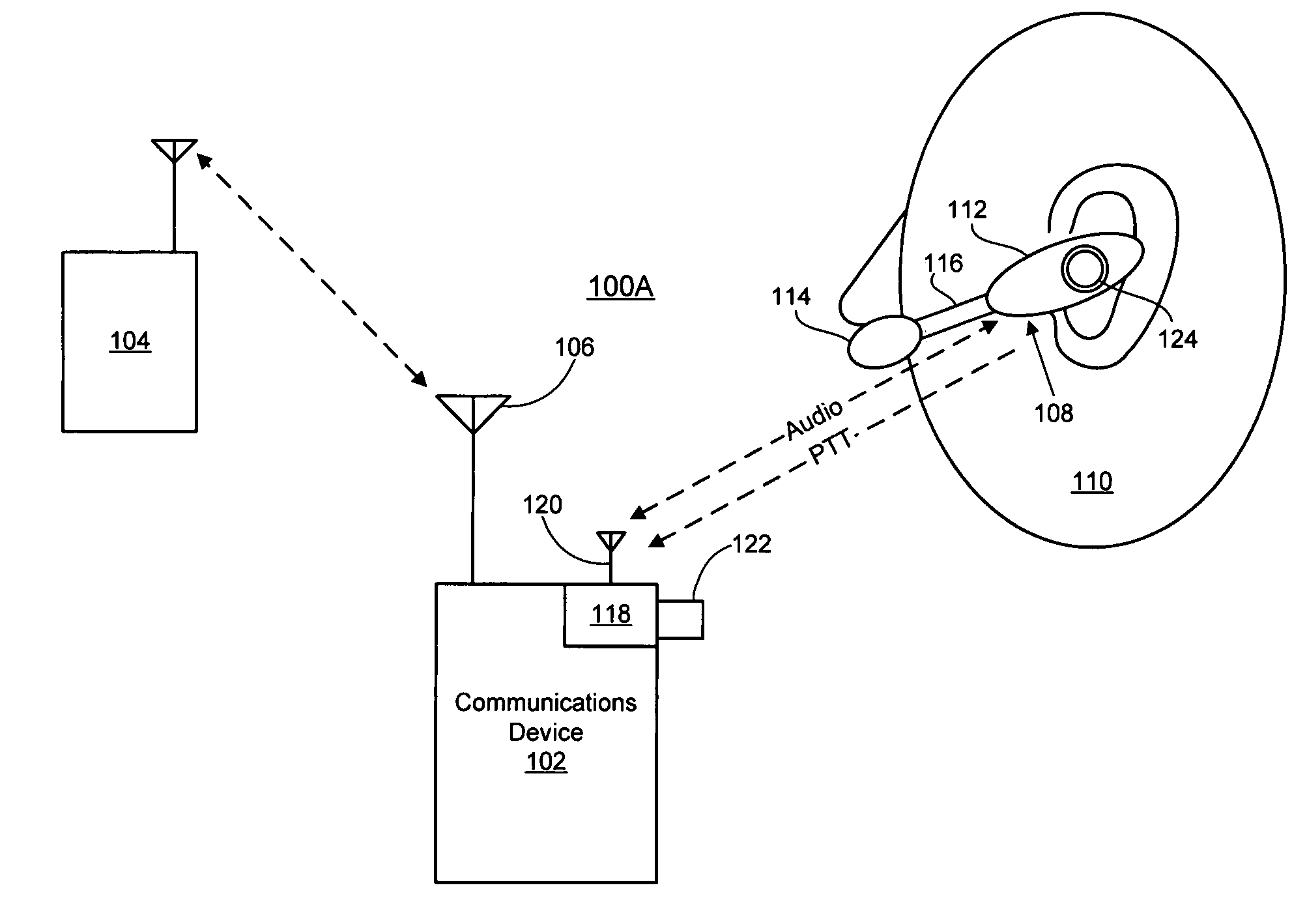
0013<figref idref="DRAWINGS">FIGS. 1A–1C</figref> are schematic diagrams of exemplary wireless communications systems implementing wireless headsets in accordance with at least one embodiment of the present invention.
0014<figref idref="DRAWINGS">FIGS. 2A–2G</figref> are schematic diagrams illustrating exemplary placements of a transmit/receive switch in conjunction with a wireless headset in accordance with at least one embodiment of the present invention.
0015<figref idref="DRAWINGS">FIG. 3</figref> is a schematic diagram of an exemplary wireless headset in accordance with at least one embodiment of the present invention.
0016<figref idref="DRAWINGS">FIG. 4</figref> is a schematic diagram of an exemplary wireless adaptor for a communications device in accordance with at least one embodiment of the present invention.
0017<figref idref="DRAWINGS">FIG. 5</figref> is a schematic diagram of an exemplary wireless transmit/receive switch assembly in accordance with at least one embodiment of the present invention.
0018<figref idref="DRAWINGS">FIGS. 6 and 7</figref> are diagrams illustrating exemplary push-to-talk engagement techniques in accordance with at least one embodiment of the present invention.
0019<figref idref="DRAWINGS">FIGS. 8A–8D</figref> are perspective views of an exemplary implementation of a wireless headset in accordance with at least one embodiment of the present invention.
0020<figref idref="DRAWINGS">FIG. 9</figref> is a perspective view of an exemplary implementation of a wireless adapter in accordance with at least one embodiment of the present invention.
DETAILED DESCRIPTION OF THE INVENTION
0021The following description is intended to convey a thorough understanding of the present invention by providing a number of specific embodiments and details involving the communication of information using multiple wireless channels. It is understood, however, that the present invention is not limited to these specific embodiments and details, which are exemplary only. It is further understood that one possessing ordinary skill in the art, in light of known systems and methods, would appreciate the use of the invention for its intended purposes and benefits in any number of alternative embodiments, depending upon specific design and other needs.
0022For ease of illustration, the present invention is described herein in the context of a half-duplex communications system wherein a wireless channel is reserved for the transmission of information through the use of a PTT mechanism. However, using the guidelines provided herein, the present invention also may be implemented in pseudo-half-duplex communications systems, such as, for example, the DirectConnect® cellular phone feature offered by Nextel Communications of Reston, Va., or other communications systems wherein a PTT mechanism or similar transmit/receive switch mechanism is used to reserve a wireless channel for the transmission of information. Accordingly, reference herein to half-duplex includes true half-duplex and other similar communications techniques unless otherwise noted.
0023Referring now to <figref idref="DRAWINGS">FIGS. 1A–1C</figref>, exemplary half-duplex systems <b>100</b>A, <b>100</b>B and <b>100</b>C are illustrated in accordance with at least one embodiment of the present invention. System <b>100</b>A includes a communications device <b>102</b> (e.g., a half-duplex radio or cellular phone) in communication with another communications device <b>104</b>. Communications between the devices <b>102</b> and <b>104</b> may be half-duplex transmissions and may be transmitted wirelessly via an antenna <b>106</b> or may be transmitted via a conductive wire, fiber optic cable, and the like.
0024In at least one embodiment, a wireless headset <b>108</b> is utilized to facilitate the transmission of audio information and other information (e.g., video information) between the communications device <b>102</b> and a user <b>110</b>. As discussed below with reference to <figref idref="DRAWINGS">FIGS. 2A–2C</figref>, the headset <b>108</b> may be implemented as an earbud-type or ear-clip type headset which may utilize a relatively small headset body <b>112</b> operably connected to an earbud speaker (not shown) for outputting audio information and a microphone assembly <b>114</b> for inputting audio information (such as the vocalizations of the user <b>110</b>). As depicted in the illustrated embodiment, the microphone assembly <b>114</b> may be operably connected to the headset body <b>112</b> via a boom <b>116</b>. Alternatively, the microphone assembly <b>114</b> may be implemented on a wire connected to the headset body <b>112</b> which may be clipped to the clothing of the user <b>110</b>, for example. The microphone assembly <b>114</b> may include any of a variety of microphones, including, but not limited to, throat microphones, boom microphones, bone induction microphones (i.e., microphones placed in the ear canal which pick up audio signals via vibrations in the ear canal), and the like.
0025As illustrated in greater detail with reference to <figref idref="DRAWINGS">FIGS. 2D–2G</figref>, the headset <b>108</b> alternately may be implemented as a headband-type headset having one or two ear pads or cups connected via one or more bands that encircle at least part of the head or neck of the user <b>110</b>.
0026The headset <b>108</b> preferably is configured to wirelessly communicate audio information to and from the communications device <b>102</b>. Accordingly, as discussed in detail below, the headset <b>108</b> may utilize a wireless interface comprising at least an antenna and a transceiver to transmit and receive analog and/or digital signals representative of audio information or other information. Accordingly, the communications device <b>102</b> may include a module capable of wirelessly communicating with the headset <b>108</b> via, for example, the antenna <b>106</b>, or a wireless adapter <b>118</b> may be used to wirelessly relay information between the headset <b>108</b> and the communications device <b>102</b> via, for example, the antenna <b>106</b> or a separate antenna <b>120</b>. To illustrate, the wireless adapter <b>118</b> may include a device that connects to a commercial radio handset (one embodiment of the communications device <b>102</b>) via, for example, a socket or jack conventionally used to connect the radio handset to a wired headset. Audio information from the communications device <b>102</b> may be provided to the wireless adapter <b>118</b> via the socket or jack and the wireless adapter <b>118</b> may transmit the audio information wirelessly for reception by the headset <b>108</b>. Conversely, audio information may be transmitted wirelessly from the headset to the wireless adapter <b>118</b> and the wireless adapter <b>118</b> then may provide an electric or optical signal representative of the audio information to the communications device <b>102</b> via the socket or jack.
0027As noted above, the communications device <b>102</b> may be configured to operate in a half-duplex communications mode and may rely on some type of transmission indication to indicate when the user <b>110</b> has audio information to transmit to the communications device <b>104</b>. Conventionally, the transmission indication is supplied through the use of a transmit/receive switch positioned on or near the communications device which provides a signal that indicates that the transmission medium is reserved for the transmission of information by the communications device. Accordingly, in at least one embodiment, a transmit/receive switch is implemented to provide such a transmission indication, where the transmit/receive switch may include, for example, a push button, a toggle switch, a slide switch, a capacitive switch, and the like. The transmit/receive switch may be positioned on or near the communications device <b>102</b>, such as, for example, the transmit/receive switch <b>122</b> connected to or implemented as part of the wireless adapter <b>118</b>. Alternatively, the transmit/receive switch may be positioned on or operably connected to the wireless headset <b>108</b>, such as, for example, the transmit/receive switch <b>124</b> positioned on the body <b>112</b> of the headset <b>108</b>. To illustrate, the transmit/receive switch could be positioned on a side of the body <b>112</b> of the headset <b>108</b> that is facing or resting against the user's head such that the user <b>110</b> may press the body <b>112</b> of the headset <b>108</b> against the user's head to engage the transmit/receive switch.
0028In instances where the transmit/receive switch <b>124</b> is positioned on or connected to the wireless headset <b>108</b>, the headset <b>108</b> may be configured to wirelessly transmit a signal representative of an engagement of the transmit/receive switch <b>124</b> to the wireless adapter <b>118</b>, or, alternatively, to the communications device <b>102</b>. Upon receipt of the signal representation of the engagement of the transmit/receive switch <b>124</b>, the wireless adapter <b>118</b> may provide a corresponding signal to the communications device <b>102</b> to cause the communications device <b>102</b> to enter a transmit mode for the subsequent audio information provided from the headset <b>108</b>.
0029Referring to <figref idref="DRAWINGS">FIG. 1B</figref>, an alternative implementation of a transmit/receive switch feature is illustrated as system <b>100</b>B. Rather than, or in addition to, a transmit/receive switch positioned on the headset <b>108</b> or the wireless adapter <b>118</b>, in one embodiment a wireless transmit/receive switch assembly <b>130</b> may be employed to provide a PTT-type transmit mode indication. Accordingly, the transmit/receive switch assembly <b>130</b> may be located in any of a number of useful locations within range of the communications device <b>102</b> without requiring one or more wires that may become entangled or otherwise hinder the user <b>110</b>. In the illustrated example, the transmit/receive switch assembly <b>130</b> includes a transmit/receive switch <b>132</b> that may be engaged by the user <b>110</b> to indicate that audio information is to be transmitted, a power supply such as a battery (not shown) and processing hardware and software adapted to wirelessly transmit a PTT-type transmit mode indication to the wireless adapter <b>118</b> or the communications device <b>102</b> via, for example, an antenna <b>134</b> when the user <b>110</b> engages the transmit/receive switch <b>132</b>.
0030Moreover, in at least one embodiment, the headset <b>108</b> may be configured to receive the transmit mode signal from the transmit/receive switch assembly <b>130</b> to determine whether the transmit/receive switch <b>134</b> has been engaged. If not engaged, the headset <b>108</b> may forgo the transmission of any audio information input by the microphone assembly <b>114</b> to minimize power consumption and/or to minimize or eliminate unintended transmissions such as, for example, when the user <b>110</b> is talking but does not intend to transmit via the communications device <b>102</b>.
0031In addition to implementing a transmit/receive switch to enable a PTT-type functionality, the headset <b>108</b> may further be VOX enabled and therefore may implement a VOX-PTT switch to enable the user <b>110</b> to switch between VOX-type transmission handling and PTT-type transmission handling.
0032Referring to <figref idref="DRAWINGS">FIG. 1C</figref>, another exemplary embodiment of the headset <b>108</b> is illustrated. In the exemplary system <b>100</b>C, a wireless microphone assembly <b>144</b> may be used to input and communicate audio information from the user <b>110</b> to the communications device <b>102</b>. The wireless microphone assembly <b>144</b> preferably is adapted to detect and convert audio signals into a corresponding electrical signal and wirelessly transmit an analog or digital form of the electric signal to the adapter <b>118</b> or the communications device <b>102</b>. The wireless microphone assembly <b>144</b> may include any of a variety of attachment mechanisms, such as straps, hook-and-loop fasteners, adhesives, magnets, etc., so that the wireless microphone assembly <b>144</b> may be fastened or otherwise positioned on or in proximity to the user <b>110</b>. For example, as illustrate, the wireless microphone assembly <b>144</b> may implement a throat microphone placed in contact with the throat of the user <b>110</b> using one or more straps.
0033Referring now to <figref idref="DRAWINGS">FIGS. 2A–2E</figref>, various exemplary configurations of the wireless headset <b>108</b> are illustrated in accordance with at least one embodiment of the present invention. <figref idref="DRAWINGS">FIG. 2A</figref> illustrates a wireless earbud-type or earclip-type headset <b>200</b>A wherein a transmit/receive switch <b>202</b> is positioned on a body <b>204</b> of the headset <b>200</b>A. In this instance, the transmit/receive switch <b>202</b> preferably is positioned to be substantially coaxial with the ear canal (not shown) of the user <b>110</b> to prevent excess torque from moving the headset <b>200</b>A or causing the headset <b>200</b>A to twist out of the user's ear. However, in some instances, the placement of the headset <b>200</b>A may be relatively secure and/or the transmit/receive switch <b>202</b> may be relatively sensitive to touch (e.g., a capacitive button) such that the transmit/receive switch <b>202</b> may be positioned elsewhere on the body <b>204</b>, such as, for example, on the top, side, or bottom of the body <b>204</b>.
0034<figref idref="DRAWINGS">FIG. 2B</figref> illustrates a wireless earbud-type or earclip-type headset <b>200</b>B wherein a transmit/receive switch <b>206</b> is positioned on a microphone assembly <b>208</b>, where the microphone assembly <b>208</b> may be connected to the body <b>204</b> via a boom <b>210</b>. In such instances, a transmit/receive switch <b>206</b> relatively sensitive to touch preferably is employed so that a minimum amount of force may be employed by the user <b>110</b> to engage the transmit/receive switch <b>206</b>.
0035Rather than positioning the transmit/receive switch directly on the headset, <figref idref="DRAWINGS">FIG. 2C</figref> illustrates an exemplary embodiment wherein a transmit/receive switch <b>212</b> is implemented as part of a transmit/receive switch assembly <b>214</b> connected to the main portion of an earbud-type or earclip-type headset <b>200</b>C via at least one wire lead <b>216</b> which may be used to signal the headset <b>200</b>C when the transmit/receive switch <b>212</b> is engaged. The transmit/receive switch assembly <b>214</b> may be clipped to some object on the user <b>110</b>, such as, for example, a collar of the user's shirt or a helmet or hat worn by the user.
0036Although <figref idref="DRAWINGS">FIGS. 2A–2C</figref> depict exemplary configurations of a transmit/receive switch on a wireless headset <b>108</b>, the present invention is not limited to these configurations. To illustrate, in one embodiment, the transmit/receive switch may be positioned on an interior side of the headset <b>108</b> and placed in contact with, or next to, the face or ear of the user <b>110</b> such that when the user <b>110</b> places pressure on the distal side of the headset <b>108</b>, the headset <b>108</b> is pressed closer to the face or ear of the user <b>110</b>, thereby engaging the transmit/receive switch. As another example, the speaker of the headset <b>108</b> may be implemented as a ear piece that is inserted in or near the ear canal of the user <b>110</b> (as illustrated with reference to <figref idref="DRAWINGS">FIGS. 8A–8D</figref>) and the transmit/receive switch may be integrated into the connection between the ear piece and the body of the headset <b>108</b> such that when the user <b>110</b> places pressure on the body of the headset <b>108</b> in the direction of the user's head, the connection is compressed, thereby engaging the transmit/receive switch. Using the guidelines provided herein, those skilled in the art may implement various transmit/receive switch positions and configurations without departing from the spirit or the scope of the present invention.
0037As illustrated in <figref idref="DRAWINGS">FIGS. 2D–2G</figref>, the wireless headset <b>108</b> alternatively may be implemented as a headband-type headset having a microphone assembly <b>218</b> one or two earpads <b>220</b> connected via one or more headbands <b>222</b>A or <b>222</b>B that may be positioned over and/or behind the head of the user <b>110</b>. <figref idref="DRAWINGS">FIG. 2D</figref> illustrates an exemplary headband-type headset <b>200</b>D wherein a transmit/receive switch <b>224</b> may be positioned on the earpad <b>220</b>. However, because the earpad <b>220</b> is larger and more secure than the earbud-type microphones described above, a more substantial transmit/receive switch may be used, as it is less likely that the user <b>110</b> is likely to dislodge the earpad <b>220</b> when engaging the transmit/receive switch <b>224</b>. <figref idref="DRAWINGS">FIG. 2E</figref> illustrates an exemplary headband-type headset <b>200</b>E wherein a transmit/receive switch <b>226</b> is positioned on a headband <b>222</b>A secured over the top of the user's head. Similarly, <figref idref="DRAWINGS">FIG. 2F</figref> illustrates an exemplary headband-type headset <b>200</b>F wherein a transmit/receive switch <b>228</b> is positioned on a headband <b>222</b>B secured behind the user's head. <figref idref="DRAWINGS">FIG. 2G</figref> illustrates an exemplary headband-type headset <b>200</b>G wherein a transmit/receive switch <b>230</b> is implemented as part of a transmit/receive switch assembly <b>232</b> and operably connected to the main portion of the headset <b>200</b>G via one or more wire leads <b>234</b>.
0038Referring now to <figref idref="DRAWINGS">FIG. 3</figref>, an exemplary functional implementation of the wireless headset <b>108</b> is illustrated in accordance with at least one embodiment of the present invention. In the illustrated example, audio information and other information may be transmitted from and received by the headset <b>108</b> in a packetized form. Accordingly, audio information from the user <b>110</b> (such as vocalizations from the user <b>110</b>) are received by a microphone assembly <b>302</b> and converted to a representative analog signal. The analog signal is digitized by an encoder <b>304</b> and the digital information is provided to one or more processors <b>306</b> for packetization as well as other processing as appropriate (such as, for example, filtering, adjusting the gain, encrypting the data, etc.). Alternatively, the audio information may be input by the wireless microphone assembly <b>144</b> (<figref idref="DRAWINGS">FIG. 1C</figref>) and a wireless signal representative of the audio information may be transmitted from the wireless microphone assembly <b>144</b> to the headset <b>108</b> or the adapter <b>118</b> in an analog or digital form.
0039In one embodiment, the packetization process includes segmenting the digital information by a certain number of bits (e.g., sixteen bits) and forming a packet for each segment by proceeding the segment with a training bit sequence and/or an authorization code so that the communications device <b>102</b> may correctly identify the packet. The packet then may be transmitted to the communications device <b>102</b> via a transceiver <b>308</b> and an antenna <b>310</b>. In at least one embodiment, the transceiver and antenna <b>310</b> operate in one or more of the 800 megahertz (MHz), 900 MHz or 2.4 gigahertz (GHz) frequency bands, although other operating frequencies may be utilized as appropriate. For example, the present invention may advantageously implement one or more ultrawide band (UWB) mechanisms to wirelessly transmit information between one or more components.
0040As noted above, the wireless headset <b>108</b> preferably is implemented with a half-duplex communications device <b>102</b> (<figref idref="DRAWINGS">FIGS. 1A and 1B</figref>) wherein a PTT-type transmit mode indication is used to direct the communications device <b>102</b> to enter a transmit mode. Accordingly, in at least one embodiment, the transmit/receive switch <b>312</b> is operably connected (e.g., wirelessly, by conductive wire, by optical fiber, etc.) to the processor <b>306</b> or the transceiver <b>308</b>, whereby the processor <b>306</b> or the transceiver <b>308</b> may be activated for the packetization and transmission of audio information only when the transmit/receive switch <b>312</b> is engaged to minimize power consumption as the transmission of packetized audio information from the headset <b>108</b> typically is of little use when the communications device <b>102</b> is not in a transmit mode. In instances wherein the transmit/receive switch <b>312</b> is wirelessly connected to the headset <b>108</b> (e.g., transmit/receive switch assembly <b>130</b> of <figref idref="DRAWINGS">FIG. 1B</figref>), a signal representative of the engagement of the transmit/receive switch <b>312</b> may be received via the antenna <b>310</b> and transceiver <b>308</b> or a separate antenna and/or transceiver may be implemented to receive this signal.
0041Packetized audio information transmitted from the wireless adapter <b>118</b> (<figref idref="DRAWINGS">FIGS. 1A and 1B</figref>) or directly from the communications device <b>102</b> is received via the antenna <b>310</b> and transceiver <b>308</b>, depacketized by the processor <b>306</b> and provided to a decoder <b>314</b> for conversion to an analog signal representative of the audio information. The analog signal then may be used to drive a speaker <b>316</b> to output the audio information as sound for detection by the user <b>110</b>. As discussed above, the speaker <b>316</b> may be implemented in a earbud or ear insert placed in or near to an ear canal of the user <b>110</b>, in an earpiece of the headset which covers at least a portion of the ear, and the like.
0042Although an exemplary implementation of the headset <b>108</b> using digital transmission techniques is described above, other known analog or digital transmission techniques may be implemented to communicate information between the headset <b>108</b>, the wireless adapter <b>118</b> and/or a wireless transmit/receive switch assembly without departing from the spirit or the scope of the present invention. To illustrate, one or more of the headset <b>108</b>, the wireless adapter <b>118</b>/communications device <b>102</b> and the transmit/receive switch assembly <b>130</b> may be enabled to communicate in accordance with one or more BLUETOOTH® wireless communications standards.
0043Referring now to <figref idref="DRAWINGS">FIG. 4</figref>, an exemplary implementation of the wireless adapter <b>118</b> is illustrated in accordance with at least one embodiment of the present invention. In the illustrated example, the wireless adapter <b>118</b> includes an antenna <b>402</b>, a transceiver <b>404</b>, one or more processors <b>406</b>, a decoder <b>408</b> and an encoder <b>410</b>. Although the adapter <b>118</b> is illustrated and described as separate from the communications device <b>102</b> for ease of discussion, in at least one embodiment, the adapter <b>118</b> is integrated into the communications device <b>120</b> (i.e., as a module added to the overall design). Accordingly, the following description below applies to both a separate adapter <b>118</b> or an integrated adapter <b>118</b> unless otherwise noted.
0044As discussed above, in at least one embodiment, audio information or other information may be transmitted between the wireless adapter <b>118</b>, the headset <b>108</b> and/or the transmit/receive switch assembly <b>130</b> as packetized digital information. Accordingly, packetized digital information from the headset <b>108</b> or transmit/receive switch assembly <b>130</b> may be received by the antenna <b>402</b> and depacketized by the transceiver <b>404</b> or processor <b>406</b>. The processor <b>406</b> may further process the information (e.g., analyze the access code associated with a packet to determine whether to continue processing the packet) and provide the information to the decoder <b>408</b>, whereupon it may be converted from digital to analog form. The analog signal representing the information then may be provided to the communications device <b>102</b> via an interface <b>412</b>.
0045Conversely, audio information and other information from the communications device <b>102</b> may be provided to the encoder <b>410</b> via the interface <b>412</b> for conversion from an analog form to a digital form. The digital information then may be provided to the processor <b>406</b> for packetization and additional processing, and the packets of information may be transmitted for reception by the headset <b>108</b> via the transceiver <b>404</b> and antenna <b>402</b>. Although wireless communications between the headset <b>108</b>, adapter <b>118</b> and/or the wireless transmit/receive switch assembly <b>130</b> may be conducted at any suitable frequency or frequency band, the 800 megahertz (MHz), 900 MHz, and 2.4 GHz bands preferably are utilized.
0046The interface <b>412</b> may include any of a variety of interfaces typically used to connect the communications device <b>102</b> to a conventional wired headset and wired PTT button. For example, the interface <b>412</b> may include, but is not limited to, any of the following: an Assembled HT1000 Style Accessory Interface, an Assembled HT750/HT1250 Style Accessory Interface, a 3.5 mm Threaded Plug Accessory Interface or a 6-pin Hirose Accessory Interface, a 2.5/3.5 mm Right Angle Overmolded Accessory interface, all of which are frequently used on a number of MOTOROLA two-way radios; a 2.5 mm accessory and data cable connector input jack frequently used on cellular telephones such as the MOTOROLA i60C; and the like.
0047In an alternate embodiment, communications between the headset <b>108</b> and the adapter <b>118</b> are conducted by way of two or more separate channels in a spread spectrum, at least one channel for transmitting audio and other information from the wireless adapter <b>118</b> and at least one other channel for transmitting audio and other information from the headset <b>108</b>. Moreover, one or more UWB techniques, or similar techniques, may be implemented.
0048Rather than, or in addition to, receiving a wireless signal from the headset <b>108</b> or the wireless transmit/receive switch assembly <b>130</b> that indicates that the user <b>110</b> has engaged a transmit/receive switch, the adapter <b>118</b> may implement a transmit/receive switch <b>414</b> which may be engaged by the user <b>110</b> to a PTT signal to be submitted to the communications device <b>102</b> via the interface <b>414</b> either directly or via the processor <b>406</b>.
0049Referring now to <figref idref="DRAWINGS">FIG. 5</figref>, an exemplary implementation of the wireless transmit/receive switch assembly <b>130</b> is illustrated in accordance with at least one embodiment of the present invention. In the illustrated example, the transmit/receive switch assembly <b>130</b> comprises a transmit/receive switch <b>502</b>, a transmitter <b>504</b> and an antenna <b>506</b>. The transmitter <b>504</b> may include a processor/transceiver combination as described above, or the transmitter <b>504</b> may include an analog or digital design, or combination thereof, suitable to transmit a signal that indicates to the communications device <b>102</b> that audio information is to be transmitted. The signal may include an actual transmitted signal that represents the engagement of the transmit/receive switch <b>502</b> or the signal may be represented by a cessation of a transmitted signal, where the cessation indicates that the transmit/receive switch <b>502</b> has been engaged.
0050Referring now to <figref idref="DRAWINGS">FIGS. 6 and 7</figref>, exemplary methods <b>600</b> and <b>700</b>, respectively, for providing a signal representative of an engagement of a transmit/receive switch are illustrated. The methods <b>600</b> and <b>700</b> may be implemented by the headset <b>108</b> to indicate its transmit/receive switch <b>124</b> (<figref idref="DRAWINGS">FIG. 1</figref>) has been engaged or may be implemented by the wireless transmit/receive switch assembly <b>130</b> to indicate that its transmit/receive switch <b>132</b> has been engaged. For ease of discussion, the exemplary methods <b>600</b> and <b>700</b> are described as applied by the wireless transmit/receive switch assembly <b>130</b>.
0051In the illustrate example of <figref idref="DRAWINGS">FIG. 6</figref>, a periodic transmission of chirps (e.g., chirps <b>602</b>–<b>614</b>) by the transmitter <b>504</b> indicate that the transmit/receive switch <b>502</b> has not been engaged. The chirps may include, for example, a transmission burst at a particular frequency and for a particular duration, a particular signal pattern, or a particular digital sequence that is identified by the processor <b>406</b> (<figref idref="DRAWINGS">FIG. 4</figref>) of the wireless adapter <b>118</b> as being a signal chirp from the transmit/receive switch assembly <b>130</b>.
0052When the transmit/receive switch <b>502</b> is engaged (e.g., at time t<sub>1</sub>), the transmitter <b>504</b> may be configured to cease the transmission of periodic chirps until the transmit/receive switch <b>502</b> is disengaged (e.g., at time t<sub>2</sub>). Accordingly, the processor <b>406</b> (and/or the processor <b>306</b> of the headset <b>108</b>) may be configured to note the cessation or absence of an expected chirp at time t<sub>1A </sub>as an indication or signal that the transmit/receive switch <b>502</b> is engaged and therefore signals the communications device <b>102</b> to enter a transmit mode by, for example, providing a conventional PTT signal to the communications device <b>102</b> via the interface <b>412</b> (<figref idref="DRAWINGS">FIG. 4</figref>). The adapter <b>118</b> may continue to provide the signal or indication to the communications device <b>102</b> until the transmission of chirps is resumed after time t<sub>2</sub>.
0053Alternatively, as illustrated in <figref idref="DRAWINGS">FIG. 7</figref>, the transmitter <b>504</b> may be adapted to transmit a signal <b>702</b> while the transmit/receive switch <b>502</b> is engaged (e.g., between times t<sub>1 </sub>and t<sub>2</sub>) and cease transmitting the signal <b>702</b> once the transmit/receive switch <b>502</b> is disengaged. In this instance, the wireless adapter <b>118</b> may provide, for example, a conventional PTT signal to the communications device <b>102</b> via the interface <b>412</b> for the duration that the signal <b>702</b> is received at the wireless adapter <b>118</b> so that the communications device <b>102</b> enters a transmit mode for this duration.
0054Referring now to <figref idref="DRAWINGS">FIGS. 8A–8D</figref>, another exemplary implementation of the wireless headset <b>118</b> (depicted as headset <b>800</b>) is illustrated in accordance with at least one embodiment of the present invention. <figref idref="DRAWINGS">FIG. 8A</figref> depicts a side view <b>800</b>A of the headset <b>800</b>, wherein the headset <b>800</b> includes a main body <b>802</b> mounted to user's ear by way of an ear clip section <b>804</b>. The ear clip section <b>804</b> terminates at a earpiece <b>806</b> having an ear insert (see <figref idref="DRAWINGS">FIGS. 8B and 8C</figref>) on one side and a transmit/receive switch <b>808</b> on the other such that the transmit/receive switch <b>808</b> is substantially coaxial with the ear insert and therefore is substantially coaxial with the ear canal of the user's ear. The main body <b>802</b> is further connected to a microphone assembly <b>810</b> by way of a boom <b>812</b>. The main body <b>802</b> also may include a VOX/PTT switch <b>814</b> that may be operated by a user to switch the headset <b>800</b> between a PTT-based mode and a VOX-based mode.
0055<figref idref="DRAWINGS">FIG. 8B</figref> depicts a front perspective view <b>800</b>B of the headset <b>800</b>. As illustrated, the earpiece <b>806</b> includes an ear insert <b>816</b> on one side and the transmit/receive switch <b>808</b> on the other side. The ear insert <b>816</b> may comprise conforming gel or other elastic or semi-elastic material that forms to the contours of the user's ear canal to ensure a more secure fit. Commercial implementations of suitable ear inserts <b>816</b> include, for example, JABRA EarGels® or JABRA MiniGels™ available from JABRA Corporation of Copenhagen, Denmark. <figref idref="DRAWINGS">FIG. 8C</figref> depicts a bottom perspective view <b>800</b>C of the headset <b>800</b>. As illustrated, the headset <b>800</b> may implement a power supply jack <b>818</b> to recharge one or more batteries (not shown) used to power the headset <b>800</b>. <figref idref="DRAWINGS">FIG. 8D</figref> depicts a bottom perspective view <b>800</b>D of the headset <b>800</b>.
0056Referring now to <figref idref="DRAWINGS">FIG. 9</figref>, an exemplary implementation of the wireless adapter <b>118</b> and communications device <b>102</b> is illustrated. As depicted, the adapter <b>118</b> may include a transmit/receive switch <b>902</b> (a button in the illustrated example) which may serve as a backup to a transmit/receive switch on the wireless headset <b>108</b> (<figref idref="DRAWINGS">FIG. 1A</figref>) or the wireless transmit/receive switch assembly <b>130</b> (<figref idref="DRAWINGS">FIG. 1B</figref>). The adapter <b>118</b> may be affixed to the communications device <b>102</b> (e.g., a two-way radio in the illustrated example) via set screws, VELCRO®-type hook and loop fasteners, straps, adhesive, clamps and the like. Alternatively, the wireless adapter may be operably connected to the communications device <b>102</b> via one or more conductive or optic wires so that the wireless adapter <b>118</b> may be positioned closer to the wireless headset <b>108</b>.
0057Other embodiments, uses, and advantages of the invention will be apparent to those skilled in the art from consideration of the specification and practice of the invention disclosed herein. The specification and drawings should be considered exemplary only, and the scope of the invention is accordingly intended to be limited only by the following claims and equivalents thereof.
Contents6
15 sheets
Sheet 1 Sheet 2 Sheet 3 Sheet 4 Sheet 5 Sheet 6 Sheet 7 Sheet 8 Sheet 9 Sheet 10 Sheet 11 Sheet 12 Sheet 13 Sheet 14 Sheet 15
Every citation, both ways
| Document | Relation | Office | Cited during |
|---|---|---|---|
| US11153472B2 | Cited by | United States of America | Applicant |
| US2007004464A1 | Cited by | United States of America | Pre-grant |
| US9960813B2 | Cited by | United States of America | Applicant |
| US8406168B2 | Cited by | United States of America | Applicant |
| US10222893B1 | Cited by | United States of America | Applicant |
| US8027638B2 | Cited by | United States of America | Applicant |
| US8145262B2 | Cited by | United States of America | Applicant |
| US10540039B1 | Cited by | United States of America | Applicant |
| US9170744B1 | Cited by | United States of America | Applicant |
| US8194682B2 | Cited by | United States of America | Applicant |
| US9397726B2 | Cited by | United States of America | Applicant |
| US7818037B2 | Cited by | United States of America | Applicant |
| US10701197B2 | Cited by | United States of America | Applicant |
| US10656754B1 | Cited by | United States of America | Applicant |
| US9826302B2 | Cited by | United States of America | Applicant |
| US10782819B1 | Cited by | United States of America | Applicant |
| US10521047B1 | Cited by | United States of America | Applicant |
| US10209808B1 | Cited by | United States of America | Applicant |
| US10345961B1 | Cited by | United States of America | Applicant |
| US10656753B1 | Cited by | United States of America | Applicant |
| US2009041241A1 | Cited by | United States of America | Pre-grant |
| US10649578B1 | Cited by | United States of America | Applicant |
| US2010022281A1 | Cited by | United States of America | Pre-grant |
| US9491534B2 | Cited by | United States of America | Search report |
| US2012163640A1 | Cited by | United States of America | Pre-grant |
| US10936114B1 | Cited by | United States of America | Applicant |
| US2008181376A1 | Cited by | United States of America | Pre-grant |
| US10728678B2 | Cited by | United States of America | Applicant |
| US11581918B2 | Cited by | United States of America | Applicant |
| US2005105740A1 | Cited by | United States of America | Pre-grant |
| US8412100B2 | Cited by | United States of America | Search report |
| US2007230727A1 | Cited by | United States of America | Pre-grant |
| US10338736B1 | Cited by | United States of America | Applicant |
| US9164679B2 | Cited by | United States of America | Applicant |
| US10534474B1 | Cited by | United States of America | Applicant |
| US10455066B2 | Cited by | United States of America | Applicant |
| US9189442B1 | Cited by | United States of America | Applicant |
| US7818036B2 | Cited by | United States of America | Applicant |
| US10146353B1 | Cited by | United States of America | Applicant |
| US9158546B1 | Cited by | United States of America | Applicant |
| US2013239503A1 | Cited by | United States of America | Search report |
| US10996787B1 | Cited by | United States of America | Applicant |
| US9195395B1 | Cited by | United States of America | Applicant |
| US7599719B2 | Cited by | United States of America | Search report |
| US9223507B1 | Cited by | United States of America | Applicant |
| US10511918B2 | Cited by | United States of America | Applicant |
| US9996314B2 | Cited by | United States of America | Applicant |
| US10156921B1 | Cited by | United States of America | Applicant |
| US2015350762A1 | Cited by | United States of America | Pre-grant |
| US10649580B1 | Cited by | United States of America | Applicant |
| US9240702B2 | Cited by | United States of America | Applicant |
| US9182914B1 | Cited by | United States of America | Applicant |
| US10649579B1 | Cited by | United States of America | Applicant |
| US9331495B2 | Cited by | United States of America | Applicant |
| US10209807B1 | Cited by | United States of America | Applicant |
| US2011089894A1 | Cited by | United States of America | Pre-grant |
| US8060149B1 | Cited by | United States of America | Search report |
| US10212682B2 | Cited by | United States of America | Applicant |
| US2011031928A1 | Cited by | United States of America | Pre-grant |
| US10551966B1 | Cited by | United States of America | Applicant |
| US10162448B1 | Cited by | United States of America | Applicant |
| US7603148B2 | Cited by | United States of America | Search report |
| US11394229B2 | Cited by | United States of America | Search report |
| US10693309B2 | Cited by | United States of America | Search report |
| US2011053511A1 | Cited by | United States of America | Pre-grant |
| US10671212B1 | Cited by | United States of America | Applicant |
| US10222895B1 | Cited by | United States of America | Applicant |
| US10671213B1 | Cited by | United States of America | Applicant |
| US10642413B1 | Cited by | United States of America | Applicant |
| US8359066B2 | Cited by | United States of America | Applicant |
| US10656755B1 | Cited by | United States of America | Applicant |
| US10051385B2 | Cited by | United States of America | Applicant |
| US2009029743A9 | Cited by | United States of America | Pre-grant |
| US10275087B1 | Cited by | United States of America | Applicant |
| US10725581B1 | Cited by | United States of America | Applicant |
| US10656756B1 | Cited by | United States of America | Applicant |
| US9401768B2 | Cited by | United States of America | Applicant |
| US9472971B2 | Cited by | United States of America | Applicant |
| US10656757B1 | Cited by | United States of America | Applicant |
| US9176671B1 | Cited by | United States of America | Applicant |
| US2006183514A1 | Cited by | United States of America | Pre-grant |
| US11765526B2 | Cited by | United States of America | Applicant |
| US10365758B1 | Cited by | United States of America | Applicant |
| US9774961B2 | Cited by | United States of America | Applicant |
| US10386960B1 | Cited by | United States of America | Applicant |
| US8279868B2 | Cited by | United States of America | Applicant |
| US10209809B1 | Cited by | United States of America | Applicant |
| US10838542B1 | Cited by | United States of America | Applicant |
| US2006068842A1 | Cited by | United States of America | Pre-grant |
| US9653940B2 | Cited by | United States of America | Search report |
| US10649581B1 | Cited by | United States of America | Applicant |
| US10203794B1 | Cited by | United States of America | Applicant |
| US11218815B2 | Cited by | United States of America | Applicant |
| US9854369B2 | Cited by | United States of America | Applicant |
| US10469960B2 | Cited by | United States of America | Applicant |
| US2011177778A1 | Cited by | United States of America | Pre-grant |
| US10209806B1 | Cited by | United States of America | Applicant |
| US10788931B1 | Cited by | United States of America | Applicant |
| US10120480B1 | Cited by | United States of America | Applicant |
| US9293927B2 | Cited by | United States of America | Applicant |
10 priority claims, no other members on record
Priority claims10
| Document | Office | Kind | Date |
|---|---|---|---|
| 50394903 | United States of America | P | |
| 50394903 | United States of America | P | |
| 52777603 | United States of America | P | |
| 52777603 | United States of America | P | |
| 82848004 | United States of America | A | |
| 60503949 | – | – | – |
| 60527776 | – | – | – |
| US20030503949P | – | – | – |
| US20030527776P | – | – | – |
| US20040828480 | – | – | – |
85 transactions on the USPTO file
Allowed after 3 non-final rejections, 1 final rejection and 1 RCE.
- Non-final rejections
- 3
- Final rejections
- 1
- RCEs
- 1
- Appeals
- 0
Over time
Point at a mark for the transactionTransactions
| Event | Code | |
|---|---|---|
| Maintenance Fee Reminder MailedREM. | REM. | |
| Electronic ReviewELC_RVW | ELC_RVW | |
| Email NotificationEML_NTF | EML_NTF | |
| Email NotificationEML_NTR | EML_NTR | |
| Email NotificationEML_NTR | EML_NTR | |
| Mail Pre-Exam NoticeMPEN | MPEN | |
| Filing Receipt - ReplacementFLRCPT.R | FLRCPT.R | |
| Change in Power of Attorney (May Include Associate POA)PA.. | PA.. | |
| Correspondence Address ChangeC.AD | C.AD | |
| Change in Power of Attorney (May Include Associate POA)PA.. | PA.. | |
| Correspondence Address ChangeC.AD | C.AD | |
| Post Issue Communication - Certificate of CorrectionN423 | N423 | |
| Post Issue Communication - Certificate of CorrectionN423 | N423 | |
| Recordation of Patent Grant MailedPGM/ | PGM/ | |
| Patent Issue Date Used in PTA CalculationAllowedPTAC | PTAC | |
| Issue Notification MailedAllowedWPIR | WPIR | |
| Dispatch to FDCD1935 | D1935 | |
| Application Is Considered Ready for IssuePILS | PILS | |
| Mailing Corrected Notice of AllowabilityMCNOA | MCNOA | |
| Corrected Notice of AllowabilityCNOA | CNOA | |
| Pubs Case Remand to TCPUBTC | PUBTC | |
| Response to Reasons for AllowanceREAS | REAS | |
| Issue Fee Payment VerifiedN084 | N084 | |
| Issue Fee Payment ReceivedIFEE | IFEE | |
| Mail Notice of AllowanceAllowedMN/=. | MN/=. | |
| Information Disclosure Statement consideredIDSC | IDSC | |
| Reference capture on IDSRCAP | RCAP | |
| Information Disclosure Statement (IDS) FiledM844 | M844 | |
| Information Disclosure Statement (IDS) FiledWIDS | WIDS | |
| Notice of Allowance Data Verification CompletedAllowedN/=. | N/=. | |
| Date Forwarded to ExaminerFWDX | FWDX | |
| Response after Non-Final ActionA... | A... | |
| Request for Extension of Time - GrantedXT/G | XT/G | |
| Examiner Interview Summary Record (PTOL - 413)EXIN | EXIN | |
| Case Docketed to Examiner in GAUDOCK | DOCK | |
| Mail Examiner Interview Summary (PTOL - 413)MEXIN | MEXIN | |
| Mail Non-Final RejectionNon-final rejectionMCTNF | MCTNF | |
| Non-Final RejectionNon-final rejectionCTNF | CTNF | |
| Date Forwarded to ExaminerFWDX | FWDX | |
| Affidavit(s) (Rule 131 or 132) or Exhibit(s) ReceivedAF/D | AF/D | |
| Affidavit(s) (Rule 131 or 132) or Exhibit(s) ReceivedAF/D | AF/D | |
| Response after Non-Final ActionA... | A... | |
| Request for Extension of Time - GrantedXT/G | XT/G | |
| Examiner Interview Summary Record (PTOL - 413)EXIN | EXIN | |
| Mail Non-Final RejectionNon-final rejectionMCTNF | MCTNF | |
| Non-Final RejectionNon-final rejectionCTNF | CTNF | |
| Date Forwarded to ExaminerFWDX | FWDX | |
| Disposal for a RCE / CPA / R129AbandonedABN9 | ABN9 | |
| Request for Continued Examination (RCE)RCEX | RCEX | |
| Workflow - Request for RCE - BeginBRCE | BRCE | |
| Mail Advisory Action (PTOL - 303)MCTAV | MCTAV | |
| Advisory Action (PTOL-303)CTAV | CTAV | |
| Date Forwarded to ExaminerFWDX | FWDX | |
| Affidavit(s) (Rule 131 or 132) or Exhibit(s) ReceivedAF/D | AF/D | |
| Affidavit(s) (Rule 131 or 132) or Exhibit(s) ReceivedAF/D | AF/D | |
| Response after Final ActionA.NE | A.NE | |
| Mail Final Rejection (PTOL - 326)Final rejectionMCTFR | MCTFR | |
| Final RejectionFinal rejectionCTFR | CTFR | |
| Date Forwarded to ExaminerFWDX | FWDX | |
| Information Disclosure Statement (IDS) FiledM844 | M844 | |
| Information Disclosure Statement (IDS) FiledWIDS | WIDS | |
| Response after Non-Final ActionA... | A... | |
| Mail Examiner Interview Summary (PTOL - 413)MEXIN | MEXIN | |
| Examiner Interview Summary Record (PTOL - 413)EXIN | EXIN | |
| Case Docketed to Examiner in GAUDOCK | DOCK | |
| IFW TSS Processing by Tech Center CompleteTSSCOMP | TSSCOMP | |
| Case Docketed to Examiner in GAUDOCK | DOCK | |
| Mail Non-Final RejectionNon-final rejectionMCTNF | MCTNF | |
| Non-Final RejectionNon-final rejectionCTNF | CTNF | |
| Case Docketed to Examiner in GAUDOCK | DOCK | |
| Mail-Record Petition Decision of Granted to Make SpecialMP003 | MP003 | |
| Petition EnteredPET. | PET. | |
| Reference capture on IDSRCAP | RCAP | |
| Information Disclosure Statement (IDS) FiledM844 | M844 | |
| Information Disclosure Statement (IDS) FiledWIDS | WIDS | |
| petition fee paidPFP | PFP | |
| Workflow incoming petition IFWWPET | WPET | |
| Application Return from OIPEWROIPE | WROIPE | |
| Application Return TO OIPEROIPE | ROIPE | |
| Application Dispatched from OIPEOIPE | OIPE | |
| Application Is Now CompleteCOMP | COMP | |
| Cleared by OIPE CSRL194 | L194 | |
| Cleared by OIPE CSRL194 | L194 | |
| IFW Scan & PACR Auto Security ReviewSCAN | SCAN | |
| Initial Exam Team nnIEXX | IEXX |
16 legal events, as the office reported them to INPADOC
Over the term
Point at a mark for the eventEvents
| Event | Code | |
|---|---|---|
| Fee payment procedurePETITION RELATED TO MAINTENANCE FEES FILED (ORIGINAL EVENT CODE: PMFP); ENTITY STATUS OF PATENT OWNER: SMALL ENTITYFEPP | FEPP | |
| Fee payment procedureSURCHARGE, PETITION TO ACCEPT PYMT AFTER EXP, UNINTENTIONAL. (ORIGINAL EVENT CODE: M2558); ENTITY STATUS OF PATENT OWNER: SMALL ENTITYFEPP | FEPP | |
| Fee payment procedurePETITION RELATED TO MAINTENANCE FEES GRANTED (ORIGINAL EVENT CODE: PMFG); ENTITY STATUS OF PATENT OWNER: SMALL ENTITYFEPP | FEPP | |
| Maintenance fee paymentMAFP | MAFP | |
| Information on status: patent grantGrantedPATENTED CASESTCF | STCF | |
| AssignmentAS | AS | |
| Patent reinstated due to the acceptance of a late maintenance feePRDP | PRDP | |
| Lapsed due to failure to pay maintenance feeLapsedFP | FP | |
| Lapse for failure to pay maintenance feesLapsedPATENT EXPIRED FOR FAILURE TO PAY MAINTENANCE FEES (ORIGINAL EVENT CODE: EXP.); ENTITY STATUS OF PATENT OWNER: SMALL ENTITYLAPS | LAPS | |
| Information on status: patent discontinuationPATENT EXPIRED DUE TO NONPAYMENT OF MAINTENANCE FEES UNDER 37 CFR 1.362STCH | STCH | |
| Fee payment procedureMAINTENANCE FEE REMINDER MAILED (ORIGINAL EVENT CODE: REM.)FEPP | FEPP | |
| AssignmentAS | AS | |
| Fee paymentFPAY | FPAY | |
| Fee paymentFPAY | FPAY | |
| Certificate of correctionCC | CC | |
| AssignmentAS | AS |
Numbers
- Publication
- 07149552
- Publication, DOCDB
- 7149552
- Publication, EPODOC
- US7149552
- Application
- 10828480
- Application, DOCDB
- 82848004
- Application, EPODOC
- US20040828480
Titles
- English
- Wireless headset for communications device
Patent term adjustment
- Applicant delay
- −103 days
- Net adjustment
- 0 days
Classification
- CPC, 1
- H04M1/6066
- IPC, 3
- H04M1 00
- H04B7 212
- H04M1 60
- USPC, 5
- 455569100
- 455074100
- 455518000
- 455521000
- 455575200