Wireless communication terminal
Summary by NHIP
Wireless terminal mixing unit
The wireless communication terminal merges received voice signals to create an outgoing user signal and adds the user input to each received signal for transmission. A mixing unit interposed between the wireless and signal units performs these operations without a central server or repeater.
Claim Score by NHIP
Abstract
A wireless communication terminal including a wireless communication unit for receiving and transmitting voice signals between terminals connected through a voice channel and a data channel, a signal input/output unit for inputting and outputting voice signals for voice communication and a mixing unit, interposed between the wireless communication unit and signal input/output unit, for performing mixing operations to create a first mixed signal to be output to said signal input/output unit and second mixed signals each to be transmitted to the corresponding terminal. The wireless communication terminal is preferably used for wireless voice communication performed by three or more terminals without being interposed by a center apparatus (such as a server) or a repeater. Further, signal-receiving/transmitting is set for each wireless communication terminal whereupon convenience can be improved.
Term
Term ended
Expired 12 November 2023, 2.9 years ago.
- Priority
- Filed
- Granted
- Expired
- Today
9 claims: 1 independent, 8 dependent
- 1Broadest claimClaim Score 47, average(NHIP)A wireless communication terminal, wirelessly and communicably connected to two or more communication terminals, for performing voice communication, comprising:a wireless communication unit for receiving voice signals from and for transmitting voice signals to the communication terminals;a signal input/output unit, communicably connected to said wireless communication unit, for inputting an incoming user voice signal from and for outputting an outgoing user voice signal to outside said wireless communication terminal;a mixing unit, interposed between said wireless communication unit and said signal input/output unit, for merging said received voice signals, which have been received from the communication terminals, in order to create said outgoing user voice signal, hereinafter, “first mixed signal”, that is to be outputted to said signal input/output unit, and for adding said incoming user voice signal to each of said received voice signals, which has been transmitted to one of the communication terminals by another of the communication terminals, in order to create each of transmitting voice signals, hereinafter, “second mixed signals”, that are to be transmitted to the communication terminals by said wireless communication section.
132 paragraphs in 4 sections, as filed
BACKGROUND OF THE INVENTION
00011. Field of the Invention
0002The present invention relates to a wireless communication terminal preferably applied to mutual voice communication performed over a network formed by more than three communication terminals.
00032. Description of the Related Art
0004In recent years, wireless communication terminals conforming to Bluetooth (trademark) wireless technology have been globally developed so as to realize wireless LANs (Local Area Networks). As known in the art, in Bluetooth™ wireless technology, transmitting/receiving voice signals can be performed among such wireless communication terminals without the presence of a server to function as a center apparatus, or a repeater.
0005When a voice conference is performed by a number of conventional wireless communication terminals included in a server (a center apparatus) or a repeater, the server or the repeater convenes the voice conference decides which wireless communication terminals are invited to the voice conference, and performs mixing operations on voice signals transmitted/received among the wireless communication terminals. On the other hand, if a voice conference is performed over the above-mentioned wireless LAN, in which more than two terminals are connected without a server or the like interposed, it is necessary to fix settings for mixing operations in relation to voice signals and for convening a voice conference in accordance with a style of the voice conference. Japanese Patent Laid-Open (Kokai) Publication No.2001-148657 discloses a communication system for wireless communication terminals (wireless communication system for vehicles).
0006However, the communication system of the Publication makes a repeater transmit a voice signal, which has been input from a wireless communication terminal, to another terminal whereupon the repeater is indispensable when a voice conference is performed over a number of wireless communication terminals.
0007Additionally, for the purpose of improving convenience of a voice communication utilizing wireless communication terminals, manners of receiving/transmitting voice signals should be set for each terminal according to voice conference style.
SUMMARY OF THE INVENTION
0008With the foregoing problems in view, it is a first object of the present invention to provide a wireless communication terminal operable to perform voice communication among a number of terminals without being interposed by a center apparatus, such as a server, or a repeater. It is a second object to provide a wireless communication terminal operable to determine a manner of transmitting and outputting voice signals for each of the terminals thereby improving convenience of voice communication.
0009To accomplish the first and the second objects, as a first generic feature, there is provided a wireless communication terminal, wirelessly and communicably connected to two or more communication terminals, for performing voice communication, comprising: a wireless communication unit for receiving voice signals from and for transmitting voice signals to the communication terminals; a signal input/output unit, communicably connected to the wireless communication unit, for inputting a voice signal from and for outputting a voice signal to outside the wireless communication terminal; a mixing unit, interposed between the wireless communication unit and the signal input/output unit, for mixing the received voice signals, which have been received from the communication terminals, in order to create the voice signal (hereinafter called “first mixed signal”) that is to be outputted to the signal input/output unit, and for mixing the input voice signal with each of the received voice signals, which has been transmitted to one of the communication terminals by another of the communication terminals, in order to create each of the voice signals (hereinafter called “second mixed signals”) that are to be transmitted by the wireless communication section.
0010As a preferable feature, the mixing unit may include: an interface for interfacing with the wireless communication unit (with respect to the received voice signals and the second mixed signals); a branch section for branching the input voice signal received from the signal input/output section; a received voice signal processor for mixing the input voice signal branched by the branch section with each of the received voice signals, which has been transmitted to one of the communication terminals by another of the communication terminals and has been received through the interface, and for branching each of the received voice signals; an input voice signal mixing section for mixing the received voice signals, each branched by the received voice signal processor, in order to create the first mixed signal, and for outputting the first mixed signal to the signal input/output unit; a memory for retaining setting information for setting the mixings performed by the received voice signal processor and the input voice signal mixing section in accordance with a desired communication mode; and a controlling section for controlling the received voice signal processor and the input voice signal mixing section in performing the mixings in accordance with the communication mode based on the setting information retained in the memory.
0011As another preferable feature, the communication mode may include settings for the mixings respectively performed by the received voice signal processor and the input voice signal mixer with respect to the first mixed voice signal and with respect to the second mixed signals, each to be transmitted to the corresponding communication terminal; and the controlling section may control the received voice signal processor and the input voice signal mixing section in accordance with the communication mode so that the wireless communication terminal communicates with each of the communication terminals by one state selected from (i) receiving and transmitting voice signals, (ii) only receiving a voice signal, (iii) only transmitting a voice signal, and (iv) not receiving and not transmitting voice signals.
0012As a further preferable feature, the controlling section may include a notification section for notifying the setting information for each of the communication terminals to the corresponding communication terminal.
0013As described above, on the basis of a desired communication mode set for each terminal performing voice communication, a mixing unit of the wireless communication terminal of the present invention mixes received voice signals in order to create a first mixing signal that is to be outputted to the signal input/output unit, and mixes the input voice signal with each of the received voice signals in order to create second mixed signals that are transmitted from the wireless communication section. As a result, voice communication can be performed among wireless communication terminals without being interposed by a server (a center apparatus) or a dedicated repeater. Namely, wireless voice communication can be performed by wireless communication terminals themselves. It is therefore possible to make the system for voice communication small and simple, thereby reducing the cost of the system. Further, manners of receiving/transmitting voice signals can be set for each terminal in accordance with a style of voice communication whereupon service to the operator of each wireless communication terminal is improved.
0014Other objects and further features of the present invention will be apparent from the following detailed description when read in conjunction with the accompanying drawings.
BRIEF DESCRIPTION OF THE DRAWINGS
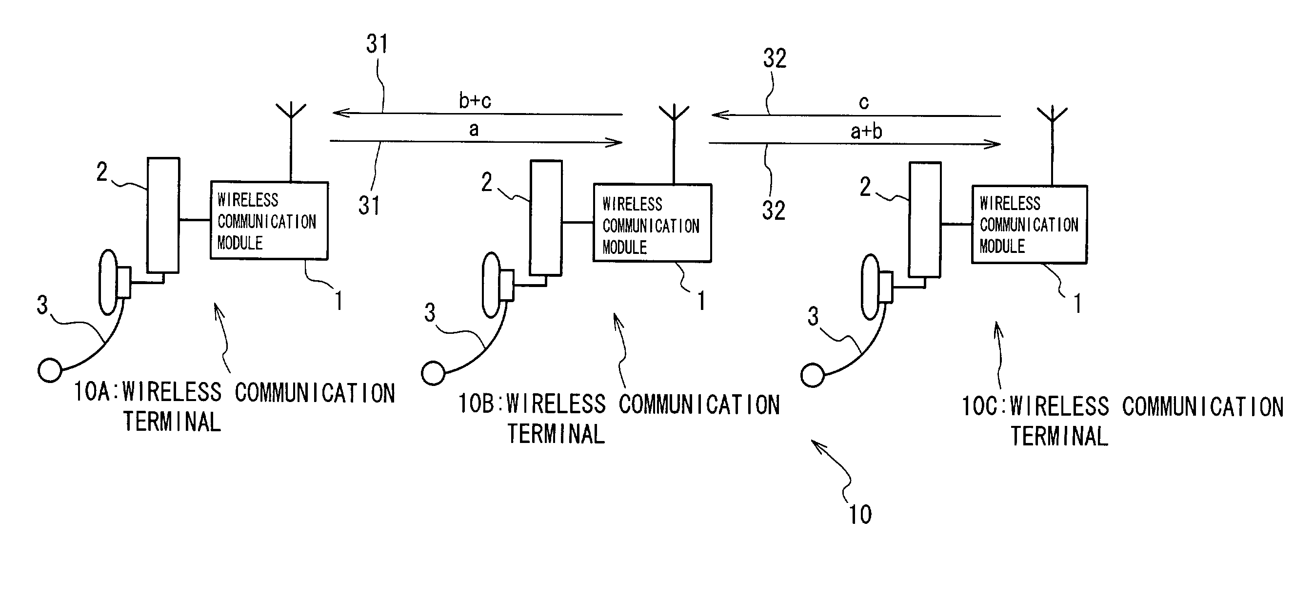
0015<figref idref="DRAWINGS">FIG. 1</figref> is a diagram illustrating a wireless communication system in which a wireless LAN (Local Area Network) is formed by wireless communication terminals according to a first embodiment of the present invention, which terminals are connected;
0016<figref idref="DRAWINGS">FIGS. 2 through 4</figref> are block diagrams, each schematically showing a style of a conversation performed over the wireless LAN;
0017<figref idref="DRAWINGS">FIG. 5</figref> is a block diagram schematically showing the individual wireless communication terminal according to the first embodiment;
0018<figref idref="DRAWINGS">FIG. 6</figref> is a block diagram schematically showing transmitting/outputting-signal mixing patterns used in the individual wireless communication terminal for a conversation;
0019<figref idref="DRAWINGS">FIG. 7</figref> is a flow diagram illustrating a succession of procedural steps of convening a voice conference performed over the wireless LAN;
0020<figref idref="DRAWINGS">FIG. 8</figref> is a diagram showing conference setting information that is to be sent to wireless communication terminals when convening for a voice conference; and
0021<figref idref="DRAWINGS">FIG. 9</figref> is a block diagram schematically showing a wireless communication system according to a second embodiment.
DESCRIPTION OF THE PREFERRED EMBODIMENTS
0022Various preferred embodiments of the present invention will now be described with reference to the accompanying drawings.
0023(A) Configurations of a Wireless Communication Terminal and Wireless Communication System According to the First Embodiment:
0024<figref idref="DRAWINGS">FIG. 1</figref> illustrates a wireless communication system in which a wireless LAN is formed by wireless communication terminals of the first embodiment, which terminals are connected. Wireless LAN <b>10</b> of <figref idref="DRAWINGS">FIG. 1</figref> is formed by three wireless communication terminals <b>10</b>A, <b>10</b>B and <b>10</b>C that are connected in series. Each of wireless communication terminals <b>10</b>A, <b>10</b>B and <b>10</b>C has at least two voice channels (in the illustrated embodiment channels #<b>0</b> and #<b>1</b>) and a data channel. The characteristic configuration of the wireless communication terminals realizes a triangular conversation (voice conference) in various predetermined styles.
0025Each of wireless communication terminals (hereinafter also simply called “terminals”) <b>10</b><i>a</i>, <b>10</b><i>b </i>and <b>10</b><i>c </i>comprises wireless communication module <b>1</b>, voice signal I/O unit <b>3</b> and mixing unit <b>2</b>, which is a feature of the present invention.
0026Wireless communication module (wireless communication unit) <b>1</b> is serially connected to terminals in order to form wireless LAN <b>10</b> via at least one voice channel and a data channel in order to perform wireless communication utilizing Bluetooth™ wireless technology or the like, and also serves as a repeater to transfer a voice signal and a data signal, which are received from one terminal in wireless LAN <b>10</b>, to another terminal.
0027Namely, wireless communication modules <b>1</b> of each terminal performs transmit and receive voice signals and data signals through the voice channels and the data channels, respectively, whereupon wireless communication terminals <b>10</b>A, <b>10</b>B and <b>10</b>C serially connected realize wireless LAN <b>10</b>. Each of wireless communication terminals <b>10</b>A, <b>10</b>B and <b>10</b>C sets the two voice channels and the data channels using frequency hopping patterns at the bandwidth of 2.4 GHz, which channels are used to receive/transmit signals having radio frequency in wireless communication module <b>1</b>.
0028Mixing unit <b>2</b> mixes voice signals, which are received from other terminals in wireless LAN <b>10</b>, into a voice signal that is to be output from voice signal I/O unit <b>3</b> as described below, and also generates voice signals to be transmitted to another terminal via wireless communication module <b>1</b> by mixing such received voice signals with voice signals input from voice signal I/O unit <b>3</b>. The specific configuration of mixing unit <b>2</b> appears in <figref idref="DRAWINGS">FIG. 5</figref>.
0029Voice signal I/O unit <b>3</b> inputs and outputs voice signals so that a user can talk with another user of another terminal in wireless LAN <b>10</b>. Voice signal I/O unit <b>3</b>, as shown in block diagram <figref idref="DRAWINGS">FIG. 5</figref>, includes signal output section <b>302</b> to reproduce the voice signal generated in mixing unit <b>2</b> mixing received signals through a non-illustrated speaker or the like, and signal input section <b>301</b> to generate an electric voice signal from voice input through a non-illustrated microphone or the like and then output the generated voice signal to mixing unit <b>2</b>.
0030In wireless LAN <b>10</b> formed by such terminals, when a particular communication mode (later described) allows terminal <b>10</b>C to receive voice signals inputted at terminals <b>10</b>A and <b>10</b>B, respectively, first of all terminal <b>10</b>A transmits voice signal a, which has been inputted from the user (hereinafter also called operator) of terminal <b>10</b>A, to terminal <b>10</b>B via mixing unit <b>2</b> and wireless communication module <b>1</b>. Upon receipt of voice signal a, mixing unit <b>2</b> of terminal <b>10</b>B mixes voice signal a with voice signal b input from the operator of terminal <b>10</b>B in order to create a mixed voice signal (a+b), which is transmitted to terminal <b>10</b>C from wireless communication module <b>1</b> of terminal <b>10</b>B.
0031At that time, assuming that terminal <b>10</b>A is allowed to receive voice signals from terminals <b>10</b>B and <b>10</b>C in the communication mode, terminal <b>10</b>C transmits voice signal c, which has been input from the operator of terminal <b>10</b>C, to terminal <b>10</b>B via mixing unit <b>2</b> and wireless communication module <b>1</b> of terminal <b>10</b>C. Upon receipt of voice signal c, mixing unit <b>2</b> of terminal <b>10</b>B mixes voice signal a with voice signal b input from the operator of terminal <b>10</b>B in order to create a mixed voice signal (b+c), which is transmitted to terminal <b>10</b>A from wireless communication module <b>1</b> of terminal <b>10</b>B.
0032When a triangular conversation is performed in such a communication mode, terminal <b>10</b>A outputs voice signal (b+c) input from the operators of terminals <b>10</b>B and <b>10</b>C to the operator, terminal <b>10</b>B outputs voice signal (a+c) from terminals <b>10</b>A and <b>10</b>C to the operator, and terminal <b>10</b>C outputs voice signal (a+b) from terminals <b>10</b>A and <b>10</b>B to the operator.
0033In the present embodiment, the configuration of each of terminals <b>10</b>A, <b>10</b>B and <b>10</b>C enables a triangular conversation in various communication modes (i.e., receiving and transmitting of voice signals are set for each of the individual terminals). As a result, terminals <b>10</b>A, <b>10</b>B and <b>10</b>C perform a triangular conversation (a voice conference) in various styles other than mutual communication as in the above example.
0034(B) Various Styles of a Triangular Conversation in the Wireless Communication System:
0035Various styles of a voice conference performed in wireless LAN <b>10</b> will now be described with reference to <figref idref="DRAWINGS">FIGS. 2 through 4</figref>. <figref idref="DRAWINGS">FIGS. 2 through 4</figref> respectively show an example of a voice conference performed over the wireless LAN <b>10</b>, focusing on voice signals received/transmitted terminals <b>10</b>A, <b>10</b>B and <b>10</b>C through the voice channels.
0036Mixing units <b>2</b> of each of terminals <b>10</b>A, <b>10</b>B and <b>10</b>C, which overall form wireless LAN <b>10</b>, enables various styles of a voice conference as shown in <figref idref="DRAWINGS">FIGS. 2 through 4</figref>.
0037As shown in <figref idref="DRAWINGS">FIGS. 2 through 4</figref>, voice signal I/O units <b>3</b> of terminals <b>10</b>A, <b>10</b>B and <b>10</b>C have voice signal I/O units <b>3</b> including signal input sections <b>301</b>A, <b>301</b>B and <b>301</b>C, and signal output sections <b>302</b>A, <b>302</b>B and <b>302</b>C, respectively. Terminal <b>10</b>B is connected to terminal <b>10</b>A through the first voice channel <b>31</b> and to terminal <b>10</b>C through second voice channel <b>32</b>. Likewise <figref idref="DRAWINGS">FIG. 1</figref>, voice signals inputted from operators of terminals <b>10</b>A, <b>10</b>B and <b>10</b>C are respectively indicated by voice signals a, b, and c.
0038(B-1) First Example:
0039In a first example shown in <figref idref="DRAWINGS">FIG. 2</figref>, terminal <b>10</b>A receives voice signal (b+c), which has been created by mixing voice signal b of terminal <b>10</b>B with voice signal c of terminal <b>10</b>C, at wireless communication module <b>1</b> through first voice channel <b>31</b> and outputs to signal output section <b>302</b>A. At that time, terminal <b>10</b>A transmits voice signal a, which is input from signal input section <b>301</b>A, to terminal <b>10</b>B through first voice channel <b>31</b>.
0040In the similar manner, terminal <b>10</b>B receives voice signal (a+c), which has been created by mixing voice signal a received from terminal <b>10</b>A through first voice channel <b>31</b> with voice signal c received from terminal <b>10</b>C through second voice channel <b>32</b>, and outputs the mixed voice signal (a+c) to signal output section <b>302</b>B. Terminal <b>10</b>B also transmits voice signal (a+b), which has been created by mixing voice signal a with voice signal b input from signal input section <b>301</b>B, to terminal <b>10</b>C through second voice channel <b>32</b>, and transmits voice signal (b+c), which has been generated by mixing voice signal c with voice signal b, to terminal <b>10</b>A through first voice channel <b>31</b>.
0041Further, terminal <b>10</b>C receives voice signal (a+b) created by mixing voice signals inputted in terminals <b>10</b>A and <b>10</b>B, at wireless communication module <b>1</b> through second voice channel <b>32</b> and outputs the received voice signal (a+b) to signal output section <b>302</b>C. At the same time, terminal <b>10</b>C transmits voice signal c input from signal input section <b>301</b>C to terminal <b>10</b>B through second voice channel <b>32</b>.
0042In the communication style described above, operators of terminals <b>10</b>A, <b>10</b>B and <b>10</b>C carry out a mutual triangular conversation (transmitting/receiving voice signals) in the first example of <figref idref="DRAWINGS">FIG. 2</figref>. Any one operator receives voices of the other two operators and transmits his/her voice to the other two. In relation to the mechanism, terminal <b>10</b>A enables reception of voice signals inputted to terminals <b>10</b>B and <b>10</b>C; terminal <b>10</b>B enables reception of voice signals inputted to terminals <b>10</b>A and <b>10</b>C; and terminal <b>10</b>C enables reception of voice signals inputted to terminals <b>10</b>A and <b>10</b>B whereupon such a mutual triangular conversation can be realized.
0043In <figref idref="DRAWINGS">FIG. 2</figref>, reference number <b>41</b> indicates a received voice signal mixing section (processor) for mixing voice signals a and c to create a mixed signal to be outputted to voice signal I/O unit <b>3</b>, in which the mixed signal is outputted to the operator; reference number <b>42</b> indicates an input voice signal mixing section for mixing voice signal b input by signal input section <b>301</b>B with voice signal c received from terminal <b>10</b>C thereby creating voice signal (b+c) to be transmitted to terminal <b>10</b>A through first voice channel <b>31</b>; and reference number <b>43</b> indicates input voice signal mixing section to mix voice signal b with voice signal a received from terminal <b>10</b>A thereby creating voice signal (a+b) to be transmitted to terminal <b>10</b>C through second voice channel <b>32</b>.
0044(B-2) Second Example:
0045In the second example shown in <figref idref="DRAWINGS">FIG. 3</figref>, voice-signal communication between terminals <b>10</b>A and <b>10</b>B is substantially identical to that of the first example, however voice-signal communication in relation to terminal <b>10</b>C is different from that of the first example. Specifically, terminal <b>10</b>C receives voice signal b from terminal <b>10</b>B through second voice channel <b>32</b> to output voice signal b to the operator from signal output section <b>302</b>C, and transmits voice signal c input from signal input section <b>301</b>C to terminal <b>10</b>B through second voice channel <b>32</b>.
0046Namely, the communication style of the second example of <figref idref="DRAWINGS">FIG. 3</figref>, voice-signal communication is performed between terminals <b>10</b>A and <b>10</b>B, and between terminals <b>10</b>B and <b>10</b>C. In addition, terminal <b>10</b>A is allowed to receive voice input from the operator of terminal <b>10</b>C; however terminal <b>10</b>C is not allowed to receive voice input by the operator of terminal <b>10</b>A.
0047In <figref idref="DRAWINGS">FIG. 3</figref>, reference number <b>41</b> indicates a received voice signal mixing section (processor) for mixing voice signals a and c to create a mixed signal to be outputted to voice signal I/O unit <b>3</b>, in which the mixed signal is outputted to the operator; and reference number <b>42</b> indicates an input voice signal mixing section for mixing voice signal b input through signal input section <b>301</b>B with voice signal c received from terminal <b>10</b>C thereby creating voice signal (b+c) to be transmitted to terminal <b>10</b>A through first voice channel <b>31</b>. Input voice signal mixing section <b>43</b> of the first example can be omitted in the illustrated example.
0048(B-3) Third Example:
0049In the third example shown in <figref idref="DRAWINGS">FIG. 4</figref>, terminal <b>10</b>A receives voice signal c, which has been input at terminal <b>10</b>C, through first voice channel <b>31</b> at wireless communication module <b>1</b> and outputs voice signal c to signal output section <b>302</b>A. Terminal <b>10</b>A also transmits voice signal a, which is input from signal input section <b>301</b>A, to terminal <b>10</b>B through first voice channel <b>31</b>.
0050Terminal <b>10</b>C receives voice signal a, which has been passed through terminal <b>10</b>B and second voice channel <b>32</b> at wireless communication module <b>1</b>, and further outputs voice signal a to signal output section <b>302</b>C. Terminal <b>10</b>C transmits voice signal c, which is input from signal input section <b>301</b>C, to terminal <b>10</b>B through second voice channel <b>32</b>. Voice signal c is received by terminal <b>10</b>B but is not output from signal output section <b>302</b>B to the operator of terminal <b>10</b>B.
0051In the triangular conversation shown in <figref idref="DRAWINGS">FIG. 4</figref>, terminal <b>10</b>B serves to function as a repeater that repeats voice-signal communication between terminals <b>10</b>A and <b>10</b>C. At that time, setting directs terminal <b>10</b>B not to output voice signals from terminals <b>10</b>A and <b>10</b>C, or not to transmit voice signals input from signal input section <b>301</b>B to terminals <b>10</b>A and <b>10</b>C.
0052(C) Description of the Wireless Communication Terminal:
0053The detailed configuration of wireless communication terminals <b>10</b>A, <b>10</b>B and <b>10</b>C is described with reference to <figref idref="DRAWINGS">FIGS. 5 and 6</figref>.
0054For example, wireless communication module <b>1</b> comprises RF (Radio Frequency) <b>101</b> to transmit and receive radio signals between other terminals in wireless LAN <b>10</b>, baseband signal section <b>102</b>, host controller interface <b>103</b> and voice signal section <b>104</b>, as shown in <figref idref="DRAWINGS">FIG. 5</figref>.
0055Baseband signal section (baseband layer) <b>102</b> performs a well-known baseband signal process conforming to Bluetooth™ on radio signals received in RF<b>101</b>, and then outputs a data signal to host controller interface <b>103</b> and a voice signal to voice signal section (voice layer) <b>104</b>. On the other hand, baseband signal section <b>102</b> performs a well-known baseband signal process on a data signal from host controller interface <b>103</b>, which signal is transmitted from the terminal through the data channel, and a voice signal from voice signal section <b>104</b>, which signals are to be transmitted from the terminal through the voice channel (0 or 1 channel). Data and voice signal processed by baseband signal section <b>102</b> are transmitted in the form of radio signals to another terminal through RF <b>101</b> and each corresponding channel.
0056Mixing unit <b>2</b> comprises setting controller <b>201</b>, channel converter <b>202</b>, first and second switch setting sections <b>203</b> and <b>204</b>, first and second processors <b>205</b> and <b>206</b>, received voice signal mixer <b>207</b>, memory <b>208</b> and input voice signal splitter <b>209</b>. Voice signal I/O unit <b>3</b> comprises signal output section <b>302</b> to output a voice signal, as a consequence of mixing by mixing unit <b>2</b> over voice signals received from other terminals in wireless LAN <b>10</b>, to the operator of the terminal in question and signal input section <b>301</b> to receive voice from the operator and output the voice to mixing unit <b>2</b> in the form of a voice signal.
0057Setting controller <b>201</b> receives and transmits data signals on the data channel with host controller interface <b>103</b> and controls first and second switch setting sections <b>203</b> and <b>204</b> to set a communication mode to be performed in first and second processors <b>205</b> and <b>206</b> on the basis of setting information retained in memory <b>208</b>. Setting controller <b>201</b> also functions as notification section <b>201</b><i>a </i>and setting changer <b>201</b><i>b. </i>
0058Notification section <b>201</b><i>a </i>notifies setting information for first and second switch setting sections <b>203</b> and <b>204</b> of each of terminals <b>10</b>A, <b>10</b>B and <b>10</b>C, which are wirelessly connected in series to form wireless LAN <b>10</b>, of the corresponding terminal through the data channels. Setting changer <b>201</b><i>b </i>changes a communication mode that is controlled by settings for first and second switch setting sections <b>203</b> and <b>204</b> based on setting information notified by another terminal in wireless LAN <b>10</b>.
0059For the purpose of the triangular conversations (voice conferences) as shown in <figref idref="DRAWINGS">FIGS. 2</figref>, <b>3</b> and <b>4</b>, each of first and second switch setting sections <b>203</b> and <b>204</b> is controlled by setting controller <b>201</b> so as to control a switching operation performed in each of first and second processors <b>205</b> and <b>206</b>.
0060In other words, setting controller <b>201</b> and first and second switch setting sections <b>203</b> and <b>204</b> overall serves to function as a controlling section that controls first and second processors <b>205</b> and <b>206</b> based on setting information retained in memory <b>208</b> in order to execute a triangular communication in a desired communication mode.
0061Channel converter <b>202</b> interfaces with wireless communication module <b>1</b> in relation to voice signals that are to be received/transmitted through the two voice channels thereby functioning as an interface. Specifically, channel converter <b>202</b> converts voice signals which are received from first and second processors <b>205</b> and <b>206</b> (later-described) and which are to be transmitted through one of the two channels into signals suitable for processing to be performed in wireless communication module <b>1</b> and outputting the converted signals to voice signal section <b>104</b> of wireless communication module <b>1</b>. In addition, channel converter <b>202</b> also converts voice signals output from voice signal section <b>104</b> into signals suitable for processing to be performed in first and second processors <b>205</b> and <b>206</b>.
0062Input voice signal splitter (branch section) <b>209</b> splits a voice signal input at signal input section <b>301</b> for two channels through which the split voice signals identical with the input voice signal flow whereupon each of first and second processors <b>205</b> and <b>206</b> receive one of the split signals respectively.
0063First processor <b>205</b> is in the form of an equivalent circuit including switches <b>11</b>, <b>12</b>, <b>13</b> and <b>14</b> and mixer <b>15</b>. Second processor <b>206</b>, identical in configuration to first processor <b>205</b>, is in the form of an equivalent circuit including switches <b>21</b>, <b>22</b>, <b>23</b> and <b>24</b> and mixer <b>25</b>.
0064First and second switch setting sections <b>203</b> and <b>204</b> set on/off-switching for each of switches <b>11</b> through <b>14</b> and <b>21</b> through <b>24</b>, respectively, so that a triangular conversation is performed among terminals <b>10</b>A, <b>10</b>B and <b>10</b>C in various communication modes exemplified by <figref idref="DRAWINGS">FIGS. 2</figref>, <b>3</b> and <b>4</b>.
0065In detail, switches <b>11</b> through <b>14</b> and mixer <b>15</b> serve to function as first mixing section <b>205</b><i>a </i>to create a mixed signal that is to be transmitted to another terminal through second voice channel <b>32</b>, one from the two voice channels. Switches <b>11</b> and <b>12</b> and mixer <b>15</b> also serve to function as first switching section <b>205</b><i>b </i>performing a switching operation between outputting and not outputting a voice signal that has been received through first voice channel <b>31</b>, one from the two voice channels, to voice signal I/O unit <b>3</b>, which outputs a voice signal for the operator.
0066In the same manner, switches <b>21</b> through <b>24</b> and mixer <b>25</b> serve to function as second mixing section <b>206</b><i>a </i>to create a mixed signal that is to be transmitted to another terminal through first voice channel <b>31</b>. Switches <b>21</b> and <b>22</b> also serve to function as second switching section <b>206</b><i>b </i>performing a switching operation between outputting and not outputting a voice signal that has been received through second voice channel <b>32</b> to voice signal I/O unit <b>3</b>.
0067As a result, first and second processors <b>205</b> and <b>206</b> function as a voice-signal processor to mix a voice signal, received through one of the two voice channels of channel converter <b>202</b>, and a voice signal split by input voice signal splitter <b>209</b> to create a mixed signal to be transmitted to a destination terminal in wireless LAN <b>10</b> through a corresponding voice channel, and to split each of the voice signals received from other terminals through corresponding channels to output the split signal for the operator.
0068Received voice signal mixer <b>207</b> mixes voice signals which have been received through the two channels and which have been output from first and second processors <b>205</b> and <b>206</b> and then outputs the mixed signal to signal output section <b>302</b> of voice signal I/O unit <b>3</b>.
0069Memory <b>208</b> previously retains setting information used for setting for mixing operations performed in first and second processors <b>205</b> and <b>206</b> in relation to mixed signals to be output to the operator or to other terminals. The setting information retained in memory <b>208</b>, as shown in <figref idref="DRAWINGS">FIG. 6</figref>, takes the form of data for on/off switching each of switches <b>11</b> through <b>14</b> and <b>21</b> through <b>24</b> of first and second processors <b>205</b> and <b>206</b> in order to perform a triangular conversation in accordance with each of various communication modes.
0070Namely, memory <b>208</b> comprises transmitting-signal mixing pattern memory <b>208</b>-<b>1</b> for a mixing operation to create second mixed signals, each to be transmitted to another terminal in wireless LAN <b>10</b>, and outputting-signal mixing pattern memory <b>208</b>-<b>2</b> for a mixing operation to create a first mixed signal to be output to voice signal I/O unit <b>3</b> for the operator so that setting information for first and second mixed signals are retained in separated forms, as shown in <figref idref="DRAWINGS">FIG. 6</figref>.
0071Transmitting-signal mixing pattern memory <b>208</b>-<b>1</b> and outputting-signal mixing pattern memory <b>208</b>-<b>2</b> respectively retain transmitting-signal mixing patterns and outputting-signal mixing patterns to create first and second mixed signals as shown in <figref idref="DRAWINGS">FIG. 6</figref>, focusing on channels through which the first and second mixed signals are transmitted or received in the same manner as <figref idref="DRAWINGS">FIGS. 2</figref>, <b>3</b> and <b>4</b>.
0072In other words, transmitting-signal mixing pattern memory <b>208</b>-<b>1</b> and outputting-signal mixing pattern memory <b>208</b>-<b>2</b> respectively retains information of on/off switching of each switch in first and second processors <b>205</b> and <b>206</b> in accordance with each mixing pattern.
0073Specifically, transmitting-signal mixing pattern memory <b>208</b>-<b>1</b> retains seven mixing patterns <b>208</b>A through <b>208</b>G, each including on/off-switching settings for switches <b>11</b> through <b>14</b> and <b>21</b> through <b>24</b>; and outputting-signal mixing pattern memory <b>208</b>-<b>2</b> retains seven mixing patterns <b>208</b>H through <b>208</b>N, each including on/off-switching settings for switches <b>11</b> through <b>14</b> and <b>21</b> through <b>24</b>.
0074When mixing pattern <b>208</b>A retained in transmitting-signal mixing pattern memory <b>208</b>-<b>1</b> is selected as the transmitting-signal mixing pattern in a terminal, input voice signal mixing section <b>42</b> mixes a voice signal received through second voice channel <b>32</b> with a voice signal input from signal input section <b>301</b> of the terminal in question to create a second voice signal to be transmitted through first voice channel <b>31</b>, and input voice signal mixing section <b>43</b> mixes a voice signal received through first voice channel <b>31</b> with the input voice signal to create a second mixed signal to be transmitted through second voice channel <b>32</b>.
0075At that time, on/off-switching settings corresponding to mixing pattern <b>208</b>A retained in transmitting-signal mixing pattern memory <b>208</b>-<b>1</b> put switches <b>21</b>, <b>23</b> and <b>24</b> of second processor <b>206</b> of <figref idref="DRAWINGS">FIG. 5</figref> into the “on” state and also put switches <b>11</b>, <b>13</b> and <b>14</b> of first processor <b>205</b> into the “on” state (by bit information of “1” or the like). Whereupon mixers <b>15</b> and <b>25</b> serve to function as input voice signal mixing sections <b>42</b> and <b>43</b> respectively when mixing pattern <b>208</b>A is selected.
0076Mixing pattern <b>208</b>B causes input voice signal mixing section <b>43</b> to mix a voice signal received through first voice channel <b>31</b> with a voice signal input in signal input section <b>301</b> of the terminal in question to create a second mixed signal that is to be transmitted through second voice channel <b>32</b>.
0077In this case, on/off-switching setting corresponding to mixing pattern <b>208</b>B retains information to put at least switches <b>23</b> and <b>24</b> into the “off” state (by bit information of “0” or the like”) and switches <b>11</b>, <b>13</b> and <b>14</b> into the “on” state (by bit information of “1” of the like). Mixer <b>15</b> therefore serves to function as input voice signal mixing section <b>43</b> when mixing pattern <b>208</b>B is selected.
0078Conversely, mixing pattern <b>208</b>C causes input voice signal mixing section <b>42</b> to mix a voice signal received through second voice channel <b>32</b> with a voice signal input in signal input section <b>301</b> of the terminal in question to create a second mixed signal that is to be transmitted through first voice channel <b>31</b>.
0079At that time, on/off-switching setting corresponding to mixing pattern <b>208</b>C retains information to put switches <b>21</b>, <b>23</b> and <b>24</b> into the “on” state and at least switches <b>13</b> and <b>14</b> into the “off” state whereupon mixer <b>25</b> serves to function as input voice signal mixing section <b>42</b> during execution of a mixing operation in mixing pattern <b>208</b>C.
0080Further, mixing pattern <b>208</b>D transmits only a voice signal input from signal input section <b>301</b> of the terminal in question through second voice channel <b>32</b>. On/off-switching setting for mixing pattern <b>208</b>D causes switch <b>14</b> to become “on” and at least switches <b>13</b>, <b>23</b> and <b>24</b> to become “off”.
0081Still further, mixing pattern <b>208</b>E transmits only a voice signal input from signal input section <b>301</b> of the terminal in question through first voice channel <b>31</b>. On/off-switching setting for mixing pattern <b>208</b>E causes switch <b>24</b> to become “on” and at least switches <b>13</b>, <b>14</b> and <b>23</b> to become “off”.
0082Mixing pattern <b>208</b>F causes input voice signal mixing section <b>42</b> to mix a voice signal received through second voice channel <b>32</b> with a voice signal input by signal input section <b>301</b> of the terminal in question to create a second mixed signal that is to be transmitted through first voice channel <b>31</b>, and at the same time create a second mixed signal which is identical to the input voice signal and which is to be transmitted through second voice channel <b>32</b>.
0083In this case, on/off-switching setting for mixing pattern <b>208</b>F causes switches <b>21</b>, <b>23</b> and <b>24</b> of second processor <b>206</b> to become “on”, switch <b>14</b> of first processor <b>205</b> to become “on” and at least switch <b>13</b> of first processor <b>205</b> to become “off”. When mixing pattern <b>208</b>F is selected, mixer <b>25</b> functions as input voice signal mixing section <b>42</b>.
0084Mixing pattern <b>208</b>G transfers a voice signal received through second voice channel <b>32</b> through first voice channel <b>31</b> whereupon the terminal in question serves to function as a repeater. On/off-switching setting for mixing pattern <b>208</b>G causes at least switches <b>21</b> and <b>23</b> to become “on” and at least switches <b>13</b>, <b>14</b> and <b>24</b> to become “off”.
0085Mixing pattern <b>208</b>H retained in outputting-signal mixing pattern memory <b>208</b>-<b>2</b> causes received voice signal mixing section <b>41</b> to mix voice signals received through first and second voice channels <b>31</b> and <b>32</b> in order to create a first mixed signal that is to be output to voice signal I/O unit <b>3</b>, which outputs the first mixed signal to the operator of the terminal in question. Further, mixing pattern <b>208</b>H also causes the terminal to transfer a voice signal received through first voice channel <b>31</b> through second voice channel <b>32</b>, and transfer a voice signal received through second voice channel <b>32</b> through first voice channel <b>31</b>.
0086On/off-switching setting for mixing pattern <b>208</b>H retains information to causes switches <b>21</b>, <b>22</b> and <b>23</b> of second processor <b>206</b> and switches <b>11</b>, <b>12</b> and <b>13</b> of first processor <b>205</b>, which are shown in <figref idref="DRAWINGS">FIG. 5</figref>, to become “on” whereupon received voice signal mixer <b>207</b> serves to function as received voice signal mixing section <b>41</b> when mixing pattern <b>208</b>H is selected.
0087Mixing pattern <b>208</b>I causes only a voice signal received through second voice channel <b>32</b> to be output from voice signal I/O unit <b>3</b> to the operator and further transfers a voice signal received through second voice channel <b>32</b> through first voice channel <b>31</b>. On/off-switching setting for mixing pattern <b>208</b>I causes switches <b>21</b>, <b>22</b> and <b>23</b> to become “on” and causes at least switch <b>12</b> to become “off”.
0088Further, when mixing pattern <b>208</b>J is selected, only a voice signal received through first voice channel <b>31</b> is output to voice signal I/O unit <b>3</b> for the operator and is transferred through second voice channel <b>32</b>. On/off switching corresponding to mixing pattern <b>208</b>J causes switches <b>11</b>, <b>12</b> and <b>13</b> to become “on” and at least switch <b>22</b> to become “off”.
0089Mixing pattern <b>208</b>K causes only a voice signal received through second voice channel <b>32</b> to be output to voice signal I/O unit <b>3</b> for the operator. On/off-switching setting for mixing pattern <b>208</b>K causes switches <b>21</b> and <b>22</b> to become “on” and at least switches <b>12</b> and <b>23</b> to become “off”.
0090Still further, mixing pattern <b>208</b>L outputs only a voice signal received through first voice channel <b>31</b> to voice signal I/O unit <b>3</b> for the operator. On/off switching setting corresponding to mixing pattern <b>208</b>L causes switches <b>11</b> and <b>12</b> of first processor <b>205</b> of <figref idref="DRAWINGS">FIG. 5</figref> to become “on” and at least switches <b>13</b> and <b>22</b> to become “off”.
0091When mixing pattern <b>208</b>M is selected, received voice signal mixing section <b>41</b> mixes two voice signals received through first and second voice channels <b>31</b> and <b>32</b>, respectively, in order to create a first mixed signal to be output to voice signal I/O unit <b>3</b>, which further outputs the first mixed signal to the operator, and the voice signal received through second voice channel <b>32</b> is transferred through first voice channel <b>31</b>.
0092At that time, on/off-switching setting for mixing pattern <b>208</b>M causes switches <b>11</b>, <b>12</b>, <b>21</b>, <b>22</b> and <b>23</b> shown in <figref idref="DRAWINGS">FIG. 5</figref> to become “on” and switch <b>13</b> to become “off”. Received voice signal mixer <b>207</b> therefore functions as received voice signal mixing section <b>41</b> when mixing pattern <b>208</b>H is selected as an outputting-signal mixing pattern.
0093When mixing pattern <b>208</b>N is selected, a voice signal received through first voice channel <b>31</b> is transferred through second voice channel <b>32</b>. On/off switching setting for mixing pattern <b>208</b>N causes switches <b>11</b> and <b>13</b> to become “on” and at least switches <b>12</b> and <b>22</b> to become “off”.
0094When a triangular conversation shown in <figref idref="DRAWINGS">FIG. 2</figref> is performed, switches <b>11</b> through <b>14</b> and <b>21</b> through <b>24</b> of first and second processors <b>205</b> and <b>206</b> of terminal <b>10</b>A are controlled by first and second switch setting sections <b>203</b> and <b>204</b> in accordance with on/off switching settings corresponding to mixing patterns <b>208</b>D and <b>208</b>K. In the same manner, switches <b>11</b> through <b>14</b> and <b>21</b> through <b>24</b> of terminal <b>10</b>B are controlled in accordance with mixing patterns <b>208</b>A and <b>208</b>H; and switches <b>11</b> through <b>14</b> and <b>21</b> through <b>24</b> in terminal <b>10</b>C are controlled in accordance with mixing patterns <b>208</b>E and <b>208</b>L.
0095Further, when a triangular conversation shown in <figref idref="DRAWINGS">FIG. 3</figref> is performed, switches <b>11</b> through <b>14</b> and <b>21</b> through <b>24</b> of first and second processors <b>205</b> and <b>206</b> of terminal <b>10</b>A are controlled by first and second switch setting sections <b>203</b> and <b>204</b> in accordance with on/off switching settings corresponding to mixing patterns <b>208</b>D and <b>208</b>K. In the same manner, switches <b>11</b> through <b>14</b> and <b>21</b> through <b>24</b> of terminal <b>10</b>B are controlled in accordance with mixing patterns <b>208</b>F and <b>208</b>M; and switches <b>11</b> through <b>14</b> and <b>21</b> through <b>24</b> in terminal <b>10</b>C are controlled in accordance with mixing patterns <b>208</b>E and <b>208</b>L.
0096Still further, when a triangular conversation shown in <figref idref="DRAWINGS">FIG. 4</figref> is performed, switches <b>11</b> through <b>14</b> and <b>21</b> through <b>24</b> of first and second processors <b>205</b> and <b>206</b> of terminal <b>10</b>A are controlled by first and second switch setting sections <b>203</b> and <b>204</b> in accordance with on/off-switching settings corresponding to mixing patterns <b>208</b>D and <b>208</b>K. In the same manner, switches <b>11</b> through <b>14</b> and <b>21</b> through <b>24</b> of terminal <b>10</b>B are controlled in accordance with mixing patterns <b>208</b>G and <b>208</b>N; and switches <b>11</b> through <b>14</b> and <b>21</b> through <b>24</b> in terminal <b>10</b>C are controlled in accordance with mixing patterns <b>208</b>E and <b>208</b>L.
0097Setting controller <b>201</b> and first and second switch setting sections <b>203</b> and <b>204</b>, serving as the controlling section, control signal transmitting/receiving through each voice channel in order to set an appropriate communication mode. It is therefore possible to set a communication mode for each terminal in wireless LAN <b>10</b>, in which a plurality of terminals (three terminals in the first embodiment) are wirelessly connected in series, which communication mode is one state selected from (i) receiving and transmitting voice signals, (ii) only receiving a voice signal, (iii) only transmitting a voice signal, and (iv) not receiving and not transmitting voice signals.
0098(D) Manner of Convening a Voice Conference in the First Embodiment:
0099When one terminal in wireless LAN <b>10</b> of the first embodiment notifies convening of a voice conference to other terminals in wireless LAN <b>10</b>, data communication is performed through the data channel as shown in flow diagram <figref idref="DRAWINGS">FIG. 7</figref> (steps S<b>1</b> through S<b>6</b>).
0100When one terminal (for example, terminal <b>10</b>A) convenes a voice conference, the terminal causes setting controller <b>201</b> to create conversation setting information <b>50</b> as shown in <figref idref="DRAWINGS">FIG. 8</figref> (step S<b>1</b>), and notification section <b>201</b><i>a </i>of setting controller <b>201</b> transmits the created conversation setting information <b>50</b> to other terminals in wireless LAN <b>10</b> via the data channel (step S<b>2</b>).
0101Conversation setting information <b>50</b> to be transmitted by notification section <b>201</b><i>a </i>takes the form of 72-bit access code <b>51</b>, 54-bit header <b>52</b>, and payload <b>53</b> having a variable length between 0 through 2745 bits. Payload <b>53</b> is formed by sets of terminal information <b>53</b><i>a </i>including identification (ID) of a terminal and information whether or not the terminal is invited to the voice conference, transmitting-signal (mixing) pattern identification information <b>53</b><i>b </i>and outputting-signal (mixing) pattern identification information <b>53</b><i>c </i>corresponding to a communication mode of the voice conference, each set for each terminal in wireless LAN <b>10</b>.
0102Conversation setting information <b>50</b> transmitted from the terminal that convenes the voice conference is received at RF <b>101</b> of wireless communication module <b>1</b> of each terminal that (step S<b>3</b>). After that, the received conversation setting information <b>50</b> is extracted in baseband signal section <b>102</b> and then output to setting controller <b>201</b> of mixing unit <b>2</b> through host controller interface <b>103</b>.
0103Upon receipt of conversation setting information <b>50</b>, each of the other terminals <b>10</b>B and <b>10</b>C extracts terminal information <b>53</b><i>a </i>(terminal ID and information whether or not the terminal is invited to the voice conference) and transmitting-/outputting-signal mixing pattern identification information <b>53</b><i>b </i>and <b>53</b><i>c </i>corresponding to the terminal at setting controller <b>201</b> (step S<b>3</b>).
0104If a terminal is invited, setting controller <b>201</b> of the terminal refers to memory <b>208</b> based on transmitting-/outputting-signal mixing pattern identification information <b>53</b><i>b </i>and <b>53</b><i>c, </i>which has been set for the terminal, and extracts transmitting-/outputting-signal mixing patterns in order to set a communication mode.
0105After that, when first and second switch setting sections <b>203</b> and <b>204</b> receive instructions from setting controller <b>201</b>, first and second switch setting sections <b>203</b> and <b>204</b> control first and second processors <b>205</b> and <b>206</b>, respectively, such that the terminal performs a conversation of the voice conference in the desired communication mode. If a terminal in wireless LAN <b>10</b> is not invited to the voice conference, the terminal sets itself to serve as a repeater that transfers a voice signal to be transmitted to or received by other terminals in wireless LAN <b>10</b> (hereinbefore Yes route in step S<b>4</b> to step S<b>5</b> and step S<b>6</b>).
0106Upon completion of setting for the desired communication mode in the individual terminals in wireless LAN <b>10</b>, the voice conference can be started. The settings are canceled when the voice conference is over.
0107Further, if notification section <b>201</b><i>a </i>of setting controller <b>201</b> of a terminal, which is participating in the voice conference and which is serially connected to terminals in wireless LAN <b>10</b>, notifies setting information to other terminals through the data channel even during the voice conference, the other terminals, which have received the setting information, cause setting changer <b>201</b><i>b </i>therein to change the communication mode in accordance with the received setting information.
0108Transmitting-/outputting-signal mixing pattern identification information <b>53</b><i>b </i>and <b>53</b><i>c </i>included in conversation setting information <b>50</b> may be in the form of transmitting/outputting-signal mixing patterns.
0109Special authority may be granted to a terminal that is allowed to convene a voice conference and/or to change a communication mode during a voice conference. Namely, it is possible to prohibit a terminal without such authority from convening a voice conference or changing a communication mode. Alternatively, it is possible to grant authority to change and set a voice conference in one or more particular communication modes.
0110(E) Result of the Invention:
0111As described above, in a wireless communication terminal of the first embodiment, mixing unit <b>2</b> performs mixing operations in order to create a first mixed signal to be output from voice signal I/O unit <b>3</b> for the operator and a second mixed signal to be transmitted to another terminal through wireless communication module <b>1</b> on the basis of a communication mode predetermined among terminals serially connected. As a result, since the present invention enables a voice conference among wireless communication terminals without a server (center apparatus) and a dedicated repeater, the voice conference is carried out in a small and simple system, thereby reducing the cost of the system.
0112If a terminal forming wireless LAN <b>10</b> does not participate in a voice conference, the communication mode for the terminal is successfully set by making transmitting-/outputting-signal mixing patterns <b>208</b>G and <b>208</b>N (transferring patterns; <figref idref="DRAWINGS">FIG. 6</figref>). It is therefore possible to select particular terminals that are to participate in a voice conference from a number of terminals communicating via the same frequency band. Further, it is possible to set a communication mode for each of the terminals participating in a voice conference in accordance with the style of the voice conference thereby improving the advantage of such a voice conference.
0113A combination of one of transmitting-signal mixing patterns <b>208</b>A through <b>208</b>G (see <figref idref="DRAWINGS">FIG. 6</figref>) retained in transmitting-signal mixing pattern memory <b>208</b>-<b>1</b> and one of outputting-signal mixing patterns <b>208</b>H through <b>208</b>N (see <figref idref="DRAWINGS">FIG. 6</figref>) in outputting-signal mixing pattern memory <b>208</b>-<b>2</b> allows each terminal in wireless LAN <b>10</b> to perform two-directional conversation for a voice conference or the like and one-directional conversation and to function as a repeater, thereby improving service to users.
0114(F) Second Embodiment:
0115<figref idref="DRAWINGS">FIG. 9</figref> schematically shows a wireless communication system according to a second embodiment. Wireless communication system <b>60</b> of <figref idref="DRAWINGS">FIG. 9</figref> is formed by wireless networks <b>62</b>A, <b>62</b>B and <b>62</b>C, which are communicably connected via a public network (or an interchange network) <b>61</b>. Wireless networks <b>62</b>A, <b>62</b>B and <b>62</b>C respectively include wireless stations <b>62</b><i>a, </i><b>62</b><i>b </i>and <b>62</b><i>c. </i>Wireless networks <b>62</b>A, <b>62</b>B and <b>62</b>C further include wireless communication terminal <b>62</b><i>a</i>-<b>1</b>, <b>62</b><i>b</i>-<b>1</b> and <b>62</b><i>c</i>-<b>1</b>, respectively.
0116Wireless communication terminals <b>62</b><i>a</i>-<b>1</b>, <b>62</b><i>a</i>-<b>2</b> and <b>62</b><i>a</i>-<b>3</b> are serially connected conforming to Bluetooth™ wireless technology thereby forming wireless LAN <b>62</b><i>a</i>-<b>4</b> substantially identical to wireless LAN <b>10</b> of <figref idref="DRAWINGS">FIG. 1</figref>. In the same way, wireless communication terminals <b>62</b><i>b</i>-<b>1</b> and <b>62</b><i>b</i>-<b>2</b> form wireless LAN <b>62</b><i>b</i>-<b>3</b> substantially identical to wireless LAN <b>10</b> of <figref idref="DRAWINGS">FIG. 1</figref>.
0117Each of wireless communication terminals <b>62</b><i>a</i>-<b>1</b> to <b>62</b><i>a</i>-<b>3</b>, <b>62</b><i>b</i>-<b>1</b> and <b>62</b><i>b</i>-<b>2</b> that form wireless LANs <b>62</b><i>a</i>-<b>4</b> and <b>62</b><i>b</i>-<b>3</b>, includes wireless communication module <b>1</b>, mixing unit <b>2</b> and voice signal I/O unit <b>3</b> identical to the wireless communication terminal of <figref idref="DRAWINGS">FIG. 5</figref>. The presence of mixing unit <b>2</b> in each wireless communication terminal realizes the creation of a mixed voice signal to be output to voice signal I/O unit <b>3</b> and the creation of mixed signals to be transmitted to other wireless communication terminals via wireless communication module <b>1</b> therein in accordance with a communication mode.
0118Wireless communication terminal <b>62</b><i>a</i>-<b>1</b> included in wireless station <b>62</b><i>a </i>mixes voice signal (a<b>2</b>+a<b>3</b>), as the consequence of mixing voice signals input in other terminals <b>62</b><i>a</i>-<b>2</b> and <b>62</b><i>a</i>-<b>3</b> in wireless LAN <b>62</b><i>a</i>-<b>4</b>, with voice signal a<b>1</b> input in communication terminal <b>62</b><i>a</i>-<b>1</b> itself to create mixed voice signal (a<b>1</b>+a<b>2</b>+a<b>3</b>). After that, wireless communication terminal <b>62</b><i>a</i>-<b>1</b> transmits the mixed voice signal (a<b>1</b>+a<b>2</b>+a<b>3</b>) to other networks <b>62</b>B and <b>62</b>C through wireless station <b>62</b><i>a </i>and public network <b>61</b>.
0119In the same way, wireless communication terminal <b>62</b><i>b</i>-<b>1</b> included in wireless station <b>62</b><i>b </i>mixes voice signal b<b>2</b>, which has been input in the other wireless communication terminal <b>62</b><i>b</i>-<b>2</b> in wireless LAN <b>62</b><i>b</i>-<b>3</b>, with voice signal b<b>1</b> input in communication terminal <b>62</b><i>b</i>-<b>1</b> itself to create mixed voice signal (b<b>1</b>+b<b>2</b>). After that, wireless communication terminal <b>62</b><i>b</i>-<b>1</b> transmits the mixed voice signal (b<b>1</b>+b<b>2</b>) to other networks <b>62</b>A and <b>62</b>C through wireless station <b>62</b><i>a </i>and public network <b>61</b>.
0120Wireless communication terminals <b>62</b><i>a</i>-<b>1</b> to <b>62</b><i>c</i>-<b>1</b> included in wireless stations <b>62</b><i>a </i>through <b>62</b><i>c </i>can perform communication among more than two terminals by utilizing a conventional triangular conversation service known in the art.
0121Wireless communication terminal <b>62</b><i>a</i>-<b>1</b> forming wireless LAN <b>62</b><i>a</i>-<b>4</b> receives voice signal ((b<b>1</b>+b<b>2</b>)+c<b>1</b>), as the consequence of mixed voice signals (b<b>1</b>+b<b>2</b>) and c<b>1</b> transmitted respectively by wireless communication terminals <b>62</b><i>b</i>-<b>1</b> and <b>62</b><i>c</i>-<b>1</b> included in other wireless communication networks <b>62</b>B and <b>62</b>C, and then outputs the mixed voice signal ((b<b>1</b>+b<b>2</b>)+c<b>1</b>) for the operator.
0122Further, wireless communication terminal <b>62</b><i>a</i>-<b>2</b> receives voice signal (a<b>1</b>+(b<b>1</b>+b<b>2</b>)+c<b>1</b>), which is created by mixing voice signal a<b>1</b> input in wireless communication terminal <b>62</b><i>a</i>-l with the above voice signal ((b<b>1</b>+b<b>2</b>)+c<b>1</b>), and outputs the mixed signal to the operator. Wireless communication terminal <b>62</b><i>a</i>-<b>3</b> receives voice signal ((a<b>1</b>+a<b>2</b>)+(b<b>1</b>+b<b>2</b>)+c<b>1</b>), which is created by mixing voice signals which wireless communication terminal <b>62</b><i>a</i>-<b>2</b> received from wireless communication terminal <b>62</b><i>a</i>-<b>1</b> with voice signal a<b>2</b> input at the wireless communication terminal <b>62</b><i>a</i>-<b>2</b>. Then, wireless communication terminal <b>62</b><i>a</i>-<b>3</b> outputs the mixed voice signal ((a<b>1</b>+a<b>2</b>)+(b<b>1</b>+b<b>2</b>)+c<b>1</b>) to the operator.
0123Wireless communication terminal <b>62</b><i>b</i>-<b>1</b> forming wireless LAN <b>62</b><i>b</i>-<b>3</b> receives and outputs voice signal ((a<b>1</b>+a<b>2</b>+a<b>3</b>)+c<b>1</b>) transmitted from public network <b>61</b>, which signal is a result of mixing of voice signals transmitted from other wireless networks <b>62</b>A and <b>62</b>C. Wireless communication terminal <b>62</b><i>b</i>-<b>2</b> receives and outputs voice signal ((a<b>1</b>+a<b>2</b>+a<b>3</b>)+b<b>1</b>+c<b>1</b>), which is created by mixing the above-mentioned voice signal ((a<b>1</b>+a<b>2</b>+a<b>3</b>)+c<b>1</b>) with voice signal b<b>1</b> transmitted from wireless communication terminal <b>62</b><i>b</i>-<b>1</b>.
0124Further, wireless communication terminal <b>62</b><i>c</i>-<b>1</b> that is a part of wireless LAN <b>62</b><i>c </i>receives and outputs voice signal ((a<b>1</b>+a<b>2</b>+a<b>3</b>)+(b<b>1</b>+b<b>2</b>)) that is the result of mixing of voice signals transmitted from wireless communication terminals <b>62</b><i>a</i>-<b>1</b> and <b>62</b><i>b</i>-<b>1</b> respectively in wireless communication network <b>62</b>A and <b>62</b>B.
0125A voice conference can be performed in wireless communication system <b>60</b> of <figref idref="DRAWINGS">FIG. 9</figref> in the same manner as steps S<b>1</b> through S<b>6</b> shown in flow diagram <figref idref="DRAWINGS">FIG. 7</figref>. When a communication terminal convenes a voice conference to another wireless LAN mutually connected via public network <b>61</b>, conference setting information is first of all transmitted to one or more wireless communication terminals <b>61</b><i>a</i>-<b>1</b> to <b>61</b><i>c</i>-<b>1</b> in the same LAN as the communication terminal that convenes a voice conference and then is spread over the wireless communication network <b>60</b>. Conference setting information is created by incorporating data to invite other LANs to a voice conference in payload <b>53</b> of conversation setting information <b>50</b>.
0126The second embodiment therefore guarantees the same advantageous result as the first embodiment described in index (E). Additionally, a voice conference (a triangular conversation) can be performed over a number of wireless LANs whereupon it is possible to extend the advantageous function for a voice communication performed over a wireless LAN. As a result, the service to users (operators) of each wireless communication terminal is improved.
0127(G) Others:
0128Mixing unit <b>2</b> of each of terminals <b>10</b>A, <b>10</b>B and <b>10</b>C shown in <figref idref="DRAWINGS">FIG. 5</figref> may be realized by all-in-one hardware exemplified by an ASIC (Application Specific Integrated Circuit). Setting controller <b>201</b> and first and second switch setting sections <b>203</b> and <b>204</b> may be in the form of separated units or an all-in-one unit.
0129As an alternative, setting controller <b>201</b> may be realized by a processor that executes a program stored in memory <b>208</b>.
0130In the first embodiment, wireless LAN <b>10</b> includes three terminals <b>10</b>A, <b>10</b>B and <b>10</b>C connected in series. The present invention should by no means be limited to a wireless LAN having three terminals. Alternatively, four or more terminals serially connected may constitute wireless LAN <b>10</b>.
0131Each of terminals <b>10</b>A, <b>10</b>B and <b>10</b>C comprises two voice channels and a data channel in the first embodiment. The number and the kind of channels should by no means be limited to this. A terminal having three or more voice channels may be applied to the present invention by utilizing two of the voice channels.
0132Further, the present invention should by no means be limited to these foregoing embodiments, and various changes or modifications may be suggested without departing from the gist of the invention.
Contents4
10 sheets
Sheet 1 Sheet 2 Sheet 3 Sheet 4 Sheet 5 Sheet 6 Sheet 7 Sheet 8 Sheet 9 Sheet 10
Every citation, both ways
| Document | Relation | Office | Cited during |
|---|---|---|---|
| US8428634B2 | Cited by | United States of America | Search report |
| US2007097886A1 | Cited by | United States of America | Pre-grant |
| US2001018328A1 | Cites | United States of America | Search report |
| JP2001148657A | Cites | Japan | Applicant |
| US2002039885A1 | Cites | United States of America | Search report |
| US2002045461A1 | Cites | United States of America | Search report |
| US2004110469A1 | Cites | United States of America | Search report |
| US3939417A | Cites | United States of America | Search report |
| US5349694A | Cites | United States of America | Search report |
| US6141533A | Cites | United States of America | Search report |
| US6185430B1 | Cites | United States of America | Search report |
| US6404775B1 | Cites | United States of America | Search report |
| US6606482B1 | Cites | United States of America | Search report |
| US6650629B1 | Cites | United States of America | Search report |
| JPH0831907A | Cites | Japan | Applicant |
| JPS59169236A | Cites | Japan | Applicant |
5 priority claims, no other members on record
Priority claims5
| Document | Office | Kind | Date |
|---|---|---|---|
| 2002074582 | Japan | – | |
| 2002074582 | Japan | A | |
| 2002074582 | Japan | A | |
| 2002074582 | – | – | – |
| JP20020074582 | – | – | – |
29 transactions on the USPTO file
Allowed after 1 non-final rejection.
- Non-final rejections
- 1
- Final rejections
- 0
- RCEs
- 0
- Appeals
- 0
Over time
Point at a mark for the transactionTransactions
| Event | |
|---|---|
| Expire Patent | |
| Maintenance Fee Reminder Mailed | |
| Recordation of Patent Grant Mailed | |
| Patent Issue Date Used in PTA CalculationAllowed | |
| Issue Notification MailedAllowed | |
| Dispatch to FDC | |
| Application Is Considered Ready for Issue | |
| Issue Fee Payment Verified | |
| Issue Fee Payment Received | |
| Mail Notice of AllowanceAllowed | |
| Notice of Allowance Data Verification CompletedAllowed | |
| Case Docketed to Examiner in GAU | |
| Date Forwarded to Examiner | |
| Response after Non-Final Action | |
| Request for Extension of Time - Granted | |
| Mail Non-Final RejectionNon-final rejection | |
| Non-Final RejectionNon-final rejection | |
| Case Docketed to Examiner in GAU | |
| IFW TSS Processing by Tech Center Complete | |
| Case Docketed to Examiner in GAU | |
| Case Docketed to Examiner in GAU | |
| Transfer Inquiry to GAU | |
| Application Dispatched from OIPE | |
| Application Is Now Complete | |
| IFW Scan & PACR Auto Security Review | |
| Information Disclosure Statement (IDS) Filed | |
| Information Disclosure Statement (IDS) Filed | |
| Request for Foreign Priority (Priority Papers May Be Included) | |
| Initial Exam Team nn |
7 legal events, as the office reported them to INPADOC
Over the term
Point at a mark for the eventEvents
| Event | Code | |
|---|---|---|
| Lapsed due to failure to pay maintenance feeLapsedFP | FP | |
| Lapse for failure to pay maintenance feesLapsedPATENT EXPIRED FOR FAILURE TO PAY MAINTENANCE FEES (ORIGINAL EVENT CODE: EXP.)LAPS | LAPS | |
| Information on status: patent discontinuationPATENT EXPIRED DUE TO NONPAYMENT OF MAINTENANCE FEES UNDER 37 CFR 1.362STCH | STCH | |
| Fee payment procedureMAINTENANCE FEE REMINDER MAILED (ORIGINAL EVENT CODE: REM.)FEPP | FEPP | |
| Fee paymentFPAY | FPAY | |
| Fee paymentFPAY | FPAY | |
| AssignmentAS | AS |
Numbers
- Publication
- 06996411
- Publication, DOCDB
- 6996411
- Publication, EPODOC
- US6996411
- Application
- 10280984
- Application, DOCDB
- 28098402
- Application, EPODOC
- US20020280984
Titles
- English
- Wireless communication terminal
Patent term adjustment
- A delay
- +445 daysthe office missed an examination deadline
- Applicant delay
- −62 days
- Net adjustment
- 383 days
Classification
- CPC, 5
- H04M3/568
- H04M1/72513
- H04M3/56
- H04M2203/5018
- H04W88/02
- IPC, 10
- H04B7 00
- H04Q7 20
- H04B7 24
- H04L12 28
- H04M1 72513
- H04M3 56
- H04M9 00
- H04W74 08
- H04W84 12
- H04W88 02
- USPC, 3
- 455500000
- 455011100
- 455518000