Soldering machine
Abstract
This record has no abstract on file.
Term
Term ended
Expired 5 June 1940, 86.3 years ago.
- Priority and filed
- Granted
- Expired
- Today
25 claims: 25 independent, 0 dependent
- 1What is claimed is:1. In a soldering machine, the combina 40 tion of an intermittently movable carrier, an endless series of seats and retaining members arranged along said carrier for holding pairs of separate articles in contact with each other to be soldered together, said 45 seats being arranged to permit both of said articles to gravitate one above the other and to arrest the same when in alined position, and means for feeding solder intermittently to the joint between the articles of said pairs 50 after they are positioned on said seats and as they are presented by the movement of said carrier.
- 2In a soldering machine, the combination of an intermittently movable, carrier, 55 an endless series of inclined and shouldered seats and pivoted recessed retaining members arranged along said carrier for holding pairs of separate articles in contact with each other to be soldered together, said °θ seats being arranged to permit both of said articles to gravitate one above the other and to arrest the same when in alined position, and soldering means adapted to operate on said pairs of articles as they are presented 65 by the movement of said carrier.
- 3In a soldering machine, the combination of an intermittently movable carrier, an endless series of inclined and shouldered seats and retaining members arranged along said carrier for holding pairs of separate articles in contact with each other to be soldered together, said seats being arranged to permit both of said articles to gravitate one above the other and to arrest the same when in alined position, and means for feed- 75 ing solder intermittently to the joint between the articles of said pairs after they are positioned on said seats and as they are presented by the movement of said carrier. _
- 4In a soldering machine, the combina- 80 tion of an intermittently movable carrier, an endless series of seats and retaining members arranged along said carrier for holding relatively flat articles and cylindrical articles superposed thereon to be soldered 85 together in pairs, said seats being arranged to permit both of said articles to gravitate one above the other and to arrest the same when in alined position, and means for feeding solder intermittently to the joint lie- 90 tween the articles of said pairs after they are positioned on said seats and as thev are presented by the movement of said carrier.
- 5In a soldering machine, the combination of an intermittently movable carrier, 05 an endless series of seats and retaining members arranged along said carrier for holding relatively wide articles and narrower articles superposed thereon to be soldered together in pairs, said seats being arranged to permit 100 both of said articles to gravitate one above the other and to arrest the same when in alined position, and means for feeding solder intermittently to the joint between the articles of said pairs after they are posi- 705 tioned on said seats and as they are presented by the movement of said carrier. _
- 6In a soldering machine, the combination of an intermittently movable carrier rotary on an axis, an endless series of inclined liu and shouldered seats and radially recessed retaining members arranged along said carrier for holding relatively flat articles and cylindrical articles superposed thereon to be soldered together in pairs, said seats being 115 arranged to permit both of said articles to gravitate one above the other and to arrest the same when in alined position, and soldering means adapted io operate on said pairs of articles as they arc- presented bv the 120 movement of said carrier, the said seats and recesses of the.retaining members extending in horizontal directions and radially from the center of said carrier.
- 7In a soldering machine, the combina- 125 tion of an intermittently movable carrier, seats arranged along said carrier for holding caps in position for soldering, nozzle retaining members co-operating with said seats io separately hold nozzles extending ISO 1,487,804 a over and resting on said caps, said seats being arranged and inclined to permit said caps and nozzles both to gravitate, one superposed on the other, and to arrest the 6 same in alined position, and soldering means adapted to operate on said caps and nozzles so relatively positioned as they are presented by the movement of said carrier.
- 8In a soldering machine, the combina 10 tion of a horizontal intermittently rotary carrier, seats spaced around said carrier for holding caps in position for soldering, nozzle retaining members co-operating with said seats to separately hold nozzles extend18 ing over and resting on said caps, said seats being arranged and inclined to permit said caps and nozzles both to gravitate, one superposed on the other, and to arrest the same in alined position, and soldering means 20 adapted to operate on said caps and nozzles so relatively positioned as they are presented by the movement of said carrier.
- 9In a soldering machine, the combination of an intermittently movable carrier, 25 seats arranged along said carrier for holding caps in position for soldering, nozzle retaining members movable relative to and cooperating with said seats to separately hold nozzles extending over and resting on said 30 caps, said seats being arranged and inclined to permit said caps and nozzles both to gravitate, one superposed on the other, and to arrest the same in alined position, and soldering means adapted to operate on said caps 35 and nozzles so relatively positioned as they are presented by the movement of said carrier.
- 10In a soldering machine, the combination of a horizontal intermittently movable 40 carrier rotary on an axis, a series of cap seats arranged around the same having inclined cap-supporting faces and a radial cap-retaining shoulder, movable nozzle holders arranged to maintain the nozzles in 45 radial line above and resting on the retained caps, said seats being arranged and inclined to permit said caps and nozzles both to gravitate, one superposed on the other, and to arrest the same in alined position, and 50 soldering means adapted to operate on said caps ana nozzles as they are presented by the movement of said carrier.
- 11In a soldering machine, the combination of a horizontal intermittently movable 55 carrier rotary on an axis, a series of cap seats arranged around the same having inclined cap-supporting faces and a radial cap retaining shoulder, movable radially recessed nozzle holders arranged to maintain 60 the nozzles in radial line above and resting on the retained caps, said seats being arranged and inclined to permit said caps and nozzles both to gravitate, one superposed on the other, and to arrest the same m alined 55 position, and soldering means adapted to operate on said caps and nozzles as they are presented by the movement of said carrier.
- 12In a soldering machine, the combination of a horizontal intermittently movable carrier rotary on an axis, a series of cap 70 seats arranged around the same having inclined cap-supporting faces and a radial cap-retaining shoulder and a nozzle-holding abutment, movable nozzle holders arranged to maintain the nozzles in radial line above 75 and resting on the retained caps, said seats being arranged and inclined to permit said caps and nozzles both to gravitate, one superposed on the other, ana to arrest the same in alined position, and soldering means 8® adapted to operate on said caps and nozzles as they are presented by the movement of said carrier.
- 13In a soldering machine, the combination of an intermittent carrier, an endless 86 series of spaced seats on said carrier having inclined and shouldered article holding faces, said seats causing a pair of articles to gravitate relative to the carrier and to be arrested in alined position, a soldering iron 90 movable vertically and horizontally relative to articles on said seats as they are presented by the movement of the carrier, and mechanism for operating said carrier and soldering iron. 95
- 14In a soldering machine, the combination of a work-holder, soldering mechanism comprising opposing solder-feeding rolls, means for advancing and retracting one of said rolls relative to the other roll and to- 100 wards and from the place on said workholder where the soldering is performed, means for turning said roll to feed the solder and for freeing the same to roll on the solder strip when said roll is retracted, and means 105 for melting the solder after it is advanced.
- 15In a soldering machine, the combination of a work-carrier adapted to present successively articles to be soldered to a soldering mechanism, and said soldering 110 mechanism comprising opposing solder-feeding rolls, means for advancing and retracting one of said rolls relative to the other roll and towards and from the place on said carrier where the soldering is per- 115 formed, means for turning said roll to feed the solder and for freeing the same to roll on the solder strip when said roll is retracted, and means for melting the solder after it is advanced. 120
- 16In a soldering machine, the combination of a work-carrier adapted to present successively articles to be soldered to a soldering mechanism, and said soldering mechanism comprising opposing solder-feeding 125 rolls, means for advancing and retracting one of said rolls relative to the other roll and towards and from the place on said carrier where the soldering is performed, a fixed support connected with said rolls to iso 1,467,604 cause the turning of the same to feed the solder, said connection leaving the roll free to roll on the solder strip when said roll is retracted, and means for melting the solder 5 after it is advanced.
- 17In a soldering machine, the combination of an intermittently movable carrier, an endless series of article-holding means arranged along said carrier, and soldering 10 means arranged to operate on a series of articles held by said holding means, said soldering means comprising a swinging arm, rotary solder-grasping opposing rolls co-operating with said arm, one of said rolls being 16 carried by said arm and movable relative to the other roll, means for swinging said arm away from the solder supply and towards the place of soldering and then swinging said arm reversely, ana means for caus20 ing the roll which is carried by the arm to be turned in directions opposite to the directions of swinging said arm.
- 18In a soldering machine, the combination of an intermittently movable carrier, an 25 endless series of article-holding means arranged along said carrier, and soldering means arranged to operate on a series of articles held by said holding means, said soldering means comprising a swinging arm, SO a rotary solder-grasping opposing rolls cooperating with said arm, one of said rolls being carried by said arm and movable relative to the other roll, means for swinging said arm away from the solder supply ana 85 towards the place of soldering and then swinging said arm reversely, means for causing the roll which is carried by the arm to be turned in directions opposite to the directions of swinging of said arm, and means 40 for adjusting tne extent of movement of said swinging arm.
- 19In a soldering machine, the combination of an intermittently movable carrier, an endless series of article-holding means ar45 ranged along said carrier, and soldering means arranged to operate on a series of articles held by said holding means, said soldering means comprising a swinging arm, rotary solder-grasping opposing rolls co50 operating with said arm, one of said rolls being carried by said arm and movable relative to the other roll, means for swinging said arm away from the solder supply and towards the place of soldering and then 55 swinging said arm reversely, and a fixed support on the frame of the machine having means for causing the roll which is carried by the arm to be turned in directions opposite to the directions of swinging of said 60 arm.
- 20In a soldering machine, the combination of an intermittently rotatable carrier having an endless series of inclined articleholding devices, the inclination of said arti65 cle holding devices causing the separate gravitation and arrest in alined position of the articles to be united, a flux pan, a flux applying brush swingable vertically and horizontally into said pan and thence into contact with articles on said holding devices, 70 a solder feeding means, a soldering iron movable downwardly into the angle between two articles to be soldered together when they are presented by said holding devices and also movable horizontally, and mecha- 75 nism for operating said carrier and brush and soldering iron. '
- 21In a soldering machine, the combination of a horizontal intermittently rotatable carrier having a vertical axis and an endless 80 series of spaced article-holding means, means for applying flux to said articles, a soldering iron which is vertically movable and horizontally slidable to which iron the articles to be soldered are presented by said carrier, 85 a solder-feeding means for advancing the solder to the place of soldering, a horizontal shaft arranged across said carrier, and devices actuated by said shaft for operating said flux-applying means and for moving so the soldering iron vertically and horizontally and for operating said solder-feeding means.
- 22In a soldering machine, a solder-strip feeding means comprising solder grasping 05 rolls, a means for turning said rolls to advance the solder, and means for advancing and retracting one of said rolls, said feeding means being controlled by the presence or absence of an article to be soldered. 100
- 23In a soldering machine for uniting nozzles to the tops of caps, the combination of a rotary carrier having a vertical axis, a series of seats 'arranged on said carrier around said axis and extending radially 105 from the latter, said seats having means for inclosing the end of a nozzle to hold the same in horizontal position, a stop for arresting the nozzle when it has gravitated into said position, each of said seats having 110 an inclined surface on which the caps may gravitate relative to the nozzle and a stop for arresting the cap when in alinement beneath the nozzle, so that the caps and nozzles may be separately and radially supplied 115 to said seats and will respectively gravitate into the required position for union with each other, means for applying solder to said nozzles and caps, and means for rotating said carrier. 120
- 24In a soldering machine, the combination of an endless carrier rotary on an axis, means for actuating the same, an endless series of retaining devices fixed on said carrier having recesses for holding the ends of 125 articles, an endless series of seats for other articles to be soldered to the first mentioned articles, each of said seats having means for alining one of said articles with the other, and soldering means adapted to operate on 180 1,487,804 *7 the pairs of alined articles as they are presented by the movement of said carrier.
- 25In a soldering machine, the combination of an endless carrier, means for actuats ing the same, an endless series of retaining devices fixed on said carrier and having recesses for holding the ends of nozzles, an endless series of inclined seats for caps to be soldered to the nozzles, each of said seats having means for arresting the caps when io they are alined with the nozzles, and soldering means adapted to operate on the pairs of aimed articles as they are presented by the movement of said carrier. In testimony whereof we affix our signa- 15 tures. WILLIAM J. CULLEN. WALTER L. RUTKOWSKI.
Independent claims25
47 paragraphs, as filed
Application filed March 20, 1919. ferial No. 283,785.
being shown in horizontal sections and other parts being removed.
Fig. 7 is a detail sectional view enlarged, on line VII—VII of Figure 6.
Fig. 8 is a vertical section on line VIII— 60 VIII of Figure 5, with the mechanism in solder-feeding position.
Fig. 9 is a similar view with the mechanism in a retarded non-solder-feeding position. . . <sup>85</sup>
Fig. 10 is a vertical section on line X—X of Figure 4.
Fig. 11 is a front elevation of the lower part of the machine and solder supply..
Fig. 12 is an enlarged plan view of seat 70 and clamp members for positioning caps and spouts while soldering.
Fig. 13 is a front end elevation of Fig. 12.
Fig. 14 is a sectional view on line XIV— XIV of Figures 12 and 13. 75
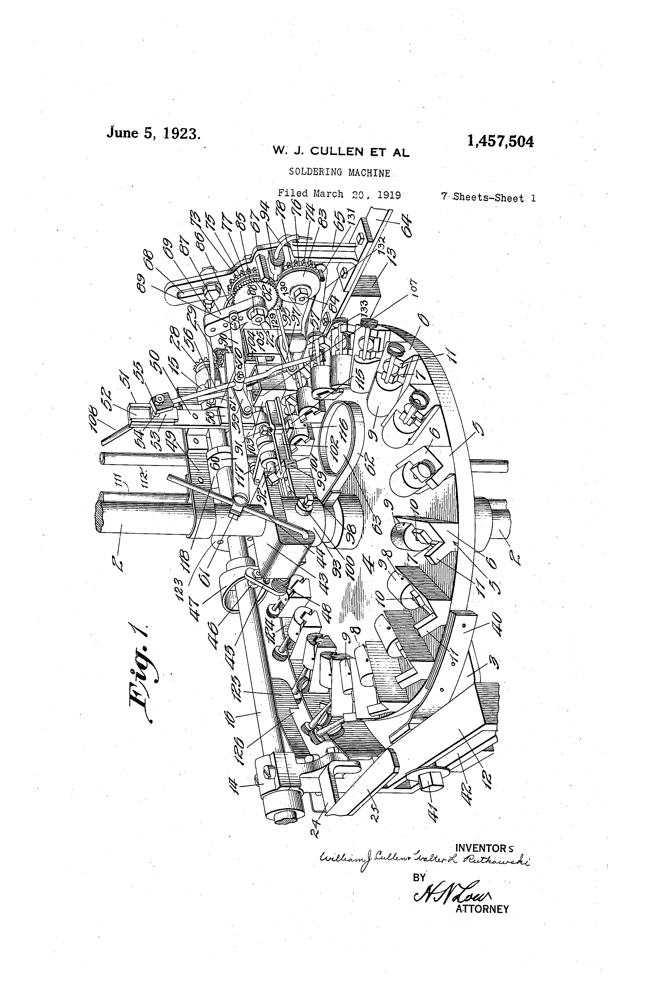
Referring to the drawings:
indicates the main base of the machine, which supports a vertical stationary adjustable shaft or standard 2. Suitably secured to the shaft 2 is a bracket member 3 which 80 supports a table 4 adapted to be intermittently rotated about the shaft 2.
The table 4 carries adjacent its periphery a plurality of cap seats and nozzle retaining members designated as a whole by the 85 numeral 5. These seats are preferably formed of a base member 6 secured to the table and at an angle therewith so that when the seat with the cap and nozzle properly arranged thereon are in alignment with 80 the soldering mechanism the line of contact between the nozzle and cap will be presented upwardly as nearly as possible to admit the access of the soldering iron. The caps are retained in position on the inclined 85 base member 6 by a horizontal shoulder 7 against which the caps rest while being conveyed to the soldering station and during the soldering operation. Pivoted to the base member 6 as at 8 is a yieldable nozzle clamp 100 or holder 9 provided with a longitudinal recess 10 formed and adapted to engage and retain a nozzle in horizontal position across the top of the cap and to which the nozzle is to be soldered. The clamping member 9 105 may be yieldably actuated by either a spring or by gravity. Adjacent to the retaining shoulder 7 and projecting upwardly at substantially right angles with the inclined base 6 is an abutment 11 adapted to co-act 110
To dll whom, it may concern:
Be it known that William J. Cullen and Walteb L. Rutkowski, citizens of the United States, residing at the city of St. 6 Louis, in the county of same and State of Missouri, have invented certain new and useful Improvements in Soldering Machines, of which the following is a specification.
The invention relates to automatic mecha10 nism for soldering screw caps to the sides of spouts, or for performing a soldering operation on other articles for which the mechanism is adapted, and has for its objects to save hand labor, to perform the operation on 15 successive articles at a relatively high speed so that the daily output is large in quantity with a minimum of labor, to use an unvariable minimum amount of solder, and to perform the operation accurately so that the fin20 ished articles are uniform for handling, boxing and use.
With such objects in view, as well as other advantages which may be incident to the use of the improvements, the invention con25 <sub>s</sub>i<sub>s</sub>ts in the parts and combinations thereof hereinafter set forth and claimed, with the understanding that the several necessary elements constituting the same may be varied in proportions and arrangement without de30 parting from the nature and scope of the invention.
In order to make the invention more clearly understood there are shown in the accompanying drawings means for carrying the 35 same into practical effect, without limiting the improvements, in their useful applications, to the particular construction which, for the purpose of explanation, have been made the subject of illustration. In the 40 said drawings:—
Fig. 1 is a perspective viOw of the main portion of the machine.
Fig. 2 is a front elevation of the entire machine on a smaller scale.
<sup>45</sup> Fig. 3 is an elevation of the upper part of the machine from the same point of view as in Fig. 2, but on a larger scale.
Fig. 4 is an elevation of the upper part of the machine viewed from the right hand of 50 Fig. 3.
Fig. 5 is a plan view of the machine, with the central standard and piping shown in section.
Fig. 6 is a plan view of the table and 55 means for rotating the same, certain parts
1,467,604 with the clamp 9 in retaining a nozzle in proper relation with the cap and to limit the inward movement of the nozzle within the clamp 9. The described arrangement of parts insure a proper and uniform positioning of the caps and nozzles relative to each other prior to permanently uniting the same by the soldering mechanism.
Fixed at each end of the bracket 3 are blocks 12 and 13 to which are secured bearing members 14 and 15 which rotatably support a horizontal drive shaft 16. Motive power is transmitted to the entire machine through the medium of a drive pulley 17 detachably secured to the flrive shaft 16 by the following clutch mechanism. Slidably keyed to the shaft 16 by means of a feather key 18 is a collar Ϊ9 provided with a peripheral groove 20 adapted to receive pins 21 of a yoke member 22. The yoke 22 is pivoted as indicated at 23 to a bracket 24 secured to the bearing 14 and is provided with an operating handle 25. One face of ,the collar 19 is provided with a plurality of pins 26 which are adapted to be engaged by similar pins 27 projecting from the hub of the drive pulley 17. When it is desired to transmit power from the drive pulley 17 to the drive shaft 16 and its associated parts <sup>30</sup> the collar 19 is shifted along the shaft 16 until the pins 26 are engaged by and mesh with the pins 27 of the rotating drive pulley 17 thus causing the drive pulley, clutch collar and drive shaft to rotate in unison.
An intermittent rotation is imparted to the table or bed 4 by means of the following described mechanism. Fixed to the drive shaft 16 is a beveled pinion 28 which meshes with and drives a similar beveled pinion 29 fixed to a comparatively short vertical shaft 30 supported by bracket members 31 secured to the block 13. The lower end of the shaft 30 is provided with a crank arm 32 which is connected by means of a connecting rod 33 with one end of an oscillating arm 34 mounted on the shaft 2 and beneath the table 4. The outer portion of this arm projects through a slot 35 in the block 13 and is supported therein. The arm 34 is provided with an offset portion 36 adjacent the outer periphery of the table 4 which constitutes a seat for a latch member 37 which is pivoted therein for vertical movement. The latch 37 is preferably in the form of a plate and is normally held in a raised position and in yieldable contact with the under face of the table 4 by means of a spring 38, Fig. 7. The under face of the table 4 is provided with a plurality of downwardly extending pins or studs 39 corresponding in number with the cap seats 5 and adapted to be engaged successively by the latch 37 upon each oscillation of the arm 34 thus imparting an intermittent or step by step rotation to the table 4. In order that the impetus occasioned by the actuation of the table by the arm 34 will not cause the table to ride past the desired point or more than one step there is provided a brake shoe 40 which is adjustably secured 70 by means of a bolt 41, (Fig. 1), in a slot 42 in the block 12 and which constantly bears against the outer periphery of the table 4 thus furnishing the desired frictional resistance against the action of the arm 34 and insuring an accurate alignment of the cap seats 5 with the soldering mechanism presently to be described.
Secured to the shaft 2 is a bracket 43 in which is journalled an oscillating lever arm 44. To one end of the arm 44 is fixed a crank arm 45 which carries an anti-friction roller 46 adapted to engage a cam 47 fixed to the drive shaft 16. The arm and roller i are held in contact with the cam 47 by a coiled spring 48 which encircles the portion of the lever arm 44 which extends out of <sup>;</sup> the bracket 43 and which has each end re<sup>;</sup> spectively attached to the bracket 43 and the crank arm 45. Fixed to the shaft 2 above the bracket 43 is a horizontal bracket 49 which carries at its outer end a vertical ’ plate 50. Secured to the upper end of the I plate 50 is a guide 51 having a vertical rei cess 52 with under cut walls adapted to re. tain a vertically reciprocable slide block 53. The slide 53 is provided with a trunnion 54 to which is attached a block 55 which carries a downwardly extending brush rod 56 provided at its lower end with a brush 57. The plate 50 has fixed thereto at its lower extremity a block 58 to which it attached a crank arm 59. The crank arm 59 is operatively connected with the lever arm 44 by a link 60 and a swivel 61 and carries a swivel block 61 through which the brush rod 56 passes thus forming an operative connection therewith. Fixed to the shaft 2 is a bracket 62 which supports a flux pan 63 in the path of the brush 57 and into which the same is intermittently dipped with each oscillation of the brush and rod.
Secured to the upper face of the block 13 is a plate 64 which forms a support for a bracket 65. Journalled in the bracket 65 is a stud shaft 66, (Figs. 4-8-9) which carries a frame 67 adapted to be rocked upon the said shaft and which is provided with a slot 68 in its upper portion. The frame 67 is rocked upon the shaft 66 by a connecting rod 69 which is adjustably attached in the slot 68 and is connected at its other end with an eccentric strap 70 riding upon an eccentric 71 fixed to the drive shaft 16. Mounted in the frame 67 is a rotatable shaft 72 to which is fixed a spur gear 73 which meshes with a spur gear 74 keyed to the shaft 66. Spaced from the faces of the gears 73 and 74 by washers or space plates 75 and 76 and keyed to the shafts 66 and 72 re
100
105
110
115
120
130
1,457,504 a step by step feed of the solder in the guides 94 and 95 supported by the frame 67 in addition to and independent of the said frame. When the frame 67 rocks back to its initial position, shown in (Fig. 9), <sup>70 </sup>the pawl 86 disengages itself from the ratchet wheel 85 allowing the solder feed disks to rotate freely and to roll upon the solder back to the point where they Will again be actuated to feed more solder to <sup>75 </sup>the soldering station.
If for any reason the operator does not insert a cap and spout in any one of the retaining devices as it passes: it is desirable to prevent solder from being fed forward <sup>80 </sup>for that particular station by solder feed disks 77 and 78. This is accomplished by lever 127 preventing pawl 86 from engaging ratchet 85 as frame 67 is rocked forward. The free end of lever 127 is located under and <sup>85 </sup>normally’contacts with pawl 86, is pivoted at 128, on a stud secured into side of rod 90, the upper end of a connecting rod 129 is hooked into end of lever 127, its lower end is secured to a plate 130, which is hinged at <sup>90 </sup>131 dn the end of a fixed arm 132 which is secured to bracket 105. This plate is formed so as to be weighted at one end and to be unevenly balanced and to gravitate.
If there is a spout in position in retaining <sup>05 </sup>device 5 when moving into soldering position, the large screwed portion of the spout will pass under and lift the offset portion 133 of the plate 130 thus causing the free end of lever 127 to be depressed away from pawl 1°° 86 allowing it to function properly. If spout is absent when moving into soldering position plate 130 will not be lifted and lever 127 will prevent pawl 86 from engaging ratchet 85. 105
The collar 93 has projecting therefrom a bracket 98 recessed to receive a slide 99 which is retained therein by overhanging plates 100. The slide 99 is bifurcated at one end as at 101 for a pivotal connection with one end 110 of a solder iron arm 102 which carries at substantially its middle a solder iron 103.
. The free end of the solder iron arm operates in a vertical slot 104 in a bracket 105 se ured to the block 13 and is provided with a weight 115 106 at its outer end to normally tend to hold the arm and soldering iron in soldering position. The soldering iron 103 is constructed with a hollow head forming a flame chamber 107 into which projects a pipe 108 which 120 furnishes a jet of flame for heating the soldering iron 103. Fuel is supplied to the pipe 108 from a mixing chamber 109 secured to the shaft 2 by a bracket 110. Air and gas are admitted in proper proportions to 125 the chamber 109 from pipes 111 and 112 and the flow thereof regulated by valves 113 and 114 respectively.
The solder iron is vertically actuated by a lever 115 mounted on the stationary shaft 130 spectively are two co-acting solder feed disks 77 and 78 provided with serrated peripheries and adapted to grip and feed solder in wire form to the soldering mechanism. The 5 solder is Supplied in wire form from a reel (Fig. 11) mounted to rotate freely upon a shaft 80 fixed to a box 81 supported by the base 1 of the machine. Against the faces of the solder feed disks 77 and 78 is another 10 set of space plates 82 and 83 respectively.
The plate 83 is held from displacement and against the gear 74 by a nut 84. Keyed to the shaft 72 and adjacent to the plate 82 is a ratchet wheel 85 adapted to be engaged by 15 a pawl 86 pivoted to an arm 87 mounted freely upon the shaft 72 and held thereon by a' nut 88. The arm has adjustably secured thereto as at 89 one end of a rod 90 which is pivoted to a stationary bracket 91 20 fixed to a horizontal stationary shaft or rod 92 supported at each end respectively by the bracket 15 and a collar 93 fixed to the vertical shaft 2 of the machine.
The solder is supported on the frame 67 <sup>25</sup> and in proper alignment with the feed disks 77 and 78 by tubular guide members 94 and 95 which are fixed to the frame in any preferred manner. The upper end of the guide 95 is yieldably supported upon <sup>30</sup> the frame 67 in a slot 96, (Fig. 4), which permits the free movement of the said frame. The lower end of the guide 95 adjacent the soldering station is supported by a bracket 97 secured to the plate 64.
<sup>35</sup> This arrangement of parts results in that when the frame 67 is rocked to the left (Fig. 8) and about its supporting shaft 66 under the action of the eccentric 71 and connecting rod 69, it carries the shaft 72, 40 spur gear 73, solder feed disk 77, ratchet wheel 85 and arm 87 bodily in an arc concentric with said supporting shaft 66. The arm 87'being free upon the shaft 72 also swings about its pivotal connection 89 the 45 same being substantially stationary owing to the relatively small arc traversed by the frame 67 during it& oscillation. This results in that the pawl 86 engages the teeth of the ratchet wheel 85 which is keyed to the 50 shaft 72 and holds the same stationary with respect to the arm 8?. The upper solder feed disk 77 and spur gear 73 ’being also keyed to the shaft 72 are held stationary relative to the arm 87. The effect of this is 55 to cause the shaft 72 and parts keyed thereto to rotate with respect to and independent of. any movement of the frame 67. This causes the upper spur gear 73 to rotate the lower spur gear 74. which is keyed to the 60 frame supporting shaft 66. independently of the movement of the frame 67 about the shaft 66 and causes the rotation of the lower solder feed disk 78 which is also keyed to the shaft 66. The intermittent rotation of 65 the two solder feed disks 77 and 78 causes
-½
1,467,604 one arm of which extends under the solder iron arm and engages a set screw 116 therein and the other arm carries an anti-friction roller 117 for engagement with a cam 118 5 fixed to the drive shaft 16. The solder iron is also reciprocated longitudinally to effect a proper distribution of the solder on the joint by means of a lever 119 (Figs. 5 and 10), pivotally mounted at 120 on the station16 ary shaft 92. One arm of the lever 119 is pivotally connected with the under side of the slide 99 as at 121 and the other arm is provided with an anti-friction roller 122 adapted to engage a pin cam 123 to cause 15 a rapid lateral oscillatory movement of the lever 119.
When the soldered joint between the nozzle member and the serew cap has been completed the soldering iron 103 is raised <sup>20</sup> by the continued rotation of the cam 118 and the completed cap and nozzle is intermittently carried around by the table to an arcuate fixed cam 124 eccentrically mounted with respect to the said table and adjacent <sup>25</sup> the periphery thereof which is engaged by the cap portion of the nozzle during its travel and gradually withdraws the same from the clamps 9, (Fig. 1). As the intermittent rotation of the table continues and <sup>30</sup> before the cap and nozzle is completely withdrawn from the clamp it engages beneath a second cam 125 superposed above the cam 124 which assists in completely removing the nozzle from .the clamps. The cam 125 is 35 recessed as at 126 to allow the joined cap and nozzle to fall to a suitable place of deposit.
14 sheets
Sheet 1 Sheet 2 Sheet 3 Sheet 4 Sheet 5 Sheet 6 Sheet 7 Sheet 8 Sheet 9 Sheet 10 Sheet 11 Sheet 12 Sheet 13 Sheet 14
Every citation, both ways
| Document | Relation | Office | Cited during |
|---|---|---|---|
| US11008153B2 | Cited by | United States of America | Applicant |
| US10723538B2 | Cited by | United States of America | Applicant |
| US10065256B2 | Cited by | United States of America | Search report |
| US11702271B2 | Cited by | United States of America | Applicant |
| US2701778A | Cited by | United States of America | Search report |
| US10923691B2 | Cited by | United States of America | Applicant |
| US11320086B2 | Cited by | United States of America | Applicant |
| US10823326B2 | Cited by | United States of America | Applicant |
| US11548717B2 | Cited by | United States of America | Applicant |
| US10497908B2 | Cited by | United States of America | Applicant |
| US11204127B2 | Cited by | United States of America | Applicant |
| US2017120362A1 | Cited by | United States of America | Pre-grant |
| US10495250B2 | Cited by | United States of America | Applicant |
| US2549868A | Cited by | United States of America | Search report |
Numbers
- Application
- 28378519
Titles
- English
- Soldering machine
Classification
- CPC, 1
- B23K3/08
- IPC, 1
- B23K3 08