Support for a self-contained breathing apparatus
Summary by NHIP
Wearable breathing apparatus support
The wearable support features a structural frame with a cylinder cradle and a separate glider that elevates the gas cylinder above the cradle. The glider includes resilient arms that move between a proud gliding position and a retracted position flush with or below the retaining surface.
Claim Score by NHIP
Abstract
A support for a breathing apparatus including a cylinder cradle with a retaining surface for retaining a cylinder of compressed gas and a cylinder glider including a gliding element, the gliding element configured to support the cylinder above the retaining surface, wherein the cylinder glider is longitudinally separated from the retaining surface of the cylinder cradle.
Term
16.8 yearsleft in the term
Expires 29 July 2043, including 891 days of term adjustment.
- Priority and filed
- Granted
- Today
- Expires
19 claims: 3 independent, 16 dependent
- 1A wearable support for a breathing apparatus comprising:a structural frame extending in a longitudinal direction substantially parallel to the back of a wearer during use;a cylinder cradle comprising a retaining surface for retaining a cylinder of compressed gas;and a cylinder glider comprising a gliding element including at least one resilient arm, the gliding element configured to support the cylinder above the retaining surface, and to separate the cylinder from the retaining surface of the cylinder cradle and prevent the cylinder from directly contacting the retaining surface of the cylinder cradle;wherein the cylinder glider is separated from the retaining surface of the cylinder cradle in a direction longitudinal to the structural frame;wherein the glider extends across the entire width of the structural frame.
- 13Broadest claimClaim Score 73, broad(NHIP)A wearable support for a breathing apparatus, comprising:a structural frame extending in a longitudinal direction substantially parallel to the back of a wearer during use;a cylinder cradle comprising a retaining surface for retaining a cylinder of compressed gas;a cylinder glider including at least one resilient arm;wherein the cylinder glider is separated from the retaining surface of the cylinder cradle in a direction longitudinal to the structural frame wherein the cylinder glider comprises a concave surface.
- 16A wearable support for a breathing apparatus, comprising:a structural frame extending in a longitudinal direction substantially parallel to the back of a wearer during use;a cylinder cradle comprising a retaining surface for retaining a cylinder of compressed gas;a cylinder glider including at least one resilient arm;wherein the cylinder glider is separated from the retaining surface of the cylinder cradle in a direction longitudinal to the structural frame;where the cylinder glider is in direct contact to the cylinder cradle.
Independent claims3
63 paragraphs in 5 sections, as filed
CROSS-REFERENCE TO RELATED APPLICATIONS
0001This application claims priority to European Application No. 20164985.2, filed on Mar. 23, 2020, the entire contents of which being fully incorporated herein by reference.
0002The disclosure relates to a support for a breathing apparatus.
BACKGROUND
0003A typical support for a breathing apparatus, such as a self-contained breathing apparatus (SCBA), comprises a frame configured for attachment to the back of a user, and a cylinder support on which a breathing gas cylinder can be secured.
0004After a breathing gas cylinder has been exhausted, it must be replaced. In an emergency situation, it is desirable that a breathing gas cylinder can be installed and/or replaced rapidly.
0005It is therefore desirable to provide an improved support arrangement.
BRIEF DESCRIPTION OF THE INVENTION
0006According to an aspect, there is provided a support for a breathing apparatus comprising: a cylinder cradle comprising a retaining surface for retaining a cylinder of compressed gas; and a cylinder glider comprising a gliding element, the gliding element configured to support the cylinder above the retaining surface; wherein the cylinder glider is longitudinally separated from the retaining surface of the cylinder cradle.
0007The support may be a back plate of a breathing apparatus, such as a self-contained breathing apparatus. The principles of this disclosure may be equally applied to other breathing apparatuses, such as closed-circuit breathing apparatuses having replaceable gas cylinders.
0008The cylinder glider may enable easy installation, removal and/or replacement of the cylinder. By locating the glider separately from the cradle, rather than as part of the cradle, the surface area of the cradle for contact with the cylinder can be maximised. The support may be used with cylinders of a range of dimensions. Longitudinal separation does not necessarily mean that there is a space between the cradle and glider. The cradle and glider may be immediately adjacent each other in a longitudinal direction.
0009The support may be configured to be arranged on a user's back. The support may be arranged, in use, so as to overlie a user's back. The support may extend in a longitudinal direction. The longitudinal direction may be, in use, a substantially vertical direction. The longitudinal direction may be substantially parallel to the direction of extension of a user's spine. The support may be configured for installation of a gas cylinder in the longitudinal direction. The support may be a backplate.
0010The retaining surface may comprise a gripping surface. The retaining surface may have a high coefficient of friction with a cylinder such that the cylinder is not able to easily slide over the retaining surface. The retaining surface may have a generally concave circular form so as to conform to the periphery of a cylinder of compressed gas. The retaining surface may allow full contact with the cylinder and provide a secure connection which is resilient to impact and vibration.
0011The gliding element may comprise a gliding surface. The gliding surface may comprise a gliding protrusion. The gliding surface may comprise a plurality of gliding protrusions. The gliding element may have a low coefficient of friction with a cylinder such that the cylinder is able to glide freely along the gliding element. The cylinder glider may comprise a plurality of gliding elements.
0012The gliding element may be configured to support the cylinder above the retaining surface, such that the cylinder is raised relative to the retaining surface. The gliding element may be configured to support the cylinder above the retaining surface, such that the cylinder is proud of the retaining surface. The gliding element may be configured to support the cylinder above the retaining surface such that, when installing a cylinder on the support, the contact between the cylinder and the retaining surface is reduced, such that the position of the cylinder can be adjusted more easily.
0013The gliding element may be configured to sit proud of the retaining surface. It should be understood that this means that the gliding element may be raised relative to the retaining surface. The gliding element may protrude relative to the retaining surface. The gliding element may generally be configured to contact a cylinder during its attachment to the support and space the cylinder apart from the receiving surface, so as to inhibit the cylinder from contacting the receiving surface.
0014The glider may extend laterally across the support. The gliding element may extend laterally across the support. The gliding element may comprise a gliding surface which extends laterally across the support.
0015The gliding element may be moveable between a) a gliding position in which the gliding element sits proud of the retaining surface and the support surface; and b) a retracted position in which the gliding element is flush with, or retracted below the retaining surface. The gliding element may be depressible into the retracted position. The gliding element may be compressible into the retracted position.
0016The support may further comprise means for clamping a cylinder (i.e. urging a cylinder against the retaining surface). This may allow the cylinder to be fixed in position for use, and to be released after use. The gliding element may be configured to be moved into the retracted position by the clamping of a cylinder on the support, (i.e. by a force applied on the gliding element by the cylinder from the action of the clamping means). The means for clamping a cylinder may comprise a generally circular band through which a cylinder can be passed, and which can be tightened to clamp the cylinder against the retaining surface. The circular band may be adjustable such that the support can accommodate cylinders of different dimensions. The means for clamping a cylinder may comprise a cylinder strap and adjustable buckle arrangement.
0017The cylinder glider may be resiliently deformable so as to move the gliding element between the gliding position and the retracted position. The cylinder glider may be hinged so as to provide the resilient deformability. The cylinder glider may comprise a resiliently deformable material. The gliding element may be resiliently deformable. The gliding element may comprise a resiliently deformable material. The material may be conductive. The material may be flame retardant. The material may provide a good combination of strength, resilience, self-lubricating properties and an appropriate flexural modulus so as to provide a high degree of flex without plastic deformation. The material may further comprise fillers and/or additives. The material may be electrostatically dissipating. The material may have reduced surface resistivity. The material may have modified impact properties. Filler, conductive additives, or flame-retardant additives may be added to the material to enhance the properties. The glider may be manufactured from a polymeric material. The glider may be manufactured from polyamide 6, or polyamide 6/6. The glider may be manufactured from polyamide 6, or polyamide 6/6 comprising 10% carbon fibres and 25% glass fibres.
0018The support may comprise longitudinally spaced first and second ends, the second end comprising a pressure reducer valve. The cylinder glider may be positioned between the cylinder cradle and the first end. The cylinder glider may be positioned on the opposite side of the cylinder cradle to the pressure reducer valve. During installation of a cylinder, the cylinder may contact the cylinder glider before contacting the cylinder cradle.
0019The gliding element may be arranged so as to guide the cylinder into a central position on the support. This may provide a self-aligning feature of the support. The gliding element may be a guiding element. The guiding element may comprise a concave surface for contact with the gas cylinder. The gliding element may be arranged centrally on the support.
0020The gliding element may have a lower coefficient of friction than the retaining surface. This may allow the cylinder to more easily slide along the gliding element than the retaining surface. This may allow for ease of insertion of a cylinder.
0021The cylinder glider may be immediately adjacent the cylinder cradle. This may provide a compact arrangement of the glider and cradle on the support. The closer the cylinder glider is to the cylinder cradle, the smaller the contact area between the cylinder and the cradle.
0022The cylinder glider may be removably attached to the support. This may enable use of the support with or without the glider. Easy removal may enable ease of cleaning or maintenance of the glider and the support. Furthermore, the glider may be easily replaced if it is damaged without replacing the entire support.
0023The cylinder glider may comprise a plurality of gliding elements for contacting the cylinder. The gliding elements may be spaced laterally. The cylinder glider may comprise 3 gliding elements. The shape, location and dispersion of the gliding elements may be selected to provide guiding of a cylinder on installation. The shape, location and dispersion of the gliding elements may be selected to provide self-alignment of a cylinder on installation. The gliding elements may be located substantially symmetrically about a central longitudinal axis of the support.
0024The cylinder cradle may comprise a resiliently deformable material. The retaining surface may comprise a resiliently deformable material. The cylinder cradle may be conductive. The cylinder cradle may be flame retardant. The cylinder cradle may be self-extinguishing. The cylinder cradle may be formed from an elastomeric material. The cylinder cradle may formed from a rubber. The cylinder cradle may be formed from Chloroprene rubber. The material may be carbon loaded to provide improved electrical conductive properties. Chloroprene rubber may provide good resistance to ozone cracking, heat aging and chemical attack.
0025According to a further aspect there is provided a breathing apparatus, optionally a self-contained breathing apparatus, comprising a support according to the first aspect described above.
0026The skilled person will appreciate that except where mutually exclusive, a feature described in relation to any one of the above aspects may be applied mutatis mutandis to any other aspect. Furthermore except where mutually exclusive any feature described herein may be applied to any aspect and/or combined with any other feature described herein.
BRIEF DESCRIPTION OF THE FIGURES
0027Embodiments of the present invention relate to will now be described by way of example only, with reference to the Figures, in which:
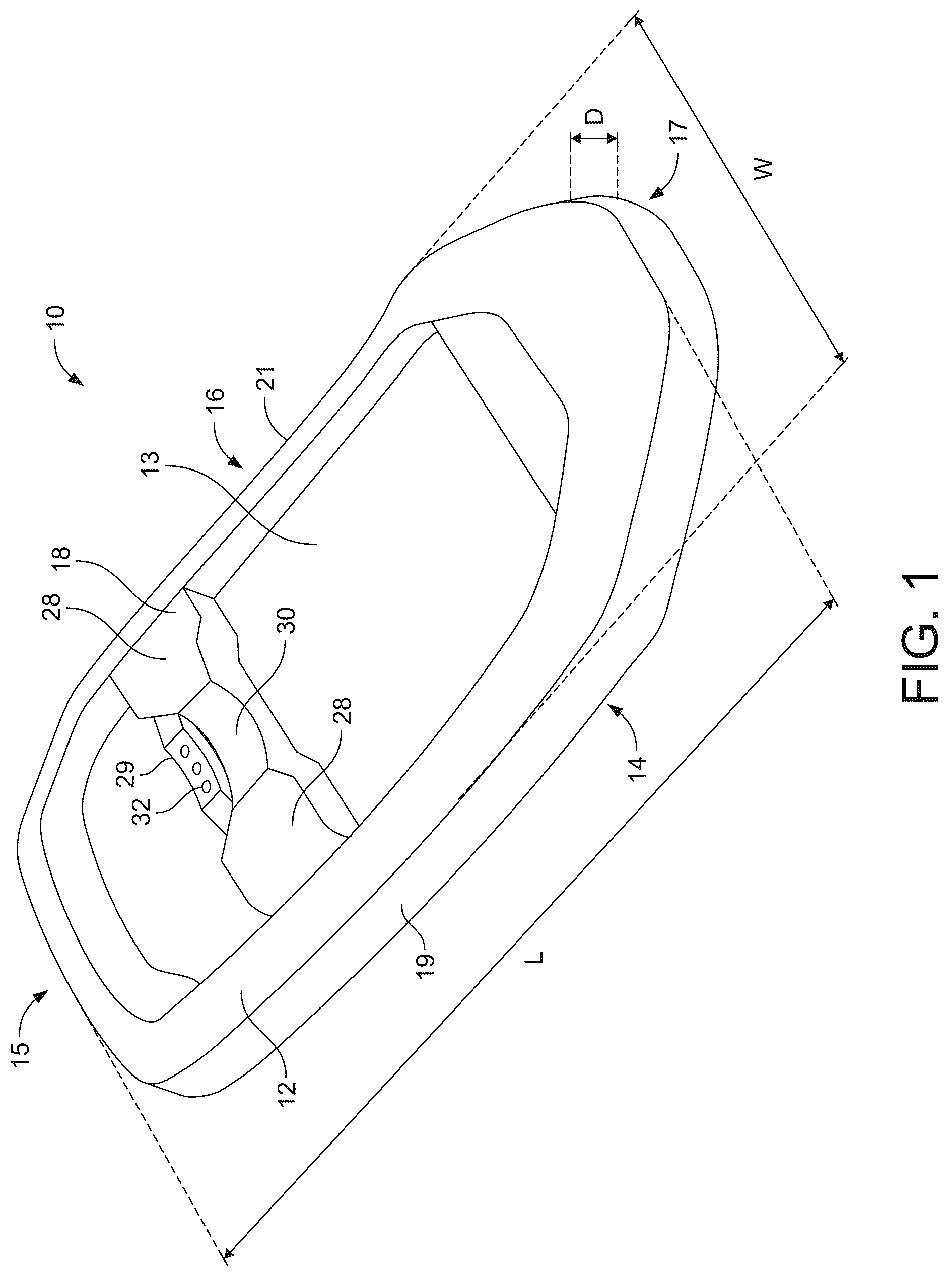
0028<figref idref="DRAWINGS">FIG. <b>1</b></figref> schematically shows a perspective view of a support for a breathing apparatus according to the present invention;
0029<figref idref="DRAWINGS">FIG. <b>2</b></figref> schematically shows an exploded perspective view of the support of <figref idref="DRAWINGS">FIG. <b>1</b></figref>;
0030<figref idref="DRAWINGS">FIG. <b>3</b></figref> schematically shows a side cross-sectional view of the support of <figref idref="DRAWINGS">FIGS. <b>1</b> and <b>2</b></figref> taken along line A-A in <figref idref="DRAWINGS">FIG. <b>1</b></figref>, showing a glider in a gliding position and also including a gas cylinder (also shown in cross-section); and
0031<figref idref="DRAWINGS">FIG. <b>4</b></figref> schematically shows a side cross-sectional view of the support of <figref idref="DRAWINGS">FIGS. <b>1</b> and <b>2</b></figref> taken along line A-A in <figref idref="DRAWINGS">FIG. <b>1</b></figref>, showing a glider in a retracted position and also including a gas cylinder (also shown in cross-section).
DETAILED DESCRIPTION OF THE FIGURES
0032With reference to <figref idref="DRAWINGS">FIG. <b>1</b></figref>, the support <b>10</b> for a breathing apparatus comprises a substantially rectangular structural frame <b>12</b> defining a central opening <b>13</b>. The support <b>10</b> comprises an inner side <b>14</b>, an outer side <b>16</b>, an upper end <b>15</b>, a lower end <b>17</b>, a left side <b>19</b> and a right side <b>21</b>. The frame <b>12</b> extends in a longitudinal direction between the upper end <b>15</b> and the lower end <b>17</b>, defining a length L. The frame <b>12</b> extends in a lateral direction between the left side <b>19</b> and the right side <b>21</b>, defining a width W. The frame <b>12</b> extends in a depth direction between the inner side <b>14</b> and the outer side <b>16</b>, defining a depth D. In use, the inner side <b>14</b> is arranged adjacent to a user's back, and the outer side <b>16</b> faces away from a user's back. Straps (not shown) may be provided to permit a user to don the support <b>10</b> on their back.
0033As can be seen in <figref idref="DRAWINGS">FIG. <b>2</b></figref>, the frame <b>12</b> further comprises a laterally extending bridge portion <b>36</b>, to which a cylinder glider <b>26</b> and a cylinder cradle <b>18</b> may be removably attached on an outer side <b>16</b> of the support (as will be discussed below). The support <b>10</b> further comprises a cylinder clamping band <b>20</b> (shown in <figref idref="DRAWINGS">FIG. <b>4</b></figref>). The clamping band <b>20</b> comprises an adjustable loop which can be tightened around the cylinder <b>22</b>.
0034The cylinder cradle <b>18</b>, removably attached on an outer side <b>16</b> of the support, comprises two shoulder portions <b>28</b> and a retaining surface, in this embodiment, a central saddle <b>30</b>. It will be appreciated that the invention is not limited to the saddle as hereindefined, and that other arrangements of the retaining surface may be contemplated by the skilled person. The cradle <b>18</b> extends laterally across the central opening <b>13</b> of the frame <b>12</b>. The cradle <b>18</b> is located approximately one-third of the length L from the upper end <b>15</b> to the lower end <b>17</b>. A gas cylinder <b>22</b> can be installed onto the support <b>10</b> in a direction D extending from the upper end <b>15</b> to the lower end <b>17</b>, and supported on the cradle <b>18</b> and held in place by the clamping band <b>20</b>. As shown in <figref idref="DRAWINGS">FIGS. <b>3</b> and <b>4</b></figref>, the outer side <b>16</b> further comprises a pressure reduction valve <b>27</b> towards the lower end <b>17</b>, which is configured to connect with a cylinder valve <b>24</b> on the cylinder <b>22</b> in order to provide gas flow from the cylinder <b>22</b>, via the valves <b>24</b>, <b>27</b> to a user's breathing mask (not shown). The skilled person will appreciate that the gas cylinder <b>22</b> may also be inserted in the opposite direction (i.e. from the lower end to the upper end), and achieve some benefits of the invention as discussed throughout this application.
0035The saddle <b>30</b> has a concave circular form, which is generally conformable to the periphery of a cylinder <b>22</b>, to ensure full contact is maintained with the cylinder <b>22</b> when the cylinder <b>22</b> is clamped to the support <b>10</b> with the clamping band <b>20</b>. The saddle <b>30</b> is manufactured from a resiliently deformable elastomeric material, in this example Chloroprene rubber. The material comprises a conductive additive, in this example carbon. The conductive additive improves the properties of the material for use in explosive environments. Further additives may increase the stiffness and tensile strength of the material.
0036The support <b>10</b> is configured for attachment to a user's back via a strap arrangement (not shown), which can be attached to the support <b>10</b> at strap fixing points on the inner side <b>14</b> of the frame <b>12</b>. The strap arrangement can be placed over a user's shoulders such that the support <b>10</b> can be supported on a user's back.
0037The support <b>10</b> further comprises a cylinder glider <b>26</b> located on the outer side <b>16</b>, and longitudinally separated from the cradle <b>18</b>. The glider <b>26</b> extends laterally across the support <b>10</b>. In this embodiment, the glider <b>26</b> is located immediately adjacent an upper side of the cradle <b>18</b> (i.e. towards the upper end <b>15</b> of the frame <b>12</b>, on the opposite side of the cradle <b>18</b> to the pressure reduction valve <b>27</b>). In other embodiments, the glider <b>26</b> may be located immediately adjacent a lower side of the cradle <b>18</b> (i.e. between the cradle <b>18</b> and the pressure reduction valve <b>27</b>), or may be spaced further apart from the upper or lower side of the cradle <b>18</b>.
0038The glider <b>26</b> comprises a gliding element, in this embodiment a gliding surface <b>29</b> defining three gliding protrusions <b>32</b>. The gliding surface <b>29</b> extends laterally across the glider. The gliding protrusions <b>32</b> are spaced laterally across the gliding surface <b>29</b>. The glider <b>26</b> is hinged at four positions <b>34</b><i>a</i>, <b>34</b><i>b</i>, <b>34</b><i>c</i>, <b>34</b><i>d </i>so that the gliding surface <b>29</b> (and therefore the gliding protrusions <b>32</b>) can be resiliently deformed in the depth direction. In other embodiments, the glider <b>26</b> may comprise a resiliently deformable material in order to provide the resilient deformability in the depth direction. In further embodiments, the glider <b>26</b> may comprise a gliding surface <b>29</b> supported by a leaf or compression spring arrangement below the gliding surface, so as to be resiliently deformable in the depth direction. The resilient deformability of the glider <b>26</b> in the depth direction allows the glider <b>26</b> to be moved between a gliding position and a retracted position. The gliding surface <b>29</b> and gliding protrusions <b>32</b> are biased into the gliding position.
0039In the gliding position (<figref idref="DRAWINGS">FIG. <b>3</b></figref>), the gliding protrusions <b>32</b> of the gliding surface <b>29</b> protrude outwardly of the saddle <b>30</b> in a depth direction. In other words, a distance between the gliding protrusions <b>32</b> of the gliding surface <b>29</b> and the frame <b>12</b> in a depth direction is greater than a distance between the saddle <b>30</b> and the frame <b>12</b> in a depth direction. This arrangement means that during installation of a cylinder <b>22</b> onto the support <b>10</b>, the cylinder <b>22</b> is held away from the saddle <b>30</b> due to the contact with the gliding protrusions <b>32</b> of the gliding surface <b>29</b>, as will be discussed below. By reducing contact with the saddle <b>30</b> during installation, ease of installation of the cylinder <b>22</b> can be improved.
0040In the retracted position (<figref idref="DRAWINGS">FIG. <b>4</b></figref>), the gliding protrusions <b>32</b> of the gliding surface <b>29</b> are deformed in the depth direction, towards the support <b>10</b>, such that the gliding protrusions <b>32</b> are level with the saddle <b>30</b>. In other words, the distance between the gliding protrusions <b>32</b> and the frame <b>12</b> in a depth direction is the same as the distance between the saddle <b>30</b> and the frame <b>12</b> in a depth direction. This means that after installing the cylinder <b>22</b> onto the support <b>10</b>, the gliding protrusions <b>32</b> of the gliding surface <b>29</b> can be retracted away (or lowered) such that full contact between the cylinder <b>22</b> and saddle <b>30</b> can be effected. This provides an arrangement in which the cylinder <b>22</b> is securely held in position by contact with the saddle <b>30</b>, and provides resilience to impact and vibration.
0041As discussed above, the gliding surface <b>29</b> defines three gliding protrusions <b>32</b>. The gliding protrusions <b>32</b> are evenly spaced across the width of the gliding surface <b>29</b>. The gliding protrusions <b>32</b> are raised above the saddle <b>30</b> in a gliding position. The gliding protrusions <b>32</b> have a planar surface, but in other embodiments may be slightly curved so as to conform to the outer surface of a cylinder <b>22</b>, or may be hemispherical to provide point contact only. The gliding protrusions <b>32</b> provide a low-friction surface which allows a cylinder <b>22</b> to easily slide over the gliding protrusions <b>32</b>. The gliding protrusions <b>32</b> are arranged symmetrically about the longitudinal axis of the support <b>10</b> so as to provide a self-aligning feature for the cylinder <b>22</b>. For example, the two outer gliding protrusions <b>32</b> are configured to provide contact and guiding with larger diameter cylinders, and the central gliding protrusion <b>32</b> is configured to contact a smaller diameter cylinder, with guiding provided by the outer gliding protrusions <b>32</b>. The shape, height and dispersion of the gliding protrusions <b>32</b> can be adjusted to tailor the aligning feature.
0042The gliding protrusions <b>32</b> and the gliding surface <b>29</b> comprise a polymeric material such as Polyamide <b>6</b> or Polyamide <b>6</b>/<b>6</b>. The Polyamide <b>6</b> or Polyamide <b>6</b>/<b>6</b> further comprises 10% carbon fibres and 25% glass fibres. These materials provide a good combination of strength, resilience, self-lubricating properties and an appropriate flexural modulus so as to provide a high degree of flex without plastic deformation. Other materials may be contemplated by the skilled person. Filler, conductive additives, or flame-retardant additives can be added to the material to enhance the properties if necessary. Example materials properties are: flexural modulus of 9500 MPa and flexural strength of 200 MPa. It will be appreciated that a range of materials properties will be appropriate for the gliding protrusions <b>32</b> and gliding surface <b>29</b>.
0043In this embodiment, the gliding surface <b>29</b> comprises three gliding protrusions <b>32</b>. In other embodiments it will be appreciated that the gliding surface <b>29</b> may comprise a different number of gliding protrusions <b>32</b>. In an embodiment where only a single gliding protrusion <b>32</b> is provided, the gliding protrusion <b>32</b> may be centrally located on the gliding surface <b>29</b>. The gliding protrusion <b>32</b> may have a planar surface, but in other embodiments may be slightly curved so as to conform to the outer surface of a cylinder <b>22</b>, or may be hemispherical to provide point contact only. A curved surface may act to guide a cylinder <b>22</b> into a central position during installation.
0044As mentioned above, and as shown in <figref idref="DRAWINGS">FIG. <b>2</b></figref>, the glider <b>26</b> and cradle <b>18</b> are removably attached to the frame <b>12</b> at the bridge portion <b>36</b> of the frame <b>12</b>. The cradle <b>18</b> is attached to the bridge portion <b>36</b> by the engagement of barbs on the cradle (not shown) with corresponding slots in the bridge portion <b>36</b> (not shown), however other means of attachment will be contemplated by the skilled person.
0045The glider <b>26</b> comprises resilient arms <b>38</b> and locking tabs <b>40</b>. The resilient arms <b>38</b> can be deformed inwardly in a lateral direction, by action of the hinges <b>34</b><i>b</i>, <b>34</b><i>c </i>upon application of an inward force to the arms. This reduces the width of the glider <b>26</b>, such that the glider <b>26</b> can be inserted into a corresponding opening <b>42</b> of the bridge portion <b>36</b>. Upon release of the arms <b>38</b>, the glider <b>26</b> reverts to its original extended position. The tabs <b>40</b> cooperate with the periphery of the opening <b>42</b> in order to lock the glider <b>26</b> into position.
0046In use, a cylinder <b>22</b> is installed on the support <b>10</b> by moving the cylinder <b>22</b> in the direction D from the upper end <b>15</b> to the lower end <b>17</b> of the support <b>10</b>, passing the cylinder <b>22</b> through the clamping band <b>20</b>. During this movement, as the glider <b>26</b> is in the gliding position, raised above the saddle <b>30</b> of the cradle <b>18</b>, the cylinder <b>22</b> contacts the glider <b>26</b> as shown in <figref idref="DRAWINGS">FIG. <b>3</b></figref>. The glider <b>26</b> has a lower coefficient of friction with the cylinder <b>22</b> than the coefficient of friction between the cradle <b>18</b> and the cylinder <b>22</b>, and also has a smaller surface area in contact with the cylinder <b>22</b>. The cylinder <b>22</b> therefore easily glides along the glider <b>26</b> with minimal contact with the cradle <b>18</b>. The arrangement of the gliding protrusions <b>32</b> on the glider <b>26</b> guides the cylinder <b>22</b> so that it is centrally located on the width of the support <b>10</b>. The cylinder valve <b>24</b> is then connected to the reducer valve <b>27</b> on the support <b>10</b> (as shown in <figref idref="DRAWINGS">FIG. <b>4</b></figref>), and the clamping band <b>20</b> is tightened around the cylinder <b>22</b>. During this connection, the cylinder <b>22</b> applies a force on the glider <b>26</b> which moves the glider <b>26</b> into the retracted position. With the glider <b>26</b> in the retracted position, the cylinder <b>22</b> is able to fully contact the saddle <b>30</b> of the cradle <b>18</b>, thereby providing a secure and resilient connection of the cylinder <b>22</b> to the support <b>10</b> for cylinders of varying sizes. It will be appreciated by the skilled person that the glider <b>26</b> also helps with removal of the cylinder, as upon release of the clamping band <b>20</b>, the glider <b>26</b> will raise, thereby raising the cylinder and reducing the amount of cylinder surface area in contact with the saddle of the cradle <b>18</b>.
0047Although in this embodiment, gliding protrusions <b>32</b> of the gliding surface <b>29</b> are deformed by the cylinder <b>22</b> to the retracted position, resulting in the gliding protrusions <b>32</b> being level with the saddle <b>30</b>, it will be appreciated that, in other embodiments, the gliding protrusions <b>32</b> may be deformable to be lower than the saddle <b>30</b>, such that there is no contact between the gliding protrusions <b>32</b> and the cylinder in the retracted position. For example, the gliding protrusions <b>32</b> may be retracted into the glider <b>26</b> or the lateral bridge portion <b>36</b> of the frame <b>12</b>. A separate mechanism may be provided to move the gliding protrusions <b>32</b> into the glider <b>26</b> or the frame <b>12</b>, i.e. the movement of the glider <b>26</b> into the retracted position may be independent of the installation of a cylinder <b>22</b>.
0048For the avoidance of doubt, the present disclosure extends to the subject matter in the following numbered Paras:
0049Para 1. A support for a breathing apparatus comprising: <ul id="ul0001" list-style="none"><li id="ul0001-0001" num="0000"><ul id="ul0002" list-style="none"><li id="ul0002-0001" num="0050">a cylinder cradle comprising a retaining surface for retaining a cylinder of compressed gas; and</li><li id="ul0002-0002" num="0051">a cylinder glider comprising a gliding element, the gliding element configured to support the cylinder above the retaining surface;</li><li id="ul0002-0003" num="0052">wherein the cylinder glider is longitudinally separated from the retaining surface of the cylinder cradle.</li></ul></li></ul>
0053Para 2. A support according to Para 1, wherein the gliding element is configured to sit proud of the retaining surface.
0054Para 3. A support according to Para 1 or 2, wherein the glider extends laterally across the support.
0055Para 4. A support according to any preceding Para wherein the gliding element is moveable between: <ul id="ul0003" list-style="none"><li id="ul0003-0001" num="0000"><ul id="ul0004" list-style="none"><li id="ul0004-0001" num="0056">a) a gliding position in which the gliding element sits proud of the retaining surface; and</li><li id="ul0004-0002" num="0057">b) a retracted position in which the gliding element is flush with the retaining surface, or retracted below the retaining surface.</li></ul></li></ul>
0058Para 5. A support according to Para 4, the support further comprising means for clamping a cylinder, wherein the gliding element is configured to be moved into the retracted position by the clamping of a cylinder on the support.
0059Para 6. A support according to Para 4 or 5, wherein the cylinder glider is resiliently deformable so as to move the gliding element between the gliding position and the retracted position.
0060Para 7. A support according to Para 6, wherein the cylinder glider is hinged to provide the resilient deformability.
0061Para 8. A support according to any preceding Para, wherein the support comprises longitudinally spaced first and second ends, the second end comprising a pressure reducer valve, and wherein the cylinder glider is positioned between the cylinder cradle and the first end.
0062Para 9. A support according to any preceding Para, wherein the gliding element is arranged so as to guide the cylinder into a central position on the support.
0063Para 10. A support according to any preceding Para, wherein the gliding element has a lower coefficient of friction than the retaining surface.
0064Para 11. A support according to any preceding Para, wherein the cylinder glider is immediately adjacent the cylinder cradle.
0065Para 12. A support according to any preceding Para, wherein the cylinder glider is removably attached to the support.
0066Para 13. A support according to any preceding Para, wherein the cylinder glider comprises a plurality of gliding elements for contacting the cylinder.
0067Para 14. A support according to any preceding Para, wherein the cylinder cradle comprises a resiliently deformable material.
0068Para 15. A breathing apparatus, optionally a self-contained breathing apparatus, comprising a support as recited in any preceding Para.
Contents5
5 sheets
Sheet 1 Sheet 2 Sheet 3 Sheet 4 Sheet 5
Every citation, both ways
| Document | Relation | Office | Cited during |
|---|---|---|---|
| CN101366992A | Cites | China | Applicant |
| CN101879360A | Cites | China | Applicant |
| CN103656905A | Cites | China | Applicant |
| CN104027904A | Cites | China | Applicant |
| CN105764574A | Cites | China | Applicant |
| CN107823817A | Cites | China | Applicant |
| CN110101986A | Cites | China | Applicant |
| US2002078959A1 | Cites | United States of America | Search report |
| US2005035258A1 | Cites | United States of America | Applicant |
| US2008179367A1 | Cites | United States of America | Search report |
| US2009045657A1 | Cites | United States of America | Applicant |
| US2011048421A1 | Cites | United States of America | Search report |
| CN201248937Y | Cites | China | Applicant |
| US2014069427A1 | Cites | United States of America | Search report |
| US2015144137A1 | Cites | United States of America | Search report |
| US2015144674A1 | Cites | United States of America | Search report |
| CN205198735U | Cites | China | Applicant |
| GB407795A | Cites | United Kingdom | Applicant |
| US4586687A | Cites | United States of America | Search report |
| US6926243B1 | Cites | United States of America | Search report |
| US8196791B2 | Cites | United States of America | Search report |
| US8608040B2 | Cites | United States of America | Search report |
| US8622268B2 | Cites | United States of America | Search report |
| US8622469B2 | Cites | United States of America | Search report |
| US9212784B2 | Cites | United States of America | Search report |
| US20020078959A1 | Cites | United States of America | Search report |
| US20050035258A1 | Cites | United States of America | Applicant |
| US20080179367A1 | Cites | United States of America | Search report |
| US20090045657A1 | Cites | United States of America | Applicant |
| US20110048421A1 | Cites | United States of America | Search report |
| US20140069427A1 | Cites | United States of America | Search report |
| US20150144137A1 | Cites | United States of America | Search report |
| US20150144674A1 | Cites | United States of America | Search report |
| GB407795 | Cites | United Kingdom | Applicant |
| European Search Report, dated Sep. 25, 2020, issued in priority European Application No. 20164985.2. | Non-patent | – | Applicant |
| Search Report, dated Jul. 14, 2023, issued in related Chinese Application No. 2021103027097. | Non-patent | – | Applicant |
| European Search Report, dated Sep. 25, 2020, issued in priority European Application No. 20164985.2. | Non-patent | – | Applicant |
| Search Report, dated Jul. 14, 2023, issued in related Chinese Application No. 2021103027097. | Non-patent | – | Applicant |
7 members in 4 offices
Members7
| Document | Office | Kind | |
|---|---|---|---|
| GB202102307D0 | United Kingdom | D0 | |
| US2021290990A1 | United States of America | A1 | |
| CN113426039A | China | A | |
| EP3885004A1 | European Patent Office (EPO) | A1 | |
| GB2594141A | United Kingdom | A | |
| GB2594141B | United Kingdom | B | |
| US12377296B2This record | United States of America | B2 |
106 transactions on the USPTO file
Allowed after 2 non-final rejections, 1 final rejection and 1 RCE.
- Non-final rejections
- 2
- Final rejections
- 1
- RCEs
- 1
- Appeals
- 0
Over time
Point at a mark for the transactionTransactions
| Event | Code | |
|---|---|---|
| Recordation of Patent Grant MailedPGM/ | PGM/ | |
| Email NotificationEML_NTR | EML_NTR | |
| Mail Patent eGrant NotificationMEPG_NTF | MEPG_NTF | |
| Patent eGrant NotificationEPG_NTF | EPG_NTF | |
| Recordation of Patent eGrantEPG/ | EPG/ | |
| Patent Issue Date Used in PTA CalculationAllowedPTAC | PTAC | |
| Email NotificationEML_NTR | EML_NTR | |
| Issue Notification MailedAllowedWPIR | WPIR | |
| Dispatch to FDCD1935 | D1935 | |
| Application Is Considered Ready for IssuePILS | PILS | |
| Response to Reasons for AllowanceREAS | REAS | |
| Issue Fee Payment VerifiedN084 | N084 | |
| Issue Fee Payment ReceivedIFEE | IFEE | |
| Email NotificationEML_NTR | EML_NTR | |
| Mail Acknowledgement of Priority Papers-PubMP327-P | MP327-P | |
| Final PDX/DAS request for priority document has failedPD.FAIL | PD.FAIL | |
| Acknowledgement of Priority Papers-PubP327-P | P327-P | |
| Email NotificationEML_NTR | EML_NTR | |
| Mail-Petition Decision - GrantedMPTGR | MPTGR | |
| Filing Receipt - CorrectedFLRCPT.C | FLRCPT.C | |
| Request for Foreign Priority (Priority Papers May Be Included)RQPR | RQPR | |
| Petition Decision - GrantedPTGR | PTGR | |
| Email NotificationEML_NTR | EML_NTR | |
| Filing Receipt - CorrectedFLRCPT.C | FLRCPT.C | |
| Miscellaneous Incoming LetterLET. | LET. | |
| Petition EnteredPET. | PET. | |
| Mail Notice of AllowanceAllowedMN/=. | MN/=. | |
| Notice of Allowance Data Verification CompletedAllowedN/=. | N/=. | |
| Mail Pre-Exam NoticeMPEN | MPEN | |
| Final PDX/DAS request for priority document has failedPD.FAIL | PD.FAIL | |
| Interview Summary - Examiner Initiated - TelephonicEXET | EXET | |
| Date Forwarded to ExaminerFWDX | FWDX | |
| Response after Non-Final ActionA... | A... | |
| Email NotificationEML_NTR | EML_NTR | |
| Change in Power of Attorney (May Include Associate POA)PA.. | PA.. | |
| Email NotificationEML_NTR | EML_NTR | |
| Mail Examiner Interview Summary (PTOL - 413)MEXIN | MEXIN | |
| Interview Summary - Applicant Initiated - TelephonicEXAT | EXAT | |
| Interview Summary RecordEXIN | EXIN | |
| Email NotificationEML_NTR | EML_NTR | |
| Change in Power of Attorney (May Include Associate POA)PA.. | PA.. | |
| Electronic ReviewELC_RVW | ELC_RVW | |
| Email NotificationEML_NTF | EML_NTF | |
| Mail Non-Final RejectionNon-final rejectionMCTNF | MCTNF | |
| Non-Final RejectionNon-final rejectionCTNF | CTNF | |
| Information Disclosure Statement consideredIDSC | IDSC | |
| Email NotificationEML_NTR | EML_NTR | |
| Mail Examiner Interview Summary (PTOL - 413)MEXIN | MEXIN | |
| Preliminary AmendmentA.PE | A.PE | |
| Interview Summary RecordEXIN | EXIN | |
| Miscellaneous Incoming LetterLET. | LET. | |
| Interview Summary - Applicant Initiated - TelephonicEXAT | EXAT | |
| Date Forwarded to ExaminerFWDX | FWDX | |
| Disposal for a RCE / CPA / R129AbandonedABN9 | ABN9 | |
| Request for Continued Examination (RCE)RCEX | RCEX | |
| Request for Extension of Time - GrantedXT/G | XT/G | |
| Workflow - Request for RCE - BeginBRCE | BRCE | |
| Email NotificationEML_NTR | EML_NTR | |
| Mail Advisory Action (PTOL - 303)MCTAV | MCTAV | |
| After Final Consideration Program Amendment too ExtensiveAFNE | AFNE | |
| Advisory Action (PTOL-303)CTAV | CTAV | |
| Date Forwarded to ExaminerFWDX | FWDX | |
| New or Additional Drawing FiledC614 | C614 | |
| PILOT- Request for After Final Consideration ProgramRAFC | RAFC | |
| Response after Final ActionA.NE | A.NE | |
| Electronic ReviewELC_RVW | ELC_RVW | |
| Electronic ReviewELC_RVW | ELC_RVW | |
| Electronic ReviewELC_RVW | ELC_RVW | |
| Electronic ReviewELC_RVW | ELC_RVW | |
| Electronic ReviewELC_RVW | ELC_RVW | |
| Electronic ReviewELC_RVW | ELC_RVW | |
| Email NotificationEML_NTF | EML_NTF | |
| Mail Final Rejection (PTOL - 326)Final rejectionMCTFR | MCTFR | |
| Final RejectionFinal rejectionCTFR | CTFR | |
| Date Forwarded to ExaminerFWDX | FWDX | |
| Response after Non-Final ActionA... | A... | |
| Electronic Information Disclosure StatementEIDS. | EIDS. | |
| Information Disclosure Statement (IDS) FiledWIDS | WIDS | |
| Electronic ReviewELC_RVW | ELC_RVW | |
| Electronic ReviewELC_RVW | ELC_RVW | |
| Electronic ReviewELC_RVW | ELC_RVW | |
| Email NotificationEML_NTF | EML_NTF | |
| Mail Non-Final RejectionNon-final rejectionMCTNF | MCTNF | |
| Non-Final RejectionNon-final rejectionCTNF | CTNF | |
| Information Disclosure Statement consideredIDSC | IDSC | |
| Case Docketed to Examiner in GAUDOCK | DOCK | |
| Email NotificationEML_NTR | EML_NTR | |
| PG-Pub Issue NotificationPG-ISSUE | PG-ISSUE | |
| Final PDX/DAS request for priority document has failedPD.FAIL | PD.FAIL | |
| Case Docketed to Examiner in GAUDOCK | DOCK | |
| Application Dispatched from OIPEOIPE | OIPE | |
| Email NotificationEML_NTR | EML_NTR | |
| Application Is Now CompleteCOMP | COMP | |
| Application Is Now CompleteCOMP | COMP | |
| Filing ReceiptFLRCPT.O | FLRCPT.O | |
| Application ready for PDX access by participating foreign officesCCRDY | CCRDY | |
| Sent to Classification ContractorPGPC | PGPC | |
| FITF set to YES - revise initial settingFTFS | FTFS | |
| Information Disclosure Statement (IDS) FiledM844 | M844 | |
| Patent Term Adjustment - Ready for ExaminationPTA.RFE | PTA.RFE |
13 legal events, as the office reported them to INPADOC
Over the term
Point at a mark for the eventEvents
| Event | Code | |
|---|---|---|
| Information on status: patent grantGrantedPATENTED CASESTCF | STCF | |
| Fee payment procedurePETITION RELATED TO MAINTENANCE FEES GRANTED (ORIGINAL EVENT CODE: PTGR); ENTITY STATUS OF PATENT OWNER: LARGE ENTITYFEPP | FEPP | |
| Information on status: patent application and granting procedure in generalRESPONSE TO NON-FINAL OFFICE ACTION ENTERED AND FORWARDED TO EXAMINERSTPP | STPP | |
| Information on status: patent application and granting procedure in generalNON FINAL ACTION MAILEDSTPP | STPP | |
| Information on status: patent application and granting procedure in generalDOCKETED NEW CASE - READY FOR EXAMINATIONSTPP | STPP | |
| Information on status: patent application and granting procedure in generalADVISORY ACTION MAILEDSTPP | STPP | |
| Information on status: patent application and granting procedure in generalRESPONSE AFTER FINAL ACTION FORWARDED TO EXAMINERSTPP | STPP | |
| Information on status: patent application and granting procedure in generalFINAL REJECTION MAILEDSTPP | STPP | |
| Information on status: patent application and granting procedure in generalRESPONSE TO NON-FINAL OFFICE ACTION ENTERED AND FORWARDED TO EXAMINERSTPP | STPP | |
| Information on status: patent application and granting procedure in generalNON FINAL ACTION MAILEDSTPP | STPP | |
| Information on status: patent application and granting procedure in generalDOCKETED NEW CASE - READY FOR EXAMINATIONSTPP | STPP | |
| AssignmentAS | AS | |
| Fee payment procedureENTITY STATUS SET TO UNDISCOUNTED (ORIGINAL EVENT CODE: BIG.); ENTITY STATUS OF PATENT OWNER: LARGE ENTITYFEPP | FEPP |
Numbers
- Publication
- 12377296
- Application
- 17178731
Titles
- English
- Support for a self-contained breathing apparatus
Patent term adjustment
- A delay
- +611 daysthe office missed an examination deadline
- B delay
- +329 dayspendency past three years
- Applicant delay
- −49 days
- Net adjustment
- 891 days
Classification
- CPC, 9
- A62B9/04
- A62B25/00
- F17C13/084
- A61M2209/084
- B63C2011/026
- F17C2201/0109
- F17C2205/0157
- F17C2205/0323
- F17C2270/025
- IPC, 4
- A62B9 04
- A62B25 00
- F17C13 08
- B63C11 02