Bandwidth extension method, bandwidth extension apparatus, program, integrated circuit, and audio decoding apparatus
Abstract
This record has no abstract on file.
Term
6.4 yearsleft in the term
Expires 15 February 2033.
- Priority
- Filed
- Granted
- Today
- Expires
11 claims: 5 independent, 6 dependent
- 1低周波数帯域信号から全帯域信号を生成する帯域拡張方法であって、 前記低周波数帯域信号を直交ミラーフィルタバンク(QMF)領域に変換することによって、第1の低周波QMFスペクトラムを生成する第1の変換ステップと、 前記低周波数帯域信号を、前記第1の低周波QMFスペクトラムよりも高い周波数分解能を有する第2の低周波QMFスペクトラムに変換することにより、前記低周波数帯域信号を時間伸張することによって、低次ハーモニクスパッチを生成する低次ハーモニクスパッチ生成ステップと、 前記低 次ハーモニクスパッチ に互いに異なるシフト係数を適用することにより、ピッチシフトさせた複数個の信号を生成 し 、 前記複数個の信号から 高周波QMFスペクトラムを生成する高周波生成ステップと 、 前 記高周波QMFスペクトラムと、前記第1の低周波QMFスペクトラムとを組み合わせることによって前記全帯域信号を生成する全帯域生成ステップと を含み、 前記高周波生成ステップは、 前記複数個の信号における各QMFサブバンドを複数のサブ・サブバンドに分ける分解ステップと、 前記複数のサブ・サブバンドを複数の高周波QMFサブバンドにマッピングするマッピングステップとを含む 帯域拡張方法。
- 2前記高周波生成ステップは、 ピッチシフトさせた前記複数個の信号をQMF領域に変換することによって複数個のQMFスペクトルを生成する第2の変換ステップと、 前記複数個のQMFスペクトルを互いに異なる複数の伸張係数で時間次元方向に伸張することによって複数個のハーモニクスパッチを生成するハーモニクスパッチ生成ステップと、 前記複数個のハーモニクスパッチを時間調整する調整ステップと、 時間調整された前記ハーモニクスパッチを合算する合算ステップとを含む 請求項1に記載の帯域拡張方法。
- 3前記ハーモニクスパッチ生成ステップは、 前記 複数個の QMFスペクト ル の振幅および位相を算出する算出ステップと、 前記位相を操作することによって新たな位相を生成する位相操作ステップと、 前記振幅と前記新たな位相とを組み合わせることによって、新たなQMF係数の組を生成するQMF係数生成ステップとを含む 請求項2に記載の帯域拡張方法。
- 4前記位相操作ステップでは、QMF係数の組全体の元の位相に基づいて前記新たな位相を生成する 請求項3に記載の帯域拡張方法。
- 5前記位相操作ステップでは、QMF係数の組に対して操作を繰り返し行い、 前記QMF係数生成ステップでは、複数の前記新たなQMF係数の組を生成する 請求項3または4に記載の帯域拡張方法。
- 6前記位相操作ステップでは、QMFサブバンド指標に依存して異なる操作を行う 請求項3、4、または5に記載の帯域拡張方法。
- 7前記QMF係数生成ステップでは、複数の前記新たなQMF係数の組をオーバーラップ加算することで、時間伸張したオーディオ信号に対応するQMF係数を生成する 請求項5に記載の帯域拡張方法。
- 8低周波数帯域信号から全帯域信号を生成する帯域拡張装置であって、 前記低周波数帯域信号を直交ミラーフィルタバンク(QMF)領域に変換することによって、第1の低周波QMFスペクトラムを生成する第1の変換部と、 前記低周波数帯域信号を、前記第1の低周波QMFスペクトラムよりも高い周波数分解能を有する第2の低周波QMFスペクトラムに変換することにより、前記低周波数帯域信号を時間伸張することによって、低次ハーモニクスパッチを生成する低次ハーモニクスパッチ生成部と、 前記低 次ハーモニクスパッチ に互いに異なるシフト係数を適用することにより、ピッチシフトさせた複数個の信号を生成 し 、 前記複数個の信号から 高周波QMFスペクトラムを生成する高周波生成部と 、 前 記高周波QMFスペクトラムと、前記第1の低周波QMFスペクトラムとを組み合わせることによって前記全帯域信号を生成する全帯域生成部と を備え、 前記高周波生成部は、 前記複数個の信号における各QMFサブバンドを複数のサブ・サブバンドに分ける分解部と、 前記複数のサブ・サブバンドを複数の高周波QMFサブバンドにマッピングするマッピング部とを備える 帯域拡張装置。
- 9低周波数帯域信号から全帯域信号を生成するためのプログラムであって、 前記低周波数帯域信号を直交ミラーフィルタバンク(QMF)領域に変換することによって、第1の低周波QMFスペクトラムを生成する第1の変換ステップと、 前記低周波数帯域信号を、前記第1の低周波QMFスペクトラムよりも高い周波数分解能を有する第2の低周波QMFスペクトラムに変換することにより、前記低周波数帯域信号を時間伸張することによって、低次ハーモニクスパッチを生成する低次ハーモニクスパッチ生成ステップと、 前記低 次ハーモニクスパッチ に互いに異なるシフト係数を適用することにより、ピッチシフトさせた複数個の信号を生成 し 、 前記複数個の信号から 高周波QMFスペクトラムを生成する高周波生成ステップと 、 前 記高周波QMFスペクトラムと、前記第1の低周波QMFスペクトラムとを組み合わせることによって前記全帯域信号を生成する全帯域生成ステップと をコンピュータに実行させ、 前記高周波生成ステップは、 前記複数個の信号における各QMFサブバンドを複数のサブ・サブバンドに分ける分解ステップと、 前記複数のサブ・サブバンドを複数の高周波QMFサブバンドにマッピングするマッピングステップとを含む プログラム。
- 10低周波数帯域信号から全帯域信号を生成する集積回路であって、 前記低周波数帯域信号を直交ミラーフィルタバンク(QMF)領域に変換することによって、第1の低周波QMFスペクトラムを生成する第1の変換部と、 前記低周波数帯域信号を、前記第1の低周波QMFスペクトラムよりも高い周波数分解能を有する第2の低周波QMFスペクトラムに変換することにより、前記低周波数帯域信号を時間伸張することによって、低次ハーモニクスパッチを生成する低次ハーモニクスパッチ生成部と、 前記低 次ハーモニクスパッチ に互いに異なるシフト係数を適用することにより、ピッチシフトさせた複数個の信号を生成 し 、 前記複数個の信号から 高周波QMFスペクトラムを生成する高周波生成部 と、 前 記高周波QMFスペクトラムと、前記第1の低周波QMFスペクトラムとを組み合わせることによって前記全帯域信号を生成する全帯域生成部と を備え、 前記高周波生成部は、 前記複数個の信号における各QMFサブバンドを複数のサブ・サブバンドに分ける分解部と、 前記複数のサブ・サブバンドを複数の高周波QMFサブバンドにマッピングするマッピング部とを備える 集積回路。
- 11符号化情報から、符号化された低周波数帯域信号を分離する分離部と、 前記符号化された低周波数帯域信号を復号化する復号部と、 前記復号部による復号化によって生成された低周波数帯域信号を直交ミラーフィルタバンク(QMF)領域に変換することによって、 第1の 低周波QMFスペクトラムを生成する変換部と、 前記低周波数帯域信号を、前記第1の低周波QMFスペクトラムよりも高い周波数分解能を有する第2の低周波QMFスペクトラムに変換することにより、前記低周波数帯域信号を時間伸張することによって、低次ハーモニクスパッチを生成する低次ハーモニクスパッチ生成部と、 前 記低 次ハーモニクスパッチ に互いに異なるシフト係数を適用することにより、ピッチシフトさせた複数個の信号を生成 し 、 前記複数個の信号から 高周波QMFスペクトラムを生成する高周波生成部と 、 前 記高周波QMFスペクトラムと、前記 第1の 低周波QMFスペクトラムとを組み合わせることによって全帯域信号を生成する全帯域生成部と、 前記全帯域信号を直交ミラーフィルターバンク(QMF)領域の信号から時間領域の信号に変換する逆変換部と を備え、 前記高周波生成部は、 前記複数個の信号における各QMFサブバンドを複数のサブ・サブバンドに分ける分解部と、 前記複数のサブ・サブバンドを複数の高周波QMFサブバンドにマッピングするマッピング部とを備える オーディオ復号装置。
Independent claims11
200 paragraphs, as filed
The present invention relates to a band expansion method for expanding the frequency band of an audio signal and the like.
Audio Bandwidth Expansion (BWE) technology is a technology commonly used in modern audio codecs to efficiently encode wideband audio signals at low bit rates. The principle is to synthesize a radio frequency (HF) approximation from low frequency (LF) data using a parametric representation of the original radio frequency (HF) content.
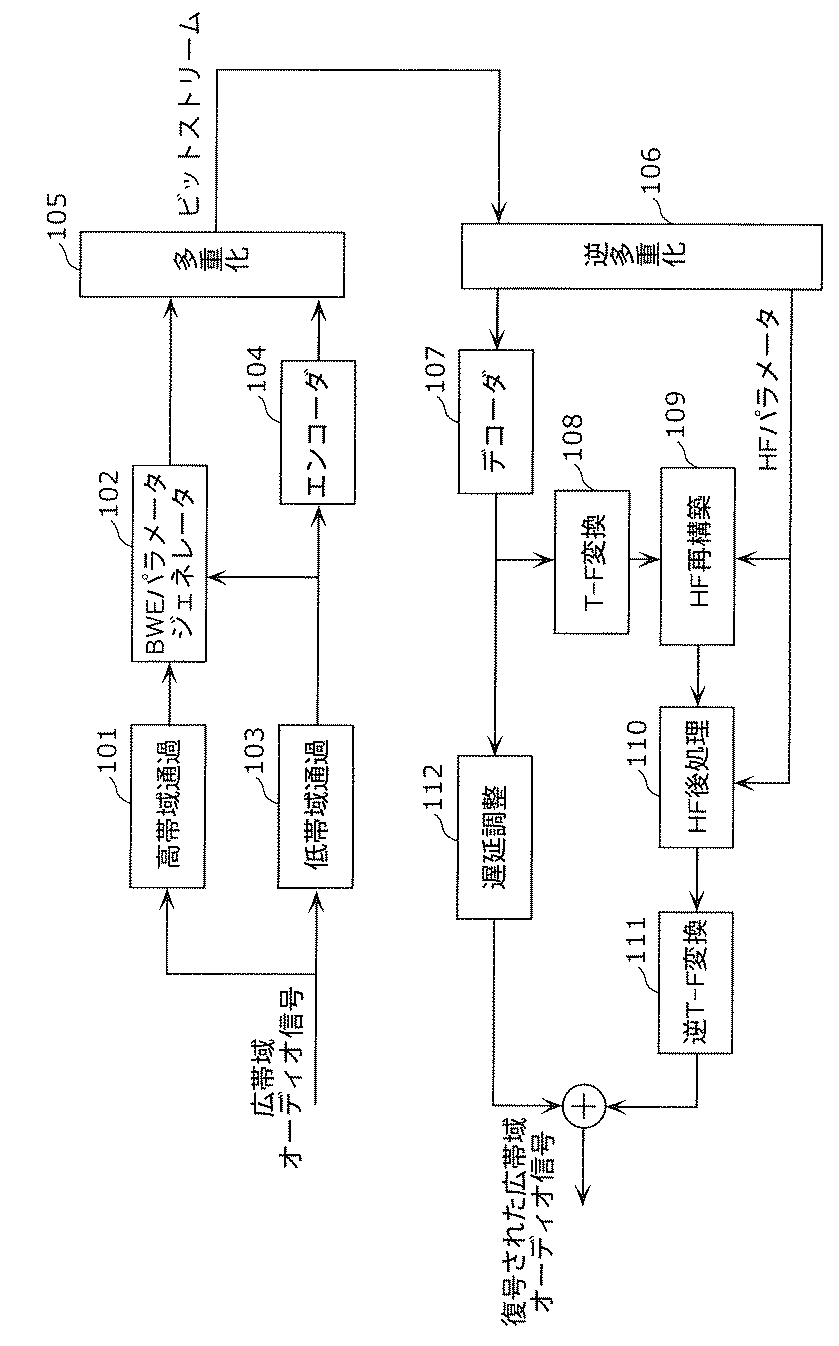
FIG. 1 is a diagram showing such a BWE technology-based audio codec. In the encoder of this audio codec, the wideband audio signal is first separated into an LF portion and an HF portion (101 and 103), and this LF portion is encoded so as to retain a waveform (104). On the other hand, the relationship between the LF and HF parts is analyzed (generally in the frequency domain) (102) and indicated by a set of HF parameters. By indicating the HF portion as a parameter, the multiplexed (105) waveform data and the HF parameter can be transmitted to the decoder at a low bit rate.
In the decoder, the LF part is first decoded (107). To approximate the original HF portion, the decoded LF portion is converted to the frequency domain (108), the resulting LF spectrum is modified according to some decoded HF parameters (109), and the HF spectrum is Will be generated. The HF spectrum is also further refined by post-processing according to some decoded HF parameters (110). The refined HF spectrum is converted into the time domain (111) and combined with the delayed (112) LF portion. As a result, the reconstructed final wideband audio signal is output.
In BWE technology, one of the important steps is to generate the HF spectrum from the LF spectrum (109). There are several ways to achieve this, such as copying the LF portion to the HF position, non-linear processing, or upsampling.
The most well-known audio codec that uses such BWE technology is MPEG-4 HE-AAC, where BWE technology is defined as SBR (spectral band replication) or SBR technology. In SBR, the HF portion is generated by simply copying the LF portion in the QMF (quadrature mirror filter) display to the HF spectral position.
Such a spectral copying process, also called patching, has proven to be simple and often efficient. However, SBR technology at very low bit rates (eg <20kbits / s mono), where only a small LF partial band is feasible, produces unwanted audible artifacts such as roughness and unpleasant sound quality. It may bring about (see, for example, Non-Patent Document 1).
Therefore, in order to avoid the artifacts caused by mirroring or copying mentioned in the case of encoding at a low bit rate, the standard SBR technique has been improved and extended by the following major changes (eg, non-copying). See Patent Document 2).
(1) Change the patching algorithm from a copy pattern to a phase vocoder-driven patching pattern. (2) Increase the adaptive time resolution for post-processing parameters.
As a result of making the first change ((1) above), the continuity of harmonics in HF is essentially ensured by diffusing the LF spectrum with multiple integer coefficients. In particular, the undesired roughness caused by the effects of beats does not occur at the boundary between low and high frequencies and at the boundary between different high frequency parts (see, eg, Non-Patent Document 1).
The second change ((2) above) also makes it easier to make the refined HF spectrum more adaptable to signal fluctuations in the reproduced frequency band.
This is called Harmonics Bandwidth Extension (HBE) because the new patching retains the harmonics relationship. The effect of prior art HBE over standard SBR has also been confirmed experimentally for audio coding at low bit rates (see, for example, Non-Patent Document 1).
It should be noted that the above two changes affect only the HF spectrum generator (109), and the other methods in HBE are exactly the same as SBR.
FIG. 2 is a diagram showing an HF spectrum generator in the prior art HBE. The HF spectrum generator is composed of the TF conversion 108 and the HF reconstruction 109 shown in FIG. The LF part of a signal is input, and its HF spectrum has (T-1) HF harmonics patches (T-1) from the 2nd order (HF patch with the lowest frequency) to the Tth order (HF patch with the highest frequency). It is assumed that one HF patch is created in each patching process). In the prior art HBE, all of these HF patches are generated separately from the phase vocoder in parallel.
As shown in FIG. 2, (T-1) phase vocoders (201-203) with different stretch coefficients (2 to k) are used to stretch the input LF portion. The stretched outputs have different lengths, and these outputs are passed through a band filter (204-206) and resampled (207-209) to convert the time extension into a frequency extension. By doing so, an HF patch is generated. By setting the stretch factor to twice the resampling factor, the HF patch maintains the harmonic structure of the signal and is twice as long as the LF portion. All HF patches are then delayed adjusted (210-212) to compensate for various potential delays due in part to the resampling process. In the final step, all delay-tuned HF patches are added together and converted into the QMF region (213) to create the HF spectrum.
Looking at the above HF spectrum generator, it has a very large amount of calculation. What contributes to the amount of computation is mainly due to the time expansion process, which is a series of short-time Fourier transforms (STFT) and inverse short-time Fourier transforms (ISTFT) adopted in the phase vocoder, as well as It is realized by the subsequent QMF processing applied to the time-stretched HF portion.
The outline of the phase vocoder and QMF conversion is introduced below.
A phase vocoder is a well-known technique that realizes a time extension effect by using frequency domain conversion. In other words, it is a technique for correcting changes over time in a signal while maintaining the local spectral characteristics unchanged. The basic principle is as follows.
3A and 3B are diagrams showing the principle of time extension by a phase vocoder.
As shown in Figure 3A, the audio is divided into overlapping blocks and the intervals between blocks whose hop sizes (time intervals between consecutive blocks) are not the same at input and output are adjusted. Here, the input hop size R<sub>a</sub>Is the output hop size R<sub>s</sub>As a result, the original signal is extended by the ratio r shown in (Equation 1) below.
<maths num="1"><img id="000002" he="22" wi="68" file="JP5750464B2_D0001.tif" img-format="tif" img-content="drawing" /></maths>
As shown in FIG. 3B, the spaced blocks are superposed in a coherent pattern that requires frequency domain conversion. Generally, the input block is converted to frequency, the phase is corrected appropriately, and then the new block is converted to the original output block.
Following the above principles, most typical phase vocoders employ the Short Time Fourier Transform (STFT) as the frequency domain transform, which requires an explicit order of analysis, as well as modification and resynthesis for time extension. Is.
The QMF bank transforms the time domain display into a time-frequency domain coupled display (and vice versa), such as spectral band replication (SBR), parametric stereo coding (PS), and spatial audio coding (SAC). It is commonly used in parametric-based coding schemes. A feature of these filter banks is that complex frequency (subband) region signals are efficiently oversampled by a factor of 2. As a result, post-processing of the subband region signal can be performed without causing distortion due to aliasing.
More specifically, assuming that the real-valued discrete-time signal is x (n), the QMF bank analysis shows that the complex subband region signal s.<sub>k</sub>(n) is obtained by the following (Equation 2).
<maths num="2"><img id="000003" he="22" wi="154" file="JP5750464B2_D0001.tif" img-format="tif" img-content="drawing" /></maths>
In (Equation 2), p (n) indicates the impulse response of the L-1st-order low-pass prototype filter, α indicates the phase parameter, M indicates the number of bands, and k indicates the subband index. k = 0, 1, ..., M-1.
Similar to STFT, QMF conversion is also time-frequency coupling conversion. That is, this allows both the frequency content of the signal and the change over time in the frequency content to be obtained, where the frequency content is indicated by the frequency subband and the time axis is indicated by the time slot.
FIG. 4 is a diagram showing a QMF analysis and synthesis method.
Specifically, as shown in Figure 4, an actual voice input is divided into consecutive, overlapping blocks of length L and hop size M ((a) in Figure 4), QMF. By the analysis process, each block is converted into one time slot, and each time slot is composed of M complex subband signals. By this method, the L time domain input sample is converted into L complex QMF coefficients, which are composed of L / M time slots and M subbands (Fig. 4 (b)). Each time slot is combined with a preceding (L / M-1) time slot and combined by a QMF synthesis process to almost perfectly reconstruct M real-time region samples ((c) in Figure 4). ..
<p num="0031"><nplcit num="1"><text>Frederik Nagel and Sascha Disch, "A harmonic bandwidth extension method for audio codecs", IEEE Int.Conf.on Acoustics, Speech and Signal Proc., 2009</text></nplcit><nplcit num="2"><text>Max Neuendorf, et al, "A novel scheme for low bitrate unified speech and audio coding-MPEG RM0", 126th AES Convention, Munich, Germany, May 2009</text></nplcit></p>
<p num="0032"> The problem associated with the HBE technology, which is the prior art, is that the amount of calculation is large. The traditional phase vocoder adopted by HBE to stretch the signal is computationally intensive because it applies continuous STFT and ISTFT, namely continuous FFT (Fast Fourier Transform) and IFFT (Inverse Fast Fourier Transform). Subsequent QMF transforms are applied to the time stretch signal, which increases the amount of computation. Further, in general, if an attempt is made to reduce the amount of calculation, quality may be deteriorated.</p><p num="0033"> Therefore, the present invention has been made in view of such a problem, and an object of the present invention is to provide a band expansion method capable of reducing the amount of calculation for band expansion and suppressing the deterioration of the quality of the band to be expanded. To do.</p>
<p num="0034"><u style="single">In order to achieve the above object, the band expansion method according to one aspect of the present invention is a band expansion method for generating an entire band signal from a low frequency band signal, and the low frequency band signal is converted into a quadrature mirror filter bank (QMF). A first conversion step that produces a first low frequency QMF spectrum by converting to a region) and a second conversion step that causes the low frequency band signal to have a higher frequency resolution than the first low frequency QMF spectrum. A low-order harmonics patch generation step that generates a low-order harmonics patch by time-extending the low-frequency band signal by converting to a low-frequency QMF spectrum, and applying different shift coefficients to the low-order harmonics patches. Thereby, the high frequency generation step of generating a plurality of pitch-shifted signals and generating a high frequency QMF spectrum from the plurality of signals, the high frequency QMF spectrum, and the first low frequency QMF spectrum are combined. The high frequency generation step includes a decomposition step for dividing each QMF subband in the plurality of signals into a plurality of sub-subbands, and the plurality of sub-subbands. Includes a mapping step that maps the subbands to multiple high frequency QMF subbands.</u><u style="single"> Also,</u>In order to achieve the above object, the band expansion method according to one aspect of the present invention is a band expansion method for generating an entire band signal from a low frequency band signal, and the low frequency band signal is converted into a quadrature mirror filter bank (QMF). A first conversion step that generates a first low-frequency QMF spectrum by converting to a region), and a plurality of pitch-shifted signals by applying different shift coefficients to the low-frequency band signals. The high frequency is satisfied with the pitch shift step to be generated, the high frequency generation step to generate a high frequency QMF spectrum by time-extending the plurality of pitch-shifted signals in the QMF region, and the high frequency energy and tone. It includes a spectrum correction step for modifying the QMF spectrum and an all-band generation step for generating the full-band signal by combining the modified high-frequency QMF spectrum with the first low-frequency QMF spectrum.</p><p num="0035"> As a result, a plurality of pitch-shifted signals are time-stretched in the QMF region to generate a high-frequency QMF spectrum. Therefore, in order to generate a high-frequency QMF spectrum, it is possible to avoid the conventional complicated processing (continuously repeated FFT and IFFT and subsequent QMF transform), and reduce the amount of bandwidth expansion calculation. it can. Note that, like the STFT, the QMF transform itself provides a time-frequency coupling resolution, so the QMF transform replaces a series of STFTs and ISTFTs. Further, in the band expansion method according to one aspect of the present invention, by applying not only one shift coefficient but also different shift coefficients from each other, a plurality of pitch-shifted signals are generated, and a plurality of pitch-shifted signals are generated with respect to these. Since the stretching is performed, the deterioration of the quality of the high frequency QMF spectrum can be suppressed.</p><p num="0036"> Further, the high frequency generation step includes a second conversion step of generating a plurality of QMF spectra by converting the plurality of pitch-shifted signals into a QMF region, and a plurality of different QMF spectra. The harmonics patch generation step of generating a plurality of harmonics patches by stretching in the time dimension direction with the expansion coefficient of, the adjustment step of adjusting the time of the plurality of harmonics patches, and the time-adjusted harmonics patches are added up. Includes summing steps.</p><p num="0037"> Further, the harmonics patch generation step includes a calculation step of calculating the amplitude and phase of the QMF spectrum, a phase manipulation step of generating a new phase by manipulating the phase, and the amplitude and the new phase. Includes a QMF coefficient generation step that, when combined, generates a new set of QMF coefficients.</p><p num="0038"> Also, in the phase manipulation step, the new phase is generated based on the original phase of the entire set of QMF coefficients.</p><p num="0039"> Further, in the phase operation step, the operation is repeated for the set of QMF coefficients, and in the QMF coefficient generation step, a plurality of new sets of QMF coefficients are generated.</p><p num="0040"> Further, in the phase operation step, different operations are performed depending on the QMF subband index.</p><p num="0041"> Further, in the QMF coefficient generation step, the QMF coefficient corresponding to the time-extended audio signal is generated by overlapping addition of a plurality of the new QMF coefficient sets.</p><p num="0042"> That is, in the time expansion in the band expansion method according to one aspect of the present invention, the STFT-based expansion method is performed by correcting the phase of the input QMF block and overlapping the corrected QMF blocks with different hop sizes. Is imitating. Comparing such a time stretch with the continuous FFT and IFFT in the STFT-based method from the viewpoint of the amount of calculation, the amount of calculation is small in this time stretch because the QMF analysis conversion is performed only once. Therefore, the amount of calculation for bandwidth expansion can be further reduced.</p><p num="0043"> Further, in order to achieve the above object, the band expansion method according to another aspect of the present invention is a band expansion method for generating an entire band signal from a low frequency band signal, and the low frequency band signal is quadrature mirror filter. A first conversion step to generate a first low frequency QMF spectrum by converting to a bank (QMF) region and a low order harmonics patch generated by time stretching the low frequency band signal in the QMF region. By applying different shift coefficients to the low-order harmonics patch generation step and the low-order harmonics patch, a plurality of pitch-shifted signals are generated, and a high-frequency QMF spectrum is generated from the plurality of signals. By combining the generation step, the spectrum correction step of modifying the high frequency QMF spectrum so as to satisfy the high frequency energy and tone conditions, the modified high frequency QMF spectrum, and the first low frequency QMF spectrum. The full-band generation step of generating the full-band signal is included.</p><p num="0044"> As a result, the low frequency band signal is time-stretched and pitch-shifted in the QMF region to generate a high frequency QMF spectrum. Therefore, in order to generate a high-frequency QMF spectrum, it is possible to avoid complicated processing (FFT and IFFT that are continuously repeated and subsequent QMF transform), and it is possible to reduce the amount of calculation. Furthermore, by applying not only one shift coefficient but also different shift coefficients from each other, a plurality of pitch-shifted signals are generated, and a high-frequency QMF spectrum is generated from these signals. Deterioration of quality can be suppressed. Moreover, since the high frequency QMF spectrum is generated from the low-order harmonics patch, the deterioration of the quality can be further suppressed.</p><p num="0045"> In the band expansion method according to another aspect of the present invention, pitch shifting is also performed in the QMF region. This is to break down the LF QMF subbands of the lower patch into multiple sub-subbands for high frequency resolution, and then map these sub-subbands to the higher-order QMF subbands. To generate a higher-order patch spectrum.</p><p num="0046"> Further, the low-order harmonics patch generation step includes a second conversion step of converting the low-frequency band signal into a second low-frequency QMF spectrum, and a band-passing step of passing the second low-frequency QMF spectrum through the band. Includes an extension step that extends the banded second low frequency QMF spectrum in the time dimension direction.</p><p num="0047"> Further, the second low frequency QMF spectrum has a higher frequency resolution than the first low frequency QMF spectrum.</p><p num="0048"> Further, in the high frequency generation step, a patch generation step for generating a plurality of band-passed patches by passing the low-order harmonics patch through the band and a patch generation step for generating the plurality of band-passed patches are mapped to high frequencies, respectively. It includes a higher-order generation step of generating a plurality of higher-order harmonics patches, and a totaling step of adding the plurality of higher-order harmonics patches to the lower-order harmonics patches.</p><p num="0049"> Further, the higher-order generation step is a decomposition step of dividing each QMF subband in the patch passed through the band into a plurality of sub-subbands, and a mapping of mapping the plurality of sub-subbands to a plurality of high-frequency QMF subbands. The step includes a combination step that combines the mapping results of the plurality of sub-subbands.</p><p num="0050"> Further, the mapping step includes a division step of dividing the plurality of sub-subbands of the QMF subband into a blocking band portion and a passband portion, and a rearrangement of the plurality of sub-subbands on the passband portion. A frequency calculation step of calculating the center frequency with a coefficient depending on the order of the patch, and a first mapping of a plurality of sub-subbands on the passband portion to a plurality of high-frequency QMF subbands according to the center frequency. The mapping step of is included, and a second mapping step of mapping the plurality of sub-subbands on the blocking band portion to the high frequency QMF subband according to the plurality of sub-subbands on the passband portion.</p><p num="0051"> In the band expansion method according to the present invention, the above-mentioned processing operations (steps) may be combined in any way.</p><p num="0052"> Such a band expansion method according to the present invention is a low calculation amount HBE technique using an HF spectrum generator with a reduced calculation amount. The HF spectrum generator is the number one factor contributing to the computational complexity of HBE technology. In order to reduce this calculation amount, the band expansion method according to one aspect of the present invention uses a new QMF-based phase vocoder that extends the time in the QMF region with a low calculation amount. In addition, the bandwidth expansion method according to another aspect of the present invention generates high-order harmonics patches from low-order patches in the QMF region in order to avoid quality problems that may accompany this solution. Use a new pitch shift algorithm.</p><p num="0053"> An object of the present invention is to design a QMF-based patch that is capable of time-stretching, or both time-stretching and frequency-stretching, in the QMF region, and is thereby driven by a QMF-based phase vocoder. It is to develop a low arithmetic HBE technology.</p><p num="0054"> The present invention can be realized not only as such a band expansion method, but also a band expansion device for expanding the frequency band of an audio signal by the band expansion method, an integrated circuit, and a frequency band in a computer by the band expansion method. It can also be realized as a program for expanding the frequency and a storage medium for storing the program.</p>
<p num="0055"> The bandwidth expansion method of the present invention is for designing a new harmonics bandwidth expansion (HBE) technology. The core of this technique is to perform time-stretching, or both time-stretching and pitch-shifting, in the QMF domain rather than in the conventional FFT or time domain. Compared with the HBE technique of the prior art, the band expansion method of the present invention can obtain good sound quality and significantly reduce the amount of calculation.</p>
<figref num="1">FIG. 1 is a diagram showing an audio codec system using ordinary BWE technology.</figref><figref num="2">FIG. 2 is a diagram showing an HF spectrum generator that retains a harmonic structure.</figref><figref num="3A">FIG. 3A is a diagram showing the principle of time extension by adjusting the interval of audio blocks.</figref><figref num="3B">FIG. 3B is a diagram showing the principle of time extension by adjusting the interval of audio blocks.</figref><figref num="4">FIG. 4 is a diagram showing a QMF analysis and synthesis method.</figref><figref num="5">FIG. 5 is a flowchart showing a band expansion method according to the first embodiment of the present invention.</figref><figref num="6">FIG. 6 is a diagram showing an HF spectrum generator according to the first embodiment of the present invention.</figref><figref num="7">FIG. 7 is a diagram showing an audio decoder according to the first embodiment of the present invention.</figref><figref num="8">FIG. 8 is a diagram showing a signal timescale changing method based on the QMF conversion according to the first embodiment of the present invention.</figref><figref num="9">FIG. 9 is a diagram showing a time extension method in the QMF region according to the first embodiment of the present invention.</figref><figref num="10">FIG. 10 is a diagram showing a comparison of the stretching effects of sinusoidal tone signals using different stretching coefficients.</figref><figref num="11">FIG. 11 is a diagram showing the arrangement shift and the energy diffusion effect in the HBE method.</figref><figref num="12">FIG. 12 is a flowchart showing a band expansion method according to the second embodiment of the present invention.</figref><figref num="13">FIG. 13 is a diagram showing an HF spectrum generator according to the second embodiment of the present invention.</figref><figref num="14">FIG. 14 is a diagram showing an audio decoder according to the second embodiment of the present invention.</figref><figref num="15">FIG. 15 is a diagram showing a frequency expansion method in the QMF region according to the second embodiment of the present invention.</figref><figref num="16">FIG. 16 is a diagram showing a sub-subband spectrum distribution according to the second embodiment of the present invention.</figref><figref num="17">FIG. 17 is a diagram showing a relationship between a passband component for a sine wave and a blocking band component in the complex QMF region according to the second embodiment of the present invention.</figref>
The following forms merely illustrate the principles of the various invention steps. Various variations of the specific examples described herein will be apparent to those skilled in the art.
(Embodiment 1) Hereinafter, the HBE method (harmonics band expansion method) of the present invention and a decoder (audio decoder or audio decoding device) using the method will be described.
FIG. 5 is a flowchart showing a bandwidth expansion method according to the present embodiment.
This band expansion method is a band expansion method for generating an entire band signal from a low frequency band signal, and is a first low frequency QMF by converting the low frequency band signal into a quadrature mirror filter bank (QMF) region. A first conversion step (S11) for generating a spectrum, a pitch shift step (S12) for generating a plurality of pitch-shifted signals by applying different shift coefficients to the low frequency band signals, and a pitch. The high-frequency QMF spectrum is modified so as to satisfy the high-frequency generation step (S13) for generating the high-frequency QMF spectrum and the high-frequency energy and tone conditions by time-extending the plurality of shifted signals in the QMF region. The spectrum correction step (S14) includes a full-band generation step (S15) for generating the full-band signal by combining the modified high-frequency QMF spectrum with the first low-frequency QMF spectrum.
The first conversion step (S11) is performed by the TF conversion unit 1406 described later, and the pitch shift step (S12) is performed by the sampling units 504 to 506 and the time resampling unit 1403 described later. Further, the high frequency generation step (S13) is performed by the QMF conversion unit 507 to 509, the phase vocoder 510 to 512, the QMF conversion unit 1404, and the time extension unit 1405, which will be described later. Further, the spectrum correction step (S14) is performed by the HF processing unit 1408 described later, and the full band generation step (S15) is performed by the addition unit 1410 described later.
Further, the high frequency generation step includes a second conversion step of generating a plurality of QMF spectra by converting the plurality of pitch-shifted signals into a QMF region, and a plurality of different QMF spectra. The harmonics patch generation step of generating a plurality of harmonics patches by stretching in the time dimension direction with the expansion coefficient of, the adjustment step of adjusting the time of the plurality of harmonics patches, and the time-adjusted harmonics patches are added up. Includes summing steps.
The second conversion step is performed by the QMF conversion units 507 to 509 and the QMF conversion unit 1404, and the harmonics patch generation step is performed by the phase vocoder 510 to 512 and the time extension unit 1405. Further, the adjustment step is performed by the delay adjustment units 513 to 515 described later, and the summing step is performed by the addition unit 516 described later.
In the HBE method of the present embodiment, the HF spectrum generator in the HBE technology is designed by using pitch shifting processing in the time domain and vocoder-driven time stretching processing in the subsequent QMF region.
FIG. 6 is a diagram showing an HF spectrum generator used in the HBE method of the present embodiment. The HF spectrum generator includes band passage units 501, 502, ..., 503, sampling units 504, 505, ..., 506, QMF conversion units 507, 508, ..., 509, and phase vocoder 510, It includes 511, ..., 512, delay adjusting units 513, 514, ..., 515, and an adding unit 516.
The input of the given LF band is first passed through the band (501 to 503) and then resampled (504 to 506) to generate this HF band portion. These HF band portions are converted to the QMF region (507-509) and the resulting QMF output is time-stretched (510-512) with a corresponding stretch factor of twice the resampling factor. The stretched HF spectrum is delayed adjusted (513 to 515), compensating for various potential delays contributed by the spectrum transformation process and summing them together (516) to produce the final HF spectrum. The numbers 501-516 in parentheses indicate the components of the HF spectrum generator, respectively.
Comparing the method of this embodiment with the method of the prior art (Fig. 2), the main differences are as follows. 1) More QMF transforms are applied, 2) Time stretch processing is done in the QMF region instead of the FFT region. Further details of the time extension processing in the QMF region will be described later.
FIG. 7 is a diagram showing a decoder that employs the HF spectrum generator according to the present embodiment. This decoder (audio decoding device) includes a demultiplexing unit 1401, a decoding unit 1402, a time resampling unit 1403, a QMF conversion unit 1404, a time extension unit 1405, a TF conversion unit 1406, and a delay adjustment unit 1407. , HF post-processing unit 1408, addition unit 1410, and inverse TF conversion unit 1409. The HF spectrum generator is composed of a time resampling unit 1403, a QMF conversion unit 1404, and a time extension unit 1405. In the present embodiment, the demultiplexing unit 1401 corresponds to a separation unit that separates the encoded low frequency band signal from the coding information (bit stream). Further, the inverse TF conversion unit 1409 corresponds to an inverse conversion unit that converts a full-band signal from a signal in the quadrature mirror filter bank (QMF) region to a signal in the time domain.
In this decoder, the bitstream is first demultiplexed (1401) and then the LF portion of the signal is decoded (1402). In order to approximate the original HF part, the decoded LF part (low frequency band signal) is resampled in the time domain to generate the (1403) HF part, and the obtained HF part is converted into the QMF region. Be done (1404). The resulting HF QMF spectrum is stretched over time (1405) and the stretched HF spectrum is further refined by post-processing according to some decoded HF parameters (1408). On the other hand, the decoded LF part is also converted into the QMF area (1406). Finally, the refined HF spectrum is combined with the delayed (1407) LF spectrum (1410) to create a full-band QMF spectrum. The obtained QMF spectrum of the entire band is converted into the original time domain (1409), and the decoded wideband audio signal is output. The numbers 1401-1410 in parentheses indicate the components of the decoder.
Time extension method The HBE-type time extension processing of the present embodiment targets an audio signal, and the time extension signal can be generated by QMF conversion, phase manipulation, and inverse QMF conversion. That is, the harmonics patch generation step includes a calculation step for calculating the amplitude and phase of the QMF spectrum, a phase manipulation step for generating a new phase by manipulating the phase, and the amplitude and the new phase. Includes a QMF coefficient generation step that, when combined, generates a new set of QMF coefficients. The calculation step, the phase operation step, and the QMF coefficient generation step are performed by the module 702, which will be described later.
FIG. 8 is a diagram showing a QMF-based time expansion process by the QMF conversion unit 1404 and the time extension unit 1405. First, the audio signal is transformed by the QMF analytical transformation (701) into a set of QMF coefficients, eg X (m, n). These QMF coefficients are modified in module 702. Here, the amplitude r and the phase a of each QMF coefficient are calculated. For example, let X (m, n) = r (m, n) · exp (j · a (m, n)). This phase a (m, n) is modified (manipulated) to a ~ (m, n). The modified phase a ~ and the original amplitude r construct a new set of QMF coefficients. For example, a new set of QMF coefficients is given by (Equation 3) below.
<maths num="3"><img id="000004" he="16" wi="154" file="JP5750464B2_D0001.tif" img-format="tif" img-content="drawing" /></maths>
Finally, the new set of QMF coefficients is converted to a new audio signal that corresponds to the original timescale-corrected audio signal (703).
The QMF-based time stretching algorithm in the HBE method of this embodiment mimics the STFT-based stretching algorithm. That is, 1) the phase is corrected using the instantaneous frequency concept at this correction stage, and 2) overlap addition is performed in the QMF region using the additive characteristic of QMF conversion in order to reduce the amount of calculation. Is done.
The details of the time extension algorithm in the HBE method of the present embodiment are described below.
Assuming that there are 2 L real time domain signals x (n) stretched by the stretch factor s, after the QMF analysis stage, it is composed of 2 L / M time slots and M subbands. There are 2L QMF complex coefficients.
As with the STFT-based expansion method, the converted QMF coefficient may be subject to analysis window processing before the phase operation, if necessary. In the present invention, the above can be realized in either the time domain or the QMF domain.
In the time domain, the time domain signal is usually window-processed as follows (Equation 4).
<maths num="4"><img id="000005" he="16" wi="116" file="JP5750464B2_D0001.tif" img-format="tif" img-content="drawing" /></maths>
The mod (.) In (Equation 4) indicates the modulation process.
In the QMF area, it is possible to realize the same operation as follows.
1) The analysis window h (n) (having length L) is converted into a QMF region to obtain H (v, k) with L / M time slots and M subbands.
2) Simplify the QMF display of the window as shown in (Equation 5) below.
<maths num="5"><img id="000006" he="21" wi="116" file="JP5750464B2_D0001.tif" img-format="tif" img-content="drawing" /></maths>
Here, v = 0, ..., L / M-1.
3) Perform analysis window processing in the QMF area with X (m, k) = X (m, k) · H<sub>0</sub>It is performed by (w), and in the formula, w = mod (m, L / M) (note that mod (.) Indicates modulation processing).
Further, in the HBE method of the present embodiment, in the phase operation step, the new phase is generated based on the original phase of the entire set of QMF coefficients. That is, in the present embodiment, the phase operation is performed based on the QMF block as details regarding the realization of time extension.
FIG. 9 is a diagram showing a time extension method in the QMF region.
As shown in (a) of FIG. 9, the original QMF coefficient can be treated as L + 1 superposed QMF blocks, the hop size is 1 time slot, and the block length is L. / M time slot.
To ensure that the effects of phase jumps are eliminated, each original QMF block is modified to generate a new QMF block with the modified phase. The phase of the new QMF block should be continuous at the μ · s point with respect to the overlapping (μ) and (μ + 1) th new QMF blocks, which is μ · M in the time domain. It is equivalent to being continuous at the junction of s (μ N).
Further, in the HBE method of the present embodiment, in the phase operation step, the operation is repeated for the QMF coefficient set, and in the QMF coefficient generation step, a plurality of new QMF coefficient sets may be generated. Good. In this case, the phase is modified block by block according to the following criteria.
The original phase of the given QMF coefficient X (u, k) is φ<sub>u</sub>Assuming (k), u = 0, ···, 2L / M-1 and k = 0, 1, ···, M-1. Each of the original QMF blocks is sequentially modified to a new QMF block as shown in FIG. 9 (b), and in the same figure, the new QMF block is shown with a different fill pattern.
In the following, ψ<sub>u</sub><sup>(n)</sup>(k) shows the nth phase information of the new QMF block, n = 1, ···, L / M, u = 0, ··· L / M-1, and k = 0,1 , ..., M-1. These new phases are designed as follows, depending on whether the spacing between the new blocks has been adjusted.
The first new QMF block, X<sup>(1)</sup>It is assumed that the interval of (u, k) (u = 0, ... L / M-1) is not adjusted. Then, new phase information ψ<sub>u</sub><sup>(1)</sup>(k) is φ<sub>u</sub>Same as (k). That is, ψ<sub>u</sub><sup>(1)</sup>(k) = φ<sub>u</sub>(k), u = 0, ... L / M-1 and k = 0, 1, ..., M-1.
Second new QMF block, X<sup>(2)</sup>The intervals between (u, k) (u = 0, ... L / M-1) are adjusted by the hop size of the s time slot (for example, 2 time slots as shown in FIG. 9). In this case, the instantaneous frequency at the beginning of the block is the first new QMF block X<sup>(1)</sup>It should match the instantaneous frequency of the sth time slot of (u, k). Therefore, X<sup>(2)</sup>The instantaneous frequency of the first time slot in (u, k) should be the same as the instantaneous frequency of the second time slot in the original QMF block. That is, ψ<sub>0</sub><sup>(2)</sup>(k) = ψ<sub>0</sub><sup>(1)</sup>(k) + s Δφ<sub>1</sub>(k).
Also, since the phase of the first time slot is changed, the remaining phases are appropriately adjusted to retain the original instantaneous frequency. That is, ψ<sub>u</sub><sup>(2)</sup>(k) = ψ<sub>u-1</sub><sup>(2)</sup>(k) + Δφ<sub>u + 1</sub>(k), u = 1, ... L / M-1. In the formula, Δφ<sub>u</sub>(k) = φ<sub>u</sub>(k) -φ<sub>u-1</sub>(k) indicates the original instantaneous frequency of the original QMF block.
The same phase correction rules apply to subsequent composite blocks. That is, for the mth new QMF block (m = 3, ... L / M), its phase ψ<sub>u</sub><sup>(m)</sup>(k) is determined by the following equation.
ψ<sub>0</sub><sup>(m)</sup>(k) = ψ<sub>0</sub><sup>(m-1)</sup>(k) + s Δφ<sub>m-1</sub>(k) ψ<sub>u</sub><sup>(m)</sup>(k) = ψ<sub>u-1</sub><sup>(m)</sup>(k) + Δφ<sub>m + u-1</sub>(k), u = 1, ..., L / M-1.
Combined with the original block amplitude information, the above new phase becomes a new L / M block.
Here, in the HBE method of the present embodiment, in the phase operation step, different operations may be performed depending on the QMF subband index. That is, the phase correction method may be designed so as to be different for the odd-numbered subband and the even-numbered subband of the QMF.
This is based on the fact that the instantaneous frequency in the QMF region of the tone signal is associated with the phase difference Δφ (n, k) = φ (n, k) -φ (n-1, k) in different ways. There is.
More specifically, the instantaneous frequency ω (n, k) is obtained by the following (Equation 6).
<maths num="6"><img id="000007" he="14" wi="127" file="JP5750464B2_D0001.tif" img-format="tif" img-content="drawing" /></maths>
In (Equation 6), princarg (α) means the main angle α and is defined by the following (Equation 7).
<maths num="7"><img id="000008" he="13" wi="147" file="JP5750464B2_D0001.tif" img-format="tif" img-content="drawing" /></maths>
Mod (a, b) in the equation indicates the modulation of a with respect to b.
As a result, for example, in the above phase correction method, the phase difference is shown in detail by the following (Equation 8).
<maths num="8"><img id="000009" he="14" wi="123" file="JP5750464B2_D0001.tif" img-format="tif" img-content="drawing" /></maths>
Further, in the HBE method of the present embodiment, in the QMF coefficient generation step, the QMF coefficient corresponding to the time-extended audio signal is generated by overlapping addition of a plurality of the new QMF coefficient sets. That is, in order to reduce the amount of calculation, the QMF composition process is not directly applied to each new QMF block, but is applied to the result of overlapping addition of these new QMF blocks.
As with the STFT-based extension method, the new QMF coefficient is subject to composite window processing, if necessary, before overlap addition. In the present embodiment, the composite window processing can be realized by the following like the analysis window processing.
X<sup>(n + 1)</sup>(u, k) = X<sup>(n + 1)</sup>(u, k) H<sub>0</sub>It is (w), and w = mod (u, L / M) in the equation.
And because the QMF conversion is additive, all new L / M blocks can be overlapped and added at the hop size of the s time slot before QMF synthesis. Y (u, k), which is the result of overlap addition, is calculated by the following equation.
<maths num="9"><img id="000010" he="16" wi="153" file="JP5750464B2_D0001.tif" img-format="tif" img-content="drawing" /></maths>
n = 0, ···, L / M-1, u = 1, ··· L / M, and k = 0, 1, ···, M-1.
The final audio signal can be generated by applying QMF synthesis to Y (u, k), which corresponds to the modified timescale.
Comparing the QMF-based decompression method in the HBE method of the present embodiment with the STFT-based decompression method of the prior art, it is noted that the time resolution essential for the QMF conversion helps to significantly reduce the amount of calculation. Should be. This can only be obtained by performing a series of STFT transforms in the prior art STFT-based decompression method.
The following analysis of the amount of calculation shows a rough comparison result of the amount of calculation, and here, only the amount of calculation by conversion is considered.
The calculation amount of STFT of size L is log<sub>2</sub>Assuming that (L) and L, and the calculation amount of the QMF analysis conversion is about twice that of the FFT conversion, the conversion calculation amount associated with the HF spectrum generator of the prior art is approximated as follows.
<maths num="10"><img id="000011" he="13" wi="148" file="JP5750464B2_D0001.tif" img-format="tif" img-content="drawing" /></maths>
By comparison, the amount of conversion calculation associated with the HF spectrum generator of this embodiment is approximated as shown in (Equation 11) below.
<maths num="11"><img id="000012" he="23" wi="159" file="JP5750464B2_D0001.tif" img-format="tif" img-content="drawing" /></maths>
For example, assuming L = 1024 and Ra = 128, the above arithmetic comparison is specifically shown in Table 1.
<tables num="1"><img id="000013" he="39" wi="159" file="JP5750464B2_D0001.tif" img-format="tif" img-content="drawing" /></tables>
(Embodiment 2) Hereinafter, a second embodiment of the HBE method (harmonics band expansion method) and a decoder (audio decoder or audio decoding device) using the second embodiment will be described in detail.
When the QMF-based time extension method is adopted, the amount of calculation of the HBE technology in the QMF-based time extension method is significantly reduced. However, on the other hand, adopting a QMF-based time-stretching method can also cause two problems that can reduce sound quality.
First, higher-order patches have the problem of poor sound quality. It is assumed that the HF spectrum consists of (T-1) patches and the corresponding extension coefficients are 2, 3, ..., T. Since the QMF-based time extension is block-based, the extension effect decreases as the number of overlap addition processes decreases in higher-order patches.
FIG. 10 is a diagram showing the stretching effect of the sinusoidal tone signal. The upper frame (a) shows the stretching effect of the second patch of a pure sinusoidal tone signal. The stretched output is basically clean, with only a few other frequency components at small amplitudes. On the other hand, the lower frame (b) shows the stretching effect of the fourth patch of the same sinusoidal tone signal.
Compared to (a), in (b) the center frequency is correctly shifted, but the resulting output also contains some other frequency components with non-negligible amplitudes. This can result in unwanted noise at the stretched output.
Second, transient signal can have quality degradation problems. There are three potential contributors to this quality degradation problem.
The first contributor may be that transient components are lost during the resampling process. Assuming a transient signal with Dirac impulses located in even samples, the Dirac impulses disappear in the resampled signal in the 4th patch with a factor 2 decimation. The resulting HF spectrum has incomplete transient components.
The second contributor is the unadjusted transients in different patches. Because these patches have different resampling coefficients, a Dirac impulse located at a particular location may have several components located at different time slots in the QMF region.
FIG. 11 is a diagram showing the misalignment and the energy diffusion effect as problems of quality deterioration. After resampling an input with a Dirac impulse (eg, illustrated as a gray third sample in FIG. 11) with different coefficients, its position is changed to a different position. As a result, the stretched output is perceptually attenuated in transient effects.
The third contributor is that the energy of the transient components is unevenly diffused in different patches. As shown in FIG. 11, in the second patch, the associated transient components are diffused to the 5th and 6th samples. In the 3rd patch, it is spread to the 4th to 6th samples, and in the 4th patch, it is spread to the 5th to 8th samples. As a result, the transient effect of the stretched output is weakened at high frequencies. For some critical transient signals, unpleasant pre-echo and even post-echo artifacts appear at the stretched output.
In order to overcome the above-mentioned quality deterioration problem, advanced HBE technology is desirable. However, a solution that is too complex also increases the amount of computation. In this embodiment, a QMF-based pitch shifting method is used in order to avoid the expected quality deterioration problem and maintain the effect of low calculation amount.
In the HBE method (harmonics band expansion method) of the present embodiment, as described in detail below, the HF spectrum generator in the HBE technology of the present embodiment has both time stretching and pitch shifting processing in the QMF region. Designed using. Further, a decoder (audio decoder or audio decoding device) using the HBE method of the present embodiment will also be described below.
FIG. 12 is a flowchart showing a low arithmetic bandwidth expansion method according to the present embodiment.
This band expansion method is a band expansion method for generating an entire band signal from a low frequency band signal, and is a first low frequency QMF by converting the low frequency band signal into a quadrature mirror filter bank (QMF) region. A first conversion step (S21) for generating a spectrum, a low-order harmonics patch generation step (S22) for generating a low-order harmonics patch by time-extending the low-frequency band signal in the QMF region, and the low-order harmonics patch generation step (S22). A high-frequency generation step (S23) that generates a plurality of pitch-shifted signals by applying different shift coefficients to the next harmonics patch and generates a high-frequency QMF spectrum from the plurality of signals, and the high-frequency energy and The full-band signal is obtained by combining the spectrum correction step (S24) for modifying the high-frequency QMF spectrum so as to satisfy the tone condition, the modified high-frequency QMF spectrum, and the first low-frequency QMF spectrum. Includes a full band generation step (S25) to generate.
The first conversion step is performed by the TF conversion unit 1508 described later, and the low-order harmonics patch generation step is performed by the QMF conversion unit 1503, the time extension unit 1504, the QMF conversion unit 601 and the phase vocoder 603 described later. .. Further, the high frequency generation step is performed by the pitch shift unit 1506, the band passage unit 604,605, the frequency expansion unit 606,607, and the delay adjustment unit 608 to 610, which will be described later. Further, the spectrum correction step is performed by the HF post-processing unit 1507 described later, and the entire band generation step is performed by the addition unit 1512 described later.
Further, the low-order harmonics patch generation step includes a second conversion step of converting the low-frequency band signal into a second low-frequency QMF spectrum, and a band-passing step of passing the second low-frequency QMF spectrum through the band. Includes an extension step that extends the banded second low frequency QMF spectrum in the time dimension direction.
The second conversion step is performed by the QMF conversion unit 601 and the QMF conversion unit 1503, the band passage step is performed by the band passage unit 602 described later, and the expansion step is performed by the phase vocoder 603 and the time expansion unit 1504. Will be done.
Further, the second low frequency QMF spectrum has a higher frequency resolution than the first low frequency QMF spectrum.
Further, in the high frequency generation step, a patch generation step for generating a plurality of band-passed patches by passing the low-order harmonics patch through the band and a patch generation step for generating the plurality of band-passed patches are mapped to high frequencies, respectively. It includes a higher-order generation step of generating a plurality of higher-order harmonics patches, and a totaling step of adding the plurality of higher-order harmonics patches to the lower-order harmonics patches.
The patch generation step is performed by the band passing unit 604,605, the higher-order generation step is performed by the frequency expansion unit 606,607, and the summing step is performed by the addition unit 611 described later.
FIG. 13 is a diagram showing an HF spectrum generator used in the HBE method of the present embodiment. The HF spectrum generator includes a QMF conversion unit 601, a band passage unit 602, 604, ..., 605, a phase vocoder 603, a frequency expansion unit 606, ..., 607, and a delay adjustment unit 608, 609, ... ..., 610 and an addition unit 611 are provided.
The input in the given LF band is first converted to the QMF region (601), and the (602) QMF spectrum passed through that band is time-extended to twice the length (603). The stretched QMF spectrum is band-passed (604-605) to create band-limited (T-2) spectra. The resulting multiple band-limited spectra are converted to higher frequency band spectra (606-607). These HF spectra are delayed adjusted (608-610), compensating for the various potential delays contributed by the spectral transformation process and summing them together to produce the final HF spectrum (611). The numbers 601-611 in parentheses indicate the components of the HF spectrum generator.
Compared with the QMF conversion (108 in FIG. 1), the QMF conversion (QMF conversion unit 601) in the HBE method of the present embodiment has a higher frequency resolution, and the reduced time resolution is subsequently followed. Compensated by the stretching process of.
Comparing the HBE method of the present embodiment with the method of the prior art (Fig. 2), the main differences are as follows. 1) As in the first embodiment, the time stretching process is performed in the QMF region instead of the FFT region. 2) Higher-order patches are generated based on the second patch. 3) Pitch shifting processing is also performed in the QMF area, not in the time domain.
FIG. 14 is a diagram showing a decoder that employs the HF spectrum generator in the HBE system of the present embodiment. This decoder (audio decoding device) includes a demultiplexing unit 1501, a decoding unit 1502, a QMF conversion unit 1503, a time extension unit 1504, a delay adjustment unit 1505, a pitch shift unit 1506, and an HF post-processing unit 1507. A TF conversion unit 1508, a delay adjustment unit 1509, an inverse TF conversion unit 1510, and addition units 1511 and 1512 are provided. The HF spectrum generator is composed of a QMF conversion unit 1503, a time extension unit 1504, a delay adjustment unit 1505, a pitch shift unit 1506, and an addition unit 1511. In the present embodiment, the demultiplexing unit 1501 corresponds to a separation unit that separates the encoded low frequency band signal from the coding information (bit stream). Further, the inverse TF conversion unit 1510 corresponds to an inverse conversion unit that converts a full-band signal from a signal in the quadrature mirror filter bank (QMF) region to a signal in the time domain.
In this decoder, the bitstream is first demultiplexed (1501) and then the LF portion of the signal is decoded (1502). To approximate the original HF portion, the decoded LF portion (low frequency band signal) is transformed in the QMF region to produce the (1503) LF QMF spectrum. The LF obtained by this The QMF spectrum is stretched over time (1504) to produce lower order HF patches. The low-order HF patch is pitch-shifted (1506) to produce a high-order patch. The resulting higher-order patch is combined with a delayed (1505) lower-order HF patch to produce an HF spectrum. This HF spectrum is further refined by post-processing according to some decoded HF parameters (1507). On the other hand, the decoded LF part is also converted to the QMF area (1508). Finally, the refined HF spectrum is combined with the delayed (1509) LF spectrum to create a full-band QMF spectrum (1512). The obtained QMF spectrum of the entire band is converted into the original time domain (1510), and the decoded wideband audio signal is output. The numbers 1501-1512 in parentheses indicate the components of the decoder.
Pitch shift method The QMF-based pitch-shifting algorithm (frequency expansion method in the QMF region) in the HBE-type pitch-shifting unit 1506 of the present embodiment decomposes the LF QMF subband into a plurality of sub-subbands, and these sub-subbands are decomposed into a plurality of sub-subbands. Is transposed into an HF subband, and the obtained HF subbands are combined to generate an HF spectrum. That is, the higher-order generation step is a decomposition step that divides each QMF subband in the patch passed through the band into a plurality of sub-subbands, and a mapping that maps the plurality of sub-subbands to a plurality of high-frequency QMF subbands. The step includes a combination step that combines the mapping results of the plurality of sub-subbands.
The disassembly step corresponds to step 1 (901 to 903) described later, the mapping step corresponds to steps 2 and 3 (904 to 909) described later, and the combination step corresponds to step 4 (910) described later. ..
FIG. 15 is a diagram showing such a QMF-based pitch shifting algorithm. Given the band-passed spectrum of the second patch, the HF spectrum of the tth (t> 2) patch can be reconstructed by the following procedure. 1) Decompose the LF spectrum, that is, each QMF subband in the LF spectrum into multiple QMF sub-subbands (steps 1: 901 to 903), and 2) factor the center frequencies of these sub-subbands into coefficients t / Scale by 2 (step 2: 904 ~ 906), 3) map these sub-subbands to HF subbands (step 3: 907 ~ 909), 4) add up all mapped sub-subbands To form the HF subband (step 4: 910).
For step 1, there are several methods available for decomposing the QMF subband into multiple sub-subbands for better frequency resolution. For example, there is a so-called Mth band filter used in MPEG surround codecs. In a preferred embodiment of the invention, subband decomposition is achieved by applying an additional set of exponential modulation filter banks as defined by (Equation 12) below.
<maths num="12"><img id="000014" he="15" wi="159" file="JP5750464B2_D0001.tif" img-format="tif" img-content="drawing" /></maths>
Here, q = -Q, -Q + 1, ..., 0, 1, ..., Q-1, and n = 0, 1, ... N. (In the formula, n<sub>0</sub>Is an integer constant and N is the order of the filter bank. )
By adopting the above filter bank, a certain subband signal, for example, the kth subband signal x (n, k), is decomposed into 2Q sub-subband signals as shown in (Equation 13) below. Will be done.
<maths num="13"><img id="000015" he="15" wi="158" file="JP5750464B2_D0001.tif" img-format="tif" img-content="drawing" /></maths>
Here, q = -Q, -Q + 1, ..., 0, 1, ..., Q-1. In (Equation 13), "conv (.)" Indicates a convolution function.
With such an additional complex transformation, the frequency spectrum of one subband is further divided into 2Q subfrequency spectrum. From the viewpoint of frequency resolution, if there are M bands in the QMF conversion, the subband frequency resolution associated with this is π / M, and this sub-subband frequency resolution is π / (2Q · M). ). In addition, the entire system shown in (Equation 14) below is time-invariant, that is, aliasing does not occur even if downsampling and upsampling are used.
<maths num="14"><img id="000016" he="23" wi="90" file="JP5750464B2_D0001.tif" img-format="tif" img-content="drawing" /></maths>
It should be noted that the above additional filter banks are stacked in odd numbers (coefficient q + 0.5), which means that there are no sub-sub bands centered on the DC value. More precisely, when Q is even, the center frequencies of the sub-sub bands are symmetrically distributed around zero.
FIG. 16 is a diagram showing a sub-sub band spectral distribution. Specifically, FIG. 16 shows the spectral distribution of the filter bank in the case of Q = 6. The purpose of stacking with odd numbers is to facilitate later sub-subband combinations.
For step 2, center frequency scaling can be simplified by considering the oversampling feature of the complex QMF transformation.
In the complex QMF region, since the pass bands of adjacent subbands overlap each other, the frequency components in the overlapping range appear in both subbands (see Patent Document: WO2006048814).
As a result, frequency scaling can halve the amount of computation by calculating frequencies only for the sub-sub bands present in these passbands. That is, only the positive frequency portion is calculated for the even subband, or only the negative frequency portion is calculated for the odd subband.
More specifically, k<sub>LF</sub>The second subband is divided into 2Q subsubbands. That is, x (n, k<sub>LF</sub>) Is divided into the following (Equation 15).
<maths num="15"><img id="000017" he="14" wi="90" file="JP5750464B2_D0001.tif" img-format="tif" img-content="drawing" /></maths>
Then, in order to generate the t-th order patch, the center frequencies of these sub-sub bands are scaled by the following (Equation 16).
<maths num="16"><img id="000018" he="24" wi="159" file="JP5750464B2_D0001.tif" img-format="tif" img-content="drawing" /></maths>
k<sub>LF</sub>If is odd, q = -Q, -Q + 1, ..., -1, and k<sub>LF</sub>When is an even number, q = 0, 1, ..., Q-1.
For step 3, it is also necessary to consider the characteristics of the complex QMF transformation in order to map the sub-subbands to the HF subbands. In the present embodiment, such a mapping process is performed in two steps. The first step simply maps all sub-subbands on the passband to HF subbands, and the second step HF all sub-subbands on the stopband based on the mapping results above. Map to subband. That is, the mapping step is a division step that divides the plurality of sub-subbands of the QMF subband into a blocking band portion and a passband portion, and a rearrangement of the plurality of sub-subbands on the passband portion. A frequency calculation step of calculating the center frequency with a coefficient depending on the order of the patch, and a first mapping of a plurality of sub-subbands on the passband portion to a plurality of high-frequency QMF subbands according to the center frequency. The mapping step of is included, and a second mapping step of mapping the plurality of sub-subbands on the blocking band portion to the high frequency QMF subband according to the plurality of sub-subbands on the passband portion.
To understand the above points, it is useful to consider what kind of relationship exists between a pair of positive and negative frequencies of the same signal component, and the subband exponents associated with them. ..
As mentioned above, in the complex QMF region, the sinusoidal spectrum has both positive and negative frequencies. That is, the sinusoidal spectrum has one of them in the passband of one QMF subband and the other frequency in the blocking band of the adjacent subband. Considering that the QMF conversion is an odd stack conversion, such a signal component pair can be shown in FIG.
FIG. 17 is a diagram showing the relationship between the passband component and the blocking band component for a sine wave in the complex QMF region.
Here, the gray area indicates the blocking band of the subband. For any sinusoidal signal (shown by a solid line) on the passband of a subband, this aliasing portion (shown by a broken line) is located in the blocking band of an adjacent subband (two paired frequency components are double-headed arrows). Associated with).
The sine wave signal has the frequency f shown in (Equation 17) below.<sub>0</sub>Have.
<maths num="17"><img id="000019" he="21" wi="129" file="JP5750464B2_D0001.tif" img-format="tif" img-content="drawing" /></maths>
The above frequency f<sub>0</sub>For a sinusoidal signal having, this passband component exists in the kth subband if the following (Equation 18) is satisfied.
<maths num="18"><img id="000020" he="21" wi="129" file="JP5750464B2_D0001.tif" img-format="tif" img-content="drawing" /></maths>
Further, the blocking band component exists in the kth subband satisfying the following (Equation 19).
<maths num="19"><img id="000021" he="26" wi="118" file="JP5750464B2_D0001.tif" img-format="tif" img-content="drawing" /></maths>
When the subband is decomposed into 2Q sub-subbands, the above relationship is shown in detail with higher frequency resolution as shown in (Equation 20) below.
<maths num="20"><img id="000022" he="26" wi="156" file="JP5750464B2_D0001.tif" img-format="tif" img-content="drawing" /></maths>
Therefore, in the present embodiment, in order to map the sub-subband on the blocking band to the HF subband, it is necessary to associate it with the mapping result of the sub-subband on the passband. The motivation for such processing is to keep the frequency pairs of the LF component as pairs, even when shifted upward to the HF component.
Therefore, it is clear to first map the sub-subband on the passband to the HF subband. Considering the center frequency of the scaled sub-subband frequency and the frequency resolution of the QMF transformation, the mapping function is expressed by m (k, q) as shown in (Equation 21) below.
<maths num="21"><img id="000023" he="22" wi="120" file="JP5750464B2_D0001.tif" img-format="tif" img-content="drawing" /></maths>
k<sub>LF</sub>If is an odd number, then q = -Q, -Q + 1, ..., -1, and k<sub>LF</sub>If is an even number, then q = 0, 1, ..., Q-1. Here, the function shown in (Equation 22) below shows the rounding process for finding the integer of x closest to negative infinity.
<maths num="22"><img id="000024" he="17" wi="74" file="JP5750464B2_D0001.tif" img-format="tif" img-content="drawing" /></maths>
Also, upward scaling (t / 2> 1) allows one HF subband to have multiple sub-subband mapping sources. That is, m (k, q<sub>1</sub>) = m (k, q<sub>2</sub>), Or m (k)<sub>1</sub>, q<sub>1</sub>) = m (k<sub>2</sub>, q<sub>2</sub>). Therefore, the HF sub-band can be a combination of a plurality of sub-sub-bands of the LF sub-band as shown in the following (Equation 23).
<maths num="23"><img id="000025" he="21" wi="132" file="JP5750464B2_D0001.tif" img-format="tif" img-content="drawing" /></maths>
k<sub>LF</sub>If is an odd number, then q = -Q, -Q + 1, ..., -1, and k<sub>LF</sub>If is an even number, then q = 0, 1, ..., Q-1.
Next, in response to the above relationship with the frequency pair and the subband exponent, the sub-subband mapping function on the blocking band can be established as follows.
LF subband k<sub>LF</sub>Considering the above, the mapping function on the passband of the sub-sub band has already been determined by the first step as follows. k<sub>LF</sub>If is odd, m (k)<sub>LF</sub>, -Q), m (k<sub>LF</sub>, -Q + 1), ..., m (k)<sub>LF</sub>, -1) and k<sub>LF</sub>If is an even number, m (k)<sub>LF</sub>, 0), m (k<sub>LF</sub>, 1), ..., m (k)<sub>LF</sub>, Q-1), and the passband associated with the blocking band portion can be mapped by the following (Equation 24).
<maths num="24"><img id="000026" he="24" wi="158" file="JP5750464B2_D0001.tif" img-format="tif" img-content="drawing" /></maths>
"Condition a" is k<sub>LF</sub>Is an even number and the following (Equation 25) is an even number, or k<sub>LF</sub>Indicates one of the cases where is an odd number and (Equation 26) below is an even number.
<maths num="25"><img id="000027" he="25" wi="92" file="JP5750464B2_D0001.tif" img-format="tif" img-content="drawing" /></maths>
<maths num="26"><img id="000028" he="23" wi="100" file="JP5750464B2_D0001.tif" img-format="tif" img-content="drawing" /></maths>
Further, as described above, the following (Equation 27) shows a rounding process for finding the integer of x closest to negative infinity.
<maths num="27"><img id="000029" he="11" wi="67" file="JP5750464B2_D0001.tif" img-format="tif" img-content="drawing" /></maths>
The resulting HF subband is a combination of all associated LF subsubbands, as shown in (Equation 28) below.
<maths num="28"><img id="000030" he="21" wi="130" file="JP5750464B2_D0001.tif" img-format="tif" img-content="drawing" /></maths>
k<sub>LF</sub>If is an even number, then q = -Q, -Q + 1, ..., -1, and k<sub>LF</sub>When is an odd number, q = 0, 1, ..., Q-1.
Finally, by combining all the mapping results of the pass band and the stop band, an HF subband is formed as shown in (Equation 29) below.
<maths num="29"><img id="000031" he="13" wi="157" file="JP5750464B2_D0001.tif" img-format="tif" img-content="drawing" /></maths>
It should be noted that the above pitch shifting method in the QMF region is useful for both high frequency quality deterioration and problems that may occur in the processing process.
First, all patches will have the same minimum stretch factor, which reduces high frequency noise (caused by false signal components generated during time stretch). Second, all contributing causes of transient deterioration are avoided. That is, the time domain resampling process is not performed. That is, the same stretch factor is used for all patches, which essentially eliminates the possibility of misalignment.
Furthermore, it should be noted that this embodiment has some drawbacks in frequency resolution. By adopting sub-subband filtering, the frequency resolution was increased from π / M to π / (2Q · M), but still lower than the high frequency resolution (π / L) of time domain resampling. However, considering that the human ear is not sensitive to high frequency signal components, the pitch shift result obtained by this embodiment is perceptually different from that obtained by the resampling method. Prove to be nonexistent.
Apart from the above, as compared with the HBE method of the first embodiment, the HBE method of the present embodiment requires time extension processing for only one low-order patch, so that the amount of calculation is reduced. You also get the benefits.
In this case as well, the reduction in the amount of calculation can be roughly analyzed only by considering the amount of calculation contributing from the conversion.
Based on the assumption in the above calculation amount analysis, the conversion calculation amount associated with the HF spectrum generator of the present embodiment is estimated as follows.
<maths num="30"><img id="000032" he="16" wi="157" file="JP5750464B2_D0001.tif" img-format="tif" img-content="drawing" /></maths>
Therefore, Table 1 is updated as follows.
<tables num="2"><img id="000033" he="50" wi="158" file="JP5750464B2_D0001.tif" img-format="tif" img-content="drawing" /></tables>
The present invention is a novel HBE technique for low bit rate audio coding. Using this technique, it is possible to reconstruct a wideband signal based on a low frequency band signal by generating the HF part of the wideband signal by time-extending and frequency expanding the LF portion in the QMF region. Compared with the HBE technique of the prior art, the present invention provides the same sound quality and significantly reduces the amount of calculation. Such technology can be introduced into applications such as mobile phones and video conferencing in which an audio codec operates at a low calculation amount and a low bit rate.
Each functional block in the block diagram (FIGS. 6, 7, 13, 14, etc.) is typically realized as an LSI which is an integrated circuit. These may be individually integrated into one chip, or may be integrated into one chip so as to include a part or all of them.
Although it is referred to as LSI here, it may be referred to as IC, system LSI, super LSI, or ultra LSI depending on the degree of integration.
Further, the method of making an integrated circuit is not limited to LSI, and may be realized by a dedicated circuit or a general-purpose processor. An FPGA (Field Programmable Gate Array) that can be programmed after the LSI is manufactured, or a reconfigurable processor that can reconfigure the connection and settings of circuit cells inside the LSI may be used.
Furthermore, if an integrated circuit technology that replaces an LSI appears due to advances in semiconductor technology or another technology derived from it, it is naturally possible to integrate functional blocks using that technology.
Further, among the functional blocks, only the means for storing the data to be encoded or decoded may be configured separately without being made into one chip.
The present invention relates to a new Harmonics Bandwidth Extension (HBE) technique for low bit rate audio coding. Using this technique, the wideband signal is reconstructed based on the low frequency band signal by generating the high frequency (HF) part of the wideband signal by time-extending and expanding the low frequency (LF) part in the QMF region. It is possible to do. Compared with the HBE technique of the prior art, the present invention provides the same sound quality and significantly reduces the amount of calculation. Such technology can be introduced into applications such as mobile phones and video conferencing in which an audio codec operates at a low calculation amount and a low bit rate.
501 ~ 503,602,604,605 Bandpass 504 ~ 506 Sampling section 507 ~ 509,601,1404,1503 QMF converter 510 ~ 512,603 Phase vocoder 513 ~ 515,608 ~ 610,1407,1505,1509 Delay adjustment unit 516,611,1410,1511,1512 Addition part 606,607 Frequency extension 1401,1501 Demultiplexing section 1402,1502 Decryptor 1403 hour resampling section 1405,1504 Hours extension 1406,1508 TF converter 1408,1507 HF post-processing unit 1409,1510 Inverse TF converter 1506 Pitch shift section
50 sheets
Sheet 1 Sheet 2 Sheet 3 Sheet 4 Sheet 5 Sheet 6 Sheet 7 Sheet 8 Sheet 9 Sheet 10 Sheet 11 Sheet 12 Sheet 13 Sheet 14 Sheet 15 Sheet 16 Sheet 17 Sheet 18 Sheet 19 Sheet 20 Sheet 21 Sheet 22 Sheet 23 Sheet 24 Sheet 25 Sheet 26 Sheet 27 Sheet 28 Sheet 29 Sheet 30 Sheet 31 Sheet 32 Sheet 33 Sheet 34 Sheet 35 Sheet 36 Sheet 37 Sheet 38 Sheet 39 Sheet 40 Sheet 41 Sheet 42 Sheet 43 Sheet 44 Sheet 45 Sheet 46 Sheet 47 Sheet 48 Sheet 49 Sheet 50
Every citation, both waysCites: the store holds 4 of 5
| Document | Relation | Office |
|---|---|---|
| WO2009095169A1 | Cites | World Intellectual Property Organization (WIPO) |
| JP2008519290A | Cites | Japan |
| JP2007272059A | Cites | Japan |
| JP2001521648A | Cites | Japan |
| Max NEUENDORF, et al.,"A Novel Scheme for Low Bitrate Unified Speech and Audio Coding - MPEG RM0",Convention Paper Presented at the 126th Convention,Audio Engineering Society,2009年 7月,No.7713,pp.1-13 | Non-patent | – |
| Bernd EDLER, et al.,"A TIME-WARPED MDCT APPROACH TO SPEECH TRANSFORM CODING",Convention Paper Presented at the 126th Convention,Audio Engineering Society,2009年 5月,No.7710,pp.588-595 | Non-patent | – |
43 members in 19 offices
Priority claims7
| Document | Office | Kind | Date |
|---|---|---|---|
| 2010132205 | Japan | A | |
| 2010132205 | Japan | A | |
| 2010132205 | Japan | – | |
| 2013028272 | Japan | A | |
| 2010132205 | – | – | – |
| JP20100132205 | – | – | – |
| JP20130028272 | – | – | – |
Members43
| Document | Office | Kind | |
|---|---|---|---|
| CA2770287A1 | Canada | A1 | |
| WO2011155170A1 | World Intellectual Property Organization (WIPO) | A1 | |
| TW201207840A | Taiwan Province of China | A | |
| MX2012001696A | Mexico | A | |
| AU2011263191A1 | Australia | A1 | |
| SG178320A1 | Singapore | A1 | |
| CN102473417A | China | A | |
| US2012136670A1 | United States of America | A1 | |
| AR082764A1 | Argentina | A1 | |
| EP2581905A1 | European Patent Office (EPO) | A1 | |
| KR20130042460A | Republic of Korea | A | |
| JP2013084018A | Japan | A | |
| JP5243620B2 | Japan | B2 | |
| ZA201200919B | South Africa | B | |
| JPWO2011155170A1 | Japan | A1 | |
| RU2012104234A | Russian Federation | A | |
| EP2581905A4 | European Patent Office (EPO) | A4 | |
| CN102473417B | China | B | |
| JP5750464B2This record | Japan | B2 | |
| US9093080B2 | United States of America | B2 | |
| US2015248894A1 | United States of America | A1 | |
| EP2581905B1 | European Patent Office (EPO) | B1 | |
| EP3001419A1 | European Patent Office (EPO) | A1 | |
| ES2565959T3 | Spain | T3 | |
| RU2582061C2 | Russian Federation | C2 | |
| AU2011263191B2 | Australia | B2 | |
| PL2581905T3 | Poland | T3 | |
| TWI545557B | Taiwan Province of China | B | |
| HUE028738T2 | Hungary | T2 | |
| BR112012002839A2 | Brazil | A2 | |
| KR101773631B1 | Republic of Korea | B1 | |
| BR112012002839A8 | Brazil | A8 | |
| US9799342B2 | United States of America | B2 | |
| CA2770287C | Canada | C | |
| US2017358307A1 | United States of America | A1 | |
| EP3001419B1 | European Patent Office (EPO) | B1 | |
| US10566001B2 | United States of America | B2 | |
| US2020135217A1 | United States of America | A1 | |
| MY176904A | Malaysia | A | |
| BR112012002839B1 | Brazil | B1 | |
| US11341977B2 | United States of America | B2 | |
| US2022246159A1 | United States of America | A1 | |
| US11749289B2 | United States of America | B2 |
11 legal events, as the office reported them to INPADOC
Over the term
Point at a mark for the eventEvents
| Event | Code | |
|---|---|---|
| Receipt of annual feesJAPANESE INTERMEDIATE CODE: R250R250 | R250 | |
| Certificate of patent or registration of utility modelJAPANESE INTERMEDIATE CODE: R150R150 | R150 | |
| First payment of annual fees (during grant procedure)JAPANESE INTERMEDIATE CODE: A61A61 | A61 | |
| Written decision to grant a patent or to grant a registration (utility model)JAPANESE INTERMEDIATE CODE: A01A01 | A01 | |
| Decision of grant or rejection writtenTRDD | TRDD | |
| Written amendmentJAPANESE INTERMEDIATE CODE: A523A521 | A521 | |
| Notification of reasons for refusalJAPANESE INTERMEDIATE CODE: A131A131 | A131 | |
| Report on retrievalJAPANESE INTERMEDIATE CODE: A971007A977 | A977 | |
| Written amendmentJAPANESE INTERMEDIATE CODE: A821A521 | A521 | |
| Notification of change in applicantJAPANESE INTERMEDIATE CODE: A711A711 | A711 | |
| Written request for application examinationJAPANESE INTERMEDIATE CODE: A621A621 | A621 |
Numbers
- Publication
- 5750464
- Publication, DOCDB
- 5750464
- Publication, EPODOC
- JP5750464B
- Application
- 28272
- Application, DOCDB
- 2013028272
- Application, EPODOC
- JP20130028272
Titles2
- Japanese
- 帯域拡張方法、帯域拡張装置、プログラム、集積回路およびオーディオ復号装置
- English
- Bandwidth expansion methods, bandwidth expansion devices, programs, integrated circuits and audio decoding devices
Classification
- CPC, 6
- G10L19/02
- G10L21/038
- G10L21/04
- G10L19/0204
- G10L19/0208
- G10L21/02
- IPC, 4
- G10L21 0388
- G10L19 02
- G10L21 038
- G10L21 04